Xsens DOT User manual

1
www.xsens.com
Xsens DOT
User Manual
Document XD0502P, Revision E, 16 July 2021

2
www.xsens.com
Revision
Date
By
Changes
A
7 Jan 2020
XUF
Initial release.
B
25 April 2020
XUF
Add charger spec and attachment method.
Add magnetic distortion description.
Add cleaning and storage method.
Update firmware update operations.
Add sensor components specifications.
Add coordinate systems.
Add heading reset function.
Update data outputs information.
C
27 August 2020
XUF
Add sync and recording LED.
Update software package.
Add multiple sensor connection tips.
Update state transition diagram.
Add synchronization feature.
Add recording function.
Add firmware compatibility.
Update Xsens DOT specifications.
D
15 Dec 2020
XUF
Add tutorial video link of unboxing and App.
Add long-term storage guidelines.
Add button callback function.
Update state transition diagram.
Update synchronization function.
Add a filter profile.
Add output rates.
Update MFM function for new features.
Add firmware update notification.
Update firmware compatibility.
Add dv and acceleration conversion formula.
Add technical drawings of sensor and charger.
Add accelerometer reference.
E
16 July 2021
XUF,
ERI
Update the doc for 2nd generation of DOT
Add sensitivity, sample frequency and
resolution of gyroscope in Table 15.
Add sensitivity, sample frequency and
resolution of accelerometer in Table 16.
Add sample frequency and resolution of
magnetometer in Table 17.
Update the BASE link for Android and iOS App.
Update the support platform of Android.
Update the sensor specifications.
Update the battery specifications.
Add the charger specifications.
Add warning to keep the sensor away from
children.

3
www.xsens.com
© 2005-2021, Xsens Technologies B.V. All rights reserved. Information in this document is subject to change
without notice. Xsens, MVN, MotionGrid, MTi, MTi-G, MTx, MTw, Awinda, Xsens DOT and KiC are registered
trademarks or trademarks of Xsens Technologies B.V. and/or its parent, subsidiaries and/or affiliates in The
Netherlands, the USA and/or other countries. All other trademarks are the property of their respective owners.

4
www.xsens.com
Table of Contents
1Introduction..............................................................................7
2Getting Started ......................................................................... 8
2.1 Xsens DOT set ........................................................................................... 8
2.2 Xsens DOT sensor ...................................................................................... 8
2.2.1 Power on/off ........................................................................................ 9
2.2.2 LED status ........................................................................................... 9
2.2.3 Reset sensor ........................................................................................ 9
2.3 Charger..................................................................................................... 9
2.4 Body straps and accessories .......................................................................10
2.5 Software ..................................................................................................10
2.5.1 Supported platforms ............................................................................11
2.5.2 Choose your software...........................................................................11
2.6 Tips for best practice .................................................................................12
2.6.1 Multiple sensors connection...................................................................12
2.6.2 Magnetic distortion...............................................................................12
2.6.3 Cleaning method..................................................................................13
2.6.4 Long-term storage guidelines ................................................................13
3Xsens DOT Overview ............................................................... 14
3.1 Strapdown integration................................................................................14
3.2 Sensor fusion algorithm and filter profiles.....................................................14
3.3 Xsens DOT sensor state transition ...............................................................15
3.3.1 Power ON ...........................................................................................15
3.3.2 Power OFF ..........................................................................................16
3.3.3 Advertisement .....................................................................................16
3.3.4 Connection..........................................................................................16
3.3.5 Synchronization ...................................................................................17
3.3.6 Measurement ......................................................................................18
3.3.7 Power saving.......................................................................................19
3.3.8 Button callback function........................................................................20
3.4 Magnetic Field Mapper ...............................................................................20
3.5 Firmware Update.......................................................................................20
3.5.1 Firmware update..................................................................................21
3.5.2 Firmware downgrade............................................................................21
3.5.3 Firmware compatibility .........................................................................21
4Output Specifications .............................................................. 22
4.1 Coordinate systems ...................................................................................22
4.1.1 Sensor coordinate system .....................................................................22

5
www.xsens.com
4.1.2 Orientation coordinate system ...............................................................22
4.1.3 Heading reset ......................................................................................23
4.2 Sensor data outputs ..................................................................................24
4.2.1 Calibrated delta_q and delta_v ..............................................................24
4.2.2 Calibrated inertial data and magnetic field data .......................................24
4.2.3 Orientation..........................................................................................25
4.2.4 Free acceleration .................................................................................25
4.2.5 Timestamp and packet counter..............................................................25
4.2.6 Status ................................................................................................26
5Physical Specifications ............................................................ 27
5.1 Sensor specifications .................................................................................27
5.2 Charger specifications ................................................................................27
5.3 Sensor components specifications................................................................28
5.4 Battery specifications .................................................................................29
5.5 Sensor technical drawing............................................................................30
5.6 Charger technical drawing ..........................................................................31
6Important Notices ................................................................... 32
6.1 Warranty and Liability ................................................................................32
6.2 Customer Support .....................................................................................33
6.3 Product Compliance ...................................................................................33

6
www.xsens.com
List of references
1. Xsens DOT Quick Setup Guide [XD0501P]
2. Xsens DOT SDK Programming guide for Android [XD0201P]
3. Xsens DOT SDK Programming guide for iOS [XD0202P]
4. Xsens DOT BLE Services Specifications [XD0506P]
5. Magnetic Calibration Manual [MT0202P]
List of Tables
Table 1: LED patterns ............................................................................................ 9
Table 2: Software supported platforms....................................................................11
Table 3: Filter profiles ...........................................................................................15
Table 4: Synchronization accuracy..........................................................................17
Table 5: Output rates............................................................................................18
Table 6: Firmware compatibility .............................................................................21
Table 7: Delta_q and Delta_v outputs .....................................................................24
Table 8: Inertial and magnetometer data outputs .....................................................24
Table 9: Orientation outputs ..................................................................................25
Table 10: Free acceleration outputs ........................................................................25
Table 11: Status Definition ....................................................................................26
Table 12: Xsens DOT sensor specifications...............................................................27
Table 13: Orientation Performance .........................................................................27
Table 14: Charger specifications.............................................................................27
Table 15: Gyroscope specifications .........................................................................28
Table 16: Accelerometer specifications ....................................................................28
Table 17: Magnetometer specifications....................................................................28
Table 18: Alignment specifications..........................................................................28
Table 19: Battery Specifications .............................................................................29
List of Figures
Figure 1: Xsens DOT sensors with a charger ............................................................. 7
Figure 2: Xsens DOT set......................................................................................... 8
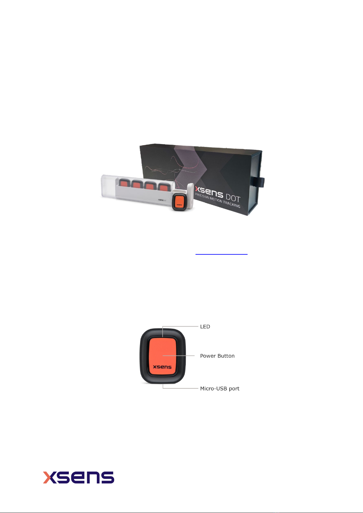
Figure 3: Xsens DOT sensor.................................................................................... 8
Figure 4: Charger with power cable ........................................................................10
Figure 5: Mag Norm is constant while moving ..........................................................12
Figure 6: Mag Norm fluctuates when moving ...........................................................13
Figure 7: Xsens DOT signal processing architecture ..................................................14
Figure 8: Xsens DOT state transition diagram ..........................................................15
Figure 9: USB power on disabled ............................................................................16
Figure 10: USB power on enabled...........................................................................16
Figure 11: Root and scanners in synchronization ......................................................17
Figure 12: Xsens DOT sensor coordinate system ......................................................22
Figure 13: Heading reset/revert in Xsens DOT app ...................................................23
Figure 14: Sensor technical drawing .......................................................................30
Figure 15: Charger technical drawing ......................................................................31

7
www.xsens.com
1Introduction
Xsens has released the 2nd generation of Xsens DOT hardware (hereinafter as v2). The
hardware upgrade includes specification improvements as well as user experience
optimizations. The Xsens DOT sensor and charger have been upgraded as a drop and
replaceable hardware to the existing first generation. Refer to the Product Change
Notification for the details about this upgrade. This document is applicable to v2 with the
latest firmware (v2.0.0) and software (v2021.0) versions. Refer to this link for the archived
user manual for v1 hardware.
Xsens DOT is a wearable sensor development platform which features sensor incorporating
3D accelerometer, gyroscope and magnetometer to provide an accurate 3D orientation.
The embedded processor in the sensor handles sampling, calibration, strap-down
integration of inertial data and the Xsens Kalman Filter core (XKFCore) algorithm for sensor
fusion. With wireless data transmission through Bluetooth 5.0, Xsens DOT can provide real-
time 3D orientation as well as calibrated 3D linear acceleration, angular velocity and (earth)
magnetic field data to a receiving device.
Xsens DOT is the start of a new Xsens product line bringing Xsens sensor solutions to
mobile device platforms. With simple-to-use Software-Development-Kit (SDK) and
comprehensive documentation, system integrators can easily develop their wearable
applications.
The Bluetooth Low Energy (BLE) data transmission, lightweight form factor and IP68 water-
proof rating widen the application areas of Xsens DOT, making it easy and durable to use
in various scenarios. Using different combinations of 5 sensors, it’s flexible to apply Xsens
DOT to customized measurement cases.
Fields of use:
1. Health and rehabilitation
2. Sports and exercise science
3. Ergonomics
Figure 1: Xsens DOT sensors with a charger

8
www.xsens.com
2Getting Started
2.1 Xsens DOT set
A standard Xsens DOT v2 set contains:
•5 Xsens DOT sensors
•1 charger with power cable
•Xsens DOT software package
Figure 2: Xsens DOT set
The easiest way to get started with Xsens DOT is to use the Xsens DOT App (Android/iOS)
to connect the sensors. You can get to know the capabilities of Xsens DOT and to configure
the sensor according to your needs. Refer to this unboxing tutorial to get started quickly.
2.2 Xsens DOT sensor
Xsens DOT sensor provides 3D angular velocity using a gyroscope, 3D acceleration using
an accelerometer and 3D earth magnetic field using a magnetometer. Combined with Xsens
sensor fusion algorithms, 3D orientation and free acceleration are provided. With the
wireless nature of Bluetooth 5.0, Xsens DOT sensor is an excellent measurement unit for
tracking human body motions.
Figure 3: Xsens DOT sensor
On top of the sensor is the LED giving the indications of sensor states. There is a power
button in the middle of the sensor. A micro-USB port at the bottom can be used to charge
the sensor.

9
www.xsens.com
2.2.1 Power on/off
The sensor can be powered on by pressing the power button for 2 seconds, and it can be
turned off by pressing the power button for over 3 seconds. During that, the LED will give
a clear indication by its LED patterns.
2.2.2 LED status
Xsens DOT v2 sensor has LED patterns to indicate different sensor states. Table 1 shows
the LED behavior and its meaning.
Table 1: LED patterns
State
LED
colour
LED patterns
Charging (battery ≤ 20%)
Fade in and out, 2-seconds cycle
Charging (20%< battery ≤90%)
Fade in and out, 2-seconds cycle
Fully charged (battery >90%)
ON
Power ON
ON for 2 seconds
Power OFF
ON for 1 second and then fade out
Power saving - OFF
Bluetooth broadcasting
Blink 1 time per second
Ready to use (Bluetooth
connected)
Blink 1 time every 10 seconds
Syncing
ON during sync period, all sensors blink
synchronously for 3 second if sync succeeds.
Measurement (both streaming and
recording)
Blink 2 times (very quick) every 2 seconds
Identify sensor
Blink 8 times (ultra-quick) and a short pause,
last for 10 seconds.
Bootloader - normal state
Blink 2 times (very quick) and a long pause
Bootloader - error state
ON
Microcontroller unit (MCU) or
battery overheated during
charging
Blink 8 times per second
2.2.3 Reset sensor
In case of firmware failure and the sensor cannot respond to any operations defined in the
firmware, a hardware reset function is necessary. Follow the steps below to reset the v2
sensor:
1. Press and hold the power button for a minimum of 11 seconds and then release
2. Power on the sensor again by pressing the power button for 2 seconds
2.3 Charger
The charger is a docking station for 5 sensors and includes a plastic cover shell, along with
a USB power cable. You can open the charger by holding the cover shell and pull out the
docking from the right side.

10
www.xsens.com
Each docking slot features an embedded micro-USB port. Sensors can be charged by
plugging them into the respective slots. Another micro-USB port placed on the right side
of the Xsens DOT charger is used to power on and charge all the sensors docked in the
charger. To power this micro-USB port, an adapter of 5V/300mA is enough but we would
recommend using a 5V/500mA adapter (5 sensor loads) based on standard USB 2.0 power
supply.
Figure 4: Charger with power cable
The USB communication hub is integrated in the v2 charger. Using the Xsens DOT Data
Exporter software installed on a PC, you can export the recording files from 5 sensors to
the PC at the same time via the charger.
2.4 Body straps and accessories1
Xsens provides the Xsens DOT Strap Set as an attachment method to secure Xsens DOT
on the body. You can place Xsens DOT sensors inside the pocket of strap and wrap the
strap around the segment of interest. This will ensure good adhesion and fewer skin
artefacts. Refer to this BASE article for more information on sensor attachment.
In addition to this, a set of adhesive patches is available as an alternative attachment
method. These are recommended for clinical applications.
2.5 Software
As Xsens DOT serves as a wearable sensor development platform, we provide all the
software needed for different demands. The software package can be download here and
includes:
•Xsens DOT Software Development Kit (Android/iOS)
•Xsens DOT App (Android/iOS)
•Xsens DOT Server
•Xsens DOT Data Exporter
•SDK Documentations (Android/iOS)
•SDK Programming guide for Android
•User Manual
•BLE Service Specifications
1Xsens DOT attachment solutions will be more diverse and flexible as we continue to improve

11
www.xsens.com
2.5.1 Supported platforms
Table 2: Software supported platforms
Software
Supported platforms
SDK and APK for Android
•Android OS 8.0 and above
•ARMv8 CPU architecture, arm64-v8a ABI (64-bit)
SDK and App for iOS •iOS 11.0 and above
Xsens DOT Server
•Windows 7, 10
•MacOS
•Raspberry Pi
Xsens DOT Data Exporter •Windows 10
Bluetooth requirements
•Best performance with BLE 5.0, DLE2supported
•Compatible with Bluetooth 4.2
2.5.2 Choose your software
You can choose to use different software according to your demands. Please refer to the
following instructions on how to choose your software:
•If you focus on the motion data and want to quickly understand the data outputs
and capabilities of Xsens DOT, download and install Xsens DOT App. It will allow
you to:
oScan and connect the sensors
oData real-time streaming
oRecord data in sensor and export to other devices
oMagnetic field mapping
oFirmware update and other functions
Refer to this BASE article for detailed guidance on Android App and iOS App
operations. Xsens DOT App tutorial video is also available.
•If you are a developer or system integrator wanting to build your own applications,
download Xsens DOT Software Development Kit (SDK) for Android or iOS
applications. Refer to the SDK programming guide and the following example code
to get started:
oAndroid example: https://github.com/xsens/xsens_dot_example_android
oAndroid example: https://github.com/xsens/xsens_dot_example_ios
•If you are familiar with Bluetooth protocol and development, and you want to build
applications on any other platforms with Bluetooth 5.0, a lower level Xsens DOT
BLE Service Specifications is provided to enable direct communication with Xsens
DOT. For Windows or MacOS, an open-source project - Xsens DOT Server is
provided. You can download it from: https://github.com/xsens/xsens_dot_server.
2Data Length Extension

12
www.xsens.com
2.6 Tips for best practice
2.6.1 Multiple sensors connection
Although there is no connection limit in the Xsens DOT app, SDK or BLE services; hardware
and OS constraints of the central devices have a ceiling to the maximum number of sensors
that can be connected simultaneously. For Android, MacOS and Windows, it is possible to
connect up to 7 sensors. In iOS, Linux PC or Raspberry Pi, it is possible to connect up to
11 sensors. The actual connection capability is highly dependent on the device you choose.
However, the BLE performance cannot be guaranteed if the connection limit is reached. If
big data loss or connection failure cases are observed, reduce the sensor connection
number or the transmission payload.
2.6.2 Magnetic distortion
Ferromagnetic material (iron or steel), magnets or strong electrical currents (several
amperes) in the environment near the sensor will cause disturbances to the local magnetic
field. The magnetometer in Xsens DOT sensors is used as a 3D compass to determine the
direction of the Earth true north (heading or yaw) and is used as an absolute reference in
the calculation of 3D orientation. For detailed information about the influence of magnetic
field on orientation, see the PhD thesis “Inertial and magnetic sensing of human movement
near ferromagnetic materials” D. Roetenberg 2006. For best results when measuring with
Xsens DOT, it is advised to avoid highly magnetized areas when carrying out
measurements, particularly in the beginning of the measurement.
To check the magnetic distortion, you can use the Xsens DOT App to check the Magnetic
Norm3in magnetic field data after connecting at least one DOT. Look at the Magnetic Norm
curve while moving in the measurement area.
•Areas for which the magnetic norm = 1 and the variation remains within ±0.2 are
magnetic homogeneous and is optimal for carrying out the measurements (see
Figure 5). However, if the measurement begins with a magnetic norm of around 2
or 3, and remains within ±0.2 of this value, the orientation should remain accurate.
•If the Mag Norm will vary depending on the location and orientation of the device
(see Figure 6), there are magnetic distortions in the environment.
Figure 5: Mag Norm is constant while moving
3Magnetic Norm (Mag Norm) is the norm of all magnetic axis vectors (X, Y and Z) combined. It can
be used as an indication of magnetic distortions.

13
www.xsens.com
Figure 6: Mag Norm fluctuates when moving
XKFCore algorithm running in the motion processor can compensate for the magnetic
disturbance caused by short or fast fluctuating disturbances by optimally using the
available sensor information and valid assumptions about the application. However, if the
disturbance is slow and large (>±0.2) or lasts for over 30s, it’s difficult for the algorithm
to compensate for and will influence heading accuracy.
If the magnetic field norm has large fluctuations, or the Xsens DOT sensor is attached to
an instrument or prosthesis that influences the magnetic field (e.g. ferromagnetic object),
it is best to carry out Magnetic Field Mapping for this DOT (see section 3.4) to recalibrate
the magnetometer.
NOTES:
•Never expose sensor to strong magnetic fields. The sensor contains the
absolute possible minimum of ferromagnetic materials. Nonetheless, some minor
components can be magnetized permanently by exposure to strong magnetic fields.
This will not damage the unit but will render the calibration of the magnetometers
useless, typically observed as a (large) deviation in the heading.
2.6.3 Cleaning method
To clean the Xsens DOT sensors and charger, use a moist cloth to wipe the surface.
2.6.4 Long-term storage guidelines
Follow the recommended guidelines to preserve the battery life of the sensors:
•Operating temperature: 0°C - 50°C.
•Storage temperature: 25°C±10°C.
If the sensors will be stored for a prolonged period of 3 months or longer:
1. Charge all sensors to >90%. You can know the battery level is >90% when the LED
shows solid green.
2. Disconnect sensors from charger.
3. Power off the sensors if they are powered on with the USB plugin.
Recharge your Xsens DOT sensors every 3 months according to the recommended
guidelines to slow the rate of battery ageing thereby improving the battery shelf life.

14
www.xsens.com
3Xsens DOT Overview
The signal processing architecture of Xsens DOT sensor is presented in Figure 7. The strap
down integration (SDI) and sensor fusion algorithms (XKFCore) are integrated into the
firmware. You can obtain the orientation increments and velocity increments from SDI, as
well as the 3D orientation and free acceleration from XKFCore. Xsens DOT sensor is factory
calibrated, making it more accurate repeatable and robust.
Figure 7: Xsens DOT signal processing architecture
3.1 Strapdown integration
Strap down integration is a method used to compute orientation and velocity increments
by integrating angular velocity from gyroscope and acceleration from the accelerometer.
The angular velocity and acceleration data are sampled and calibrated at a high frequency
(800 Hz) by the embedded MCU of Xsens DOT sensor to maintain accuracy under dynamic
movements such as running and jumping. Due to the high sampling frequency, the data
cannot be transmitted via Bluetooth directly and would typically present an excessive
computational load on the receiving host device (e.g., mobile phone). The SDI algorithm
receives the high-rate sensor input and processes it into a lower-rate signal at 60 Hz. The
main advantage of using the SDI algorithm is that the accuracy is maintained, and
information is preserved to ensure precise orientation tracking.
The SDK data parser has built-in functions to convert SDI quantities to calibrated angular
velocity (rad/s) and acceleration (m/s2) data. Refer to data conversion sections in SDK
programming guides.
3.2 Sensor fusion algorithm and filter profiles
The 3D orientation of the sensor is computed by Xsens’ latest Kalman filter core algorithm
(XKFCore) for sensor fusion, which is optimized for human motions. It uses the output
from SDI to compute a statistical optimal 3D orientation estimate of high accuracy, with
no drift for both static and dynamic movements. The XKFCore uses the measurement of
gravitational acceleration and Earth magnetic north to compensate for slowly increasing
errors from the integration of the rate of turn data, and also gives out free acceleration.

15
www.xsens.com
As described above, the XKFCore makes assumptions on the range of acceleration and
magnetic field sensed to obtain orientation. Since those quantities can widely differ among
different user applications, multiple filter profiles are introduced to improve the orientation
estimation accuracy. As a result, the XKFCore is optimised to suit different types of
movements and applications. Find below additional information on the filter profiles
available to choose which is best suited for your application.
Table 3: Filter profiles
Name Description
General
This filter profile is the default setting. It assumes moderate dynamics and a
homogeneous magnetic field. External magnetic distortion is considered
relatively short.
Dynamic
This filter profile assumes fast and jerky motions that last for a short time.
The dynamic filter uses the magnetometer for stabilization of the heading
and assumes very short magnetic distortions. Typical applications are when
sensors are applied on persons for sports such as sprinting.
3.3 Xsens DOT sensor state transition
Figure 8: Xsens DOT state transition diagram
3.3.1 Power ON
You can power on the sensor by pressing the power button for 2 seconds. Sensor will go
to advertisement mode after powered on.
With the firmware 2.0.0, there is more power on options to allow you to choose whether
to power on the sensor via USB plugin. By default, power on by USB is disabled. So, the
sensor will be in charging status if connected with USB cable. In the charging status, the
sensor keeps charging until battery full and it will not do Bluetooth advertising.

16
www.xsens.com
Figure 9: USB power on disabled
You can change this setting via Xsens DOT app (v2021.0) or the SDK (v2021.0). By
enabling USB power on, the sensor will power on immediately after the USB plugin. With
this feature, you can power on multiple sensors with the USB plugin at once.
Figure 10: USB power on enabled
3.3.2 Power OFF
Sensor will power off under 3 conditions:
1. Power button is pressed over 3 seconds
2. Receive power off command
3. Battery level is lower than 2%.
3.3.3 Advertisement
In advertisement mode, sensors will perform operation idle detection, waiting for BLE
connection from host devices. With the default power saving settings, if there is no BLE
connection detected over 10 minutes4during advertisement, the sensor will enter power
saving mode.
3.3.4 Connection
Once the Bluetooth connection is established, information such as MAC address, device tag
name, battery level and charging status... etc. can be retrieved from the sensor. In Xsens
DOT App, a reconnection will start automatically once the connection is lost.
If no measurement is started over 30 minutes5during connection, sensor will enter power
saving mode.
There is no sensor connection limit set in any software provided by Xsens. Refer to section
2.6.1 for best practices on connecting multiple sensors.
4Default time threshold which can be changed in Xsens DOT App, SDK or by BLE services.
5Default time threshold which can be changed in Xsens DOT App, SDK or by BLE services.

17
www.xsens.com
3.3.5 Synchronization
Each sensor has its own clock domain. So, it is important to have the measurement data
time-synchronized between different sensors, especially in scenarios where multiple
sensors are required simultaneously, e.g., calculation of joint angles.
All the sensors will be time-synced to a common sensor time base after synchronization.
As the sensor clock drifts, the synchronization accuracy will decrease over time (Table 4).
Table 4: Synchronization accuracy
Time Accuracy
After 30 min 1 ppm
After 1 hour 4 ppm
A successful synchronization will take about 14 seconds. During the synchronization, one
sensor will be the root node, whereas the remaining sensors are scanners. The root node
will periodically send out advertisement messages while the scanners will receive the
messages and correct their own time domain by calculating the skew and offset of the root
clock.
To achieve a better synchronization result, it is advised to put the root node in a central
position of all the scanners. In Xsens DOT app, the first connected sensor will be the root
node. SDK users and other developers can set their own rules to choose the root node.
Figure 11: Root and scanners in synchronization
Synchronization should take place before the measurement so that all the sensor data are
time-synced. After a synchronization, multiple measurements can be started and stopped
without additional synchronization. Refer to this BASE article for details about
synchronization in Xsens DOT app.
NOTES:
•Stop the synchronization after all the measurements to prolong the battery life.

18
www.xsens.com
3.3.6 Measurement
Two types of measurement are available with Xsens DOT. Table 5 shows the available
output rates for different types of measurement.
Table 5: Output rates
Measurement Available output rates
Real-time streaming 1Hz, 4Hz, 10Hz, 12Hz, 15Hz, 20Hz, 30Hz and 60Hz
Recording 1Hz, 4Hz, 10Hz, 12Hz, 15Hz, 20Hz, 30Hz, 60Hz and 120Hz
By choosing lower output rates, less data per unit time will be transmitted when compared
to the standard 60Hz output rate. As a result, this can mitigate the occurrence of data loss
in Real-Time Streaming mode and less data will be stored, thereby recording time can be
extended. Conversely, the higher output rate (120Hz) is better suited for high-dynamic
applications, where a larger amount of data is needed. However, the higher output rate is
only available for Recording mode.
Real-time streaming
In real-time streaming, motion data is streamed and logged to central device (such as the
mobile phone) via constant Bluetooth connection.
Sensor fusion data, inertial data and other custom data combinations are provided in real-
time streaming, together with packet counter and timestamp. Refer to Chapter 4 for data
output specifications.
NOTES:
•In the Xsens DOT App, to make plotting data readable, orientation data will always
be displayed in Euler angles, whereas data in the log file will be stored in the chosen
format (Euler or quaternion).
•In the Xsens DOT App, to make plotting data readable, inertial data will always be
displayed as acceleration (m/s2) and angular velocity (degrees/s) whereas data in
the log file will be stored in the chosen format (high fidelity, delta quantities or rate
quantities).
•Sensor will still be in streaming status even if the Bluetooth connection is lost. So
stop the streaming after every measurement to prevent battery drain.
High fidelity mode
High fidelity mode is available in real-time streaming. In this mode, Xsens proprietary data
format will be transmitted via Bluetooth and parsed in Xsens DOT App or SDK. The
advantage of this mode is that even in the case of transient data loss, higher frequency
(800 Hz) information is still preserved with lower output data rate (60 Hz).
High fidelity data will be parsed to delta_q, delta_v in Xsens DOT app. Functions to parse
high fidelity data to delta_q, delta_v or calibrated angular velocity and acceleration are
available in SDK. Refer to SDK programming guide for detailed information.

19
www.xsens.com
Recording
In recording mode, motion data is stored within the sensor internal storage and can be
exported for post-processing. The internal storage of the v2 DOT is 64MB. The available
recording time depends on the selected output frequency. For example, the available
recording time is around 6 hours at 60Hz. With higher output frequency comes less
available recording time.
Recording can be started and stopped using Xsens DOT App and these functionalities are
available in Xsens DOT SDK or BLE Service Specification manual. Bluetooth connection is
not required during recording.
Recording will also stop in the following situations:
•power button is pressed for 1 second during recording.
•time is up for timed recording sessions.
•flash memory is over 90%.
Data can be exported via Bluetooth or via USB connection. Wireless data transfer using
Bluetooth is suitable for exporting small files (a few minutes). However, when exporting
large amounts of data, it is recommended to use Xsens DOT Data Exporter to export via
USB on PC. Refer to this BASE article on how to use Data Exporter.
As a rule of thumb, when exporting from 5 sensors through the charger, the export speed
is around 0.16Mbps. It takes around 10 min to export 60 min’s recording at 60Hz.
When exporting data via Bluetooth, it is advised to select few sensors at a time to prevent
data transmission loss or connection failure. You can choose different types of data
configurations and select recording files when exporting.
Note that free acceleration is not included. For further information on how to calculate it
from other quantities, refer to this BASE article.
3.3.7 Power saving
In power-saving mode, sensors will turn off the signal pipeline and BLE connection, put the
MCU in a sleep state to ensure minimum power consumption. In this state, sensors cannot
be discovered by host devices.
The default time thresholds to enter power saving mode is set to 10 min in advertisement
mode and 30 min in connection mode. Power saving mode can be disabled and the time
thresholds can be adjusted in Xsens DOT App, SDK or by BLE services.
Sensors will exit power saving mode when:
•Power button is pressed
•Acceleration is detected by accelerometer
Once the sensor enters power saving mode, you can wake it up by pressing the power
button or simply shaking it. Xsens DOT will return to advertisement mode when exiting
power saving mode.

20
www.xsens.com
3.3.8 Button callback function
If there is a single click on the power button during connection, a BLE notification will be
sent with a timestamp when this single click is applied. This function is called “Button
callback”. It is further explained in the Xsens DOT SDK programming guide and the BLE
Service Specification. Refer to those for more information.
3.4 Magnetic Field Mapper
When Xsens DOT sensor is mounted to an object that contains ferromagnetic materials,
the measured magnetic field can become distorted, causing errors in measured orientation.
To correct for known magnetic disturbances, Magnetic Field Mapper function has been
developed to allow users to remap the magnetic field of the sensor.
The MFM can be executed in a few minutes and yields a new set of calibration values that
can be written to the Xsens DOT’s non-volatile memory, which means it will not be erased
by powering off or firmware updates.
You can perform MFM with 5 sensors at the same time. Follow these steps to do the MFM
for Xsens DOT. Here is a detailed BASE article about how to do MFM in the App.
1. Open Xsens DOT App (Android or iOS)
2. Connect the target sensors
3. Go to Advanced Magnetic Field Mapper
4. Select sensors to start MFM
5. Rotate the sensors slowly around all three axes and in all directions to collect data
for magnetic field calibration. The process automatically checks for data points that
are relevant and give sufficient coverage for a proper MFM procedure. The progress
bar indicates this and once the bar reaches 100%, MFM process will begin
automatically.
6. MFM is successful when showing “Finished”. Restart the MFM if it fails.
A .mtb file containing the calibration data will be created during the MFM. You can find it
in your mobile phone:
•Android: under this directory Android/data/com.xsens.dot.android/files/mfm
•iOS: Goto Files App On My iPhone Xsens DOT mfm
3.5 Firmware Update
Continuous firmware releases from Xsens are scheduled for new features, improvements,
and bug fixes. With Over-the-Air (OTA) firmware update function in Xsens DOT, you can
easily update the sensors to latest firmware version with Xsens DOT App.
For SDK users, device firmware update via OTA is published in v2021.0 SDK for both
Android and iOS. Refer to device firmware update sections in the SDK programming guide.
NOTES:
•Make sure App is updated to the latest version first before carrying out the OTA.
Other manuals for DOT
4
Table of contents
Other Xsens GPS manuals