Yaesu ADMS-8 User manual

ADMS-8
Operation Manual
The ADMS-8 software provides convenient editing of the FT2DR/DE memory channel
frequencies, channel information and alpha tags, using a personal computer. Also the
transceiver parameters and the setup menu items may be edited and congured easily
from the computer keyboard.
YAESU MUSEN CO., LTD.

2
TABLE OF CONTENTS
Introduction.....................................................4
System Requirements ...................................4
Operating system (OS) ..........................................4
CPU .......................................................................4
RAM (system memory) ..........................................4
HDD (Hard Disk) ....................................................4
Necessary PC peripheral interfaces ......................4
microSD .................................................................4
Cables....................................................................4
Display examples...........................................5
Before using the ADMS-8 FT2DR/DE
Programmer...................................................7
Using the ADMS-8 software ..........................7
Functions ........................................................8
File.................................................................8
New........................................................................8
Open ......................................................................8
Exit .........................................................................8
Save.......................................................................8
Save As..................................................................8
Import / Import with FT1DR/DE / FT2DR/DE
format.....................................................................9
Export / Export with FT1DR/DE / FT2DR/DE
format.....................................................................9
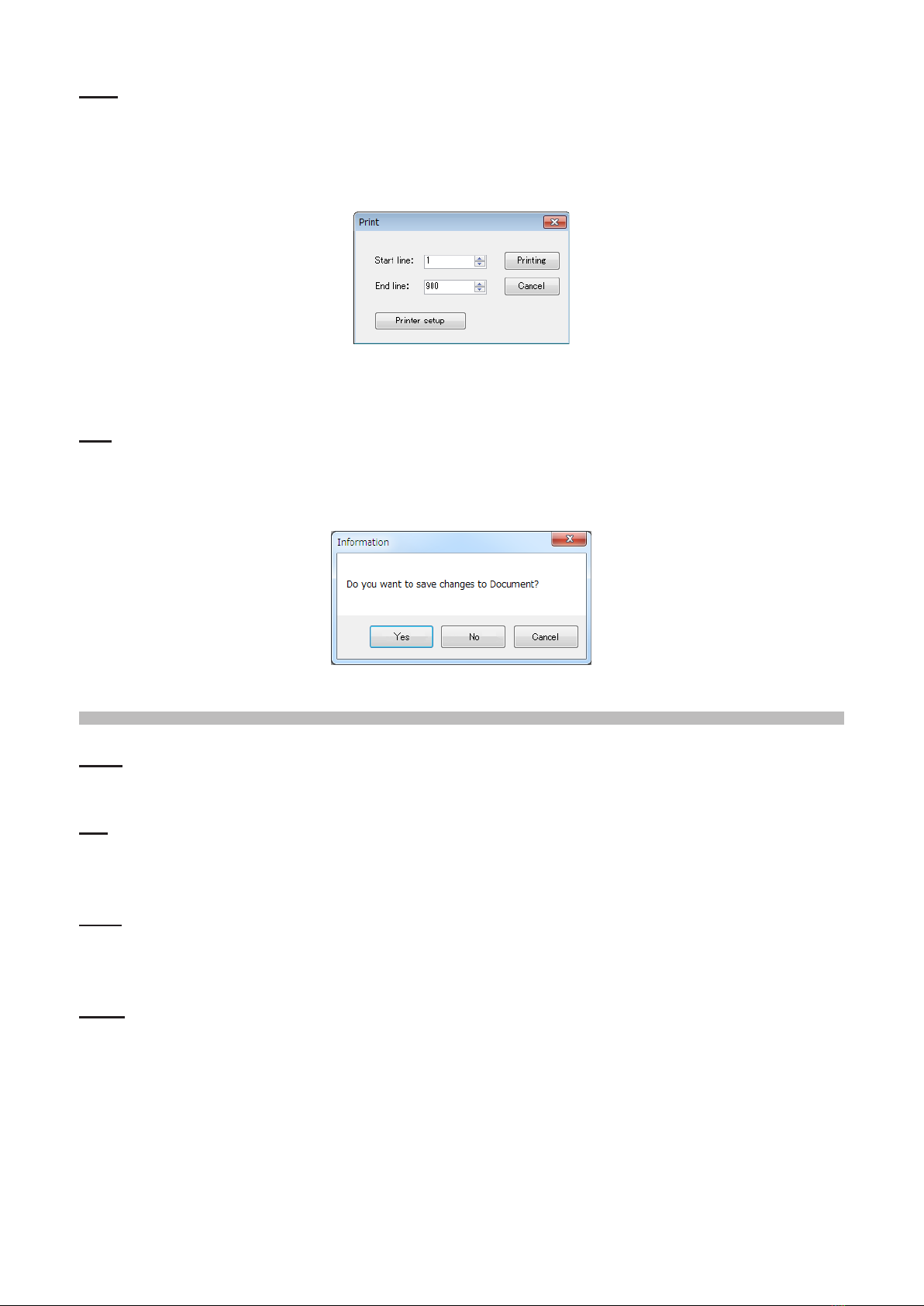
Print......................................................................10
End.......................................................................10
Edit...............................................................10
Undo ....................................................................10
Cut .......................................................................10
Copy.....................................................................10
Paste....................................................................10
Find ......................................................................11
Find Next..............................................................11
Goto Channel.......................................................11
Insert Channel......................................................11
Delete Channel ....................................................12
Clear Channel ......................................................12
Move Up...............................................................12
Move Down ..........................................................12
Add Frequency Range .........................................12
Sort ......................................................................13
Communications..........................................14
Get Data from FT2D ............................................14
Send Data to FT2D ..............................................15
Get Data From SD Card ......................................15
Send Data to SD Card .........................................16
COM port Settings ...............................................17
Settings........................................................17
Settings ................................................................17
Common ...........................................................17
GM_WIRES-X...................................................18
APRS GPS .......................................................19
APRS Beacon...................................................20
Memory.............................................................21
Tool Bar ...............................................................21
Status Bar ............................................................21
Window........................................................22
Tile(up and down) ................................................22
Tile(right and left) .................................................23
Cascade...............................................................23
Setting the Template Items..........................24
Memories ............................................................24
Priority CH ........................................................24
Receive Frequency / Transmit Frequency........24
Offset Frequency ..............................................24
Offset Direction .................................................24
Operating MODE ..............................................25
Name ................................................................25
Tone Mode........................................................25
CTCSS Frequency............................................25
DCS Code.........................................................25
DCS Polarity .....................................................25
User CTCSS .....................................................25
TX Power ..........................................................25
Skip...................................................................25
Step ..................................................................26
Memory Mask ...................................................26
ATT ...................................................................26
S-Meter SQL.....................................................26
Bell....................................................................26
Vibrator .............................................................26
Half DEV ...........................................................26
Clock Shift.........................................................26
BANK 1 to BANK 24 .........................................26
Comment ..........................................................26
SKIP.....................................................................27
PMS .....................................................................28
VFO A / VFO B ....................................................28
Receive Frequency...........................................29
Transmit Frequency..........................................29
Operating MODE ..............................................30
Tone Mode........................................................30
Comment ..........................................................30
HOME ..................................................................30
Receive Frequency / Transmit Frequency........31
Operating MODE ..............................................31
Comment ..........................................................31
SW Banks ............................................................32
BANK 1 to BANK 24 .........................................32
Comment ..........................................................32
Marine Banks .......................................................33
BANK 1 to BANK 24 .........................................33
Comment ..........................................................33

3
Weather ...............................................................34
BANK 1 to BANK 24 .........................................34
Comment ..........................................................34
Troubleshooting...........................................35
The FT2DR/DE cannot receive or transmit data
to the computer. ...................................................35
The Data transfer does not start. .........................35
The data transmission has stopped before
completion............................................................35
The data import/export is not successful. ............35
Contact YAESU Technical Support .............35

4
Introduction
The ADMS-8 programming software uses a Personal Computer to quickly enter and save the
FT2DR/DE memory channel frequencies and data. Also the many menu settings may be adapted
for individual operating preferences. All of the information is saved. The setting data can be imported
from the FT2DR/DE and edited setting data can be transferred to the FT2DR/DE. Furthermore, by
using the ADMS-8 software, memory channel information* can be exchanged between the FT1DR/
DE and FT2DR/DE.
* Some information such as memory tags are excluded.
System Requirements
In order to use this program, a personal computer (PC) with one of the following Windows operating
systems, and a serial data connection cable are required.
Operating system (OS)
Any one of the following operating system environments
Microsoft Windows®10 (32 bit/64 bit)
Microsoft Windows®8.1 (32 bit/64 bit)
Microsoft Windows®8 (32 bit/64 bit)
Microsoft Windows®7 (32 bit/64 bit, Service Pack 1 or later)
Microsoft Windows Vista®(32 bit/64 bit, Service Pack 2 or later)
CPU
The performance of the CPU must be able to satisfy the operating system requirements.
RAM (system memory)
The capacity of the RAM (system memory) must be more than sufficient to satisfy the operating
system requirements.
HDD (Hard Disk)
The capacity of the HDD must be more than sufcient to satisfy the operating system requirements.
In addition to the memory space required to run the operating system, about 50 MB or more of
additional memory space is required to run the program.
Necessary PC peripheral interfaces
USB port (USB 1.1 / USB 2.0) or RS-232C interface (COM port)
microSD
Commercially available microSD memory card
* When using the following cables, a microSD memory card is not necessary.
Cables
• When using a USB port on the computer: the optional SCU-19 PC connection cable for USB
• When using a COM port connection: the optional SCU-16 and CT-169 cables
* When using the SCU-19 or SCU-16 cable, be sure to install the designated driver before
connecting the cable to the computer.
* When using a microSD memory card, these cables are not necessary.

5
Display examples
This is the rst screen to be displayed when starting the ADMS-8 software.
Click the left mouse button on the icon of the Title bar to enlarge a window.
The display window is shown in Full screen mode.

6
Click the left mouse button on each TAB in the title bar (PMS, VFOA, etc) to display the frequency list
of the desired memory channels, VFO and other preset transceiver settings.
Basic setting items which are not related to memory channels can be congured from “SetMode”.
Click the left mouse button on each item of the "Settings" in the "Settings" menu to open the item
"SetMode" window.

7
Before using the ADMS-8 FT2DR/DE Programmer
When using the optional SCU-19 PC USB connection cable, or the SCU-16 USB serial adaptation
cable, be sure to install the designated driver before connecting either cable to the computer.
Select the communication port that is connected to the FT2DR/DE.
Click the left mouse button on the "COM port Settings" item in the "Communications" menu to open
the "COM Port Settings" window.
Click the left mouse button on the "▼" button to display the COM Port List, and then click the left
mouse button on the communication port that is connected to the FT2DR/DE.
When using the SCU-19 or SCU-16, open the Device Manager on the computer and then click the
port (COM or LPT) to select the port number (COM**) displayed as Prolic USB-to-Serial Comm Port
(COM**).
If Prolic USB-to-Serial Comm Port is not displayed in the COM port list, the driver for SCU-19 or
SCU-16 is not installed correctly. Install the device driver correctly to the computer.
After correctly installing the SCU-19 or SCU-16 drivers, if the COM Port number is not correct and the
popup message “The port COMxx does not exist” is displayed click OK. Open [Device Manager] and
nd the correct COM Port number. Then choose the correct COM Port number from the list, or type
the correct COM Port number. Then click the [Determine] button to save the setting.
Using the ADMS-8 software
To enable the FT2DR/DE clone mode for use with the ADMS-8 software, use the following procedure:
1. Turn FT2DR/DE power OFF.
2. While pressing the key turn the power ON.
3. To acquire data from the FT2DR/DE, touch “RECEIVE”. To transfer data to the FT2DR/DE, touch
“SEND”.

8
Functions
File
New
Creates a new conguration le.
Click the left mouse button on the “New” parameter in the “File” menu to open a new conguration
le.
Multiple conguration les may be created and opened at the same time.
Standard values are preset for each memory channel, VFO and set mode.
Open
Opens a previously saved conguration le.
Click the left mouse button on the "Open" parameter in the "File" menu to display the “Open” window.
Select the existing saved template le, and click the “Open” button.
Exit
Close the displayed template le by clicking the left mouse button on the “Close” parameter in the “File”
menu.
If the present conguration has not been saved, you will be asked to conrm whether or not you wish
to save it.
Save
To save the present conguration, and overwrite the selected conguration le without changing the
le name, click the left mouse button on the "Save" parameter in the "File" menu.
Save As
To save the configuration file with a new name, click the left mouse button on the "Save As"
parameter in the "File" menu. Specify the file name and destination folder for the selected
conguration le and then click the “Save” button to save the le.

9
Import / Import with FT1DR/DE / FT2DR/DE format
ADMS-8 data les may be created using a spreadsheet such as Microsoft Excel.
To create a data le for the import of data, save the spreadsheet in the "CSV" comma separated le
format.
A spreadsheet may be easily created by exporting the template data in the "CSV" format using the
ADMS-8 "Export" command. After the "CSV" data has been edited the spreadsheet may be imported
back into the ADMS-8 Programmer. (See the "Export" command instructions below for details).
A separate import le is needed for each template.
For example, to import the VFO and memory templates; rst, click the "VFO" tab to display the VFO
template, then import the VFO (CSV) file; next, click the "Memories" tab to display the "Memory"
template; then import the Memory (CSV) le.
Do not edit the "Check" line at the right side end of the completed CSV le.
Export / Export with FT1DR/DE / FT2DR/DE format
To export the data le in the “CSV” (Comma Separated Values) format, click the left mouse button on
the "Export" parameter in the "File" menu, On the “Save as” screen displayed, specify the directory
and le name and save the le.

10
Print
To print the current template file data to hard copy, click the left mouse button on the "Print"
parameter in the "File" menu, the "Print" window will open to enable printing. Set the start line and the
end line of the data you want to print, and then click the left mouse button on the "Printing" button to
start printing.
To change the specic printer settings, go to the Printer properties by clicking the left mouse button
on the "Printer setup" button.
End
To exit the ADMS-8 programmer, click the left mouse button on the "End" parameter in the "File"
menu to close the ADMS-8 software. If the following pop-up screen appears to conrm saving, follow
the on-screen instruction to select the desired button and close the ADMS-8 software.
Edit
Undo
To undo the edited data, click the left mouse button on the "Undo" parameter in the "Edit" menu.
Cut
To cut the data of the selected area, click the left mouse button on the "Cut" parameter in the "Edit"
menu.
Copy
To copy the data of the selected area to the clipboard, click the left mouse button on the "Copy"
parameter in the "Edit" menu.
Paste
To paste the clipboard data to the selected area, click the left mouse button on the "Paste" parameter
in the "Edit" menu.

11
Find
To nd a specied text, click the left mouse button on the "Find" parameter in the "Edit" menu. The
"Find" window will open.
Select the column from the dropdown list. Enter the text to search for, and then click the left mouse
button on the [OK] button. The candidate character string found will be highlighted.
Find Next
Click the left mouse button on the "Find Next" parameter in the "Edit" menu to move to the next
candidate character string
Goto Channel
Move the cursor to the desired channel, click the left mouse button on the "Goto Channel" parameter
in the "Edit" menu to open the screen where you can specify the channel you want to move to.
Enter the channel number you wish to nd, and then click the left mouse button on the [OK] button.
Insert Channel
To insert channel data, click the left mouse button on the "Insert Channel" parameter in the "Edit"
menu to create a blank new channel data row under a current cursor. If there are any higher channel
numbers with channel data, the higher channel numbers will be displayed after the newly inserted
channel number so that the channels are displayed in the ascending order.
Attempting to insert a new channel when channel No. 900 contains data causes the data registered
to channel No. 900 to be deleted. The conrmation message will appear. If you accept the deletion,
click the [OK] button. The channel insert operation will be performed and the data registered to
channel No. 900 will be deleted.

12
Delete Channel
To delete the specied range of channel data, click the left mouse button on the “Delete Channel”
parameter in the “Edit” menu. The channels that were displayed after the deleted channels will shift
up accordingly.
Clear Channel
To clear the current channel data, click the left mouse button on the "Clear Channel" parameter in
the "Edit" menu. The channels that were displayed after the deleted channels will not shift up and the
blank channels will remain.
Move Up
To move the current channel data up one row, click the left mouse button on the "Move Up"
parameter in the "Edit" menu. If other channel data already exists where the channel data moves, the
existing channel will be overwritten.
Move Down
To move the current channel data down one row, click the left mouse button on the "Move Down"
parameter in the "Edit" menu, the currently selected channel data moves downward one row. If other
channel data already exists where the channel data moves, the existing channel will be overwritten.
Add Frequency Range
New channels may be created in designated frequency steps from the starting frequency by clicking
the left mouse button on the "Add Frequency Range" parameter in the "Edit" menu. The "Add
Frequency Range" window will open. A specified number of memory channels may be created,
beginning from the starting frequency in the specied frequency steps.
• Starting Frequency
Enter the lower frequency
• Number of Channel
Enter the number of channels
• Frequency Step
Enter the desire frequency step
Click the left mouse button on the [OK] button to create the additional specied memory channels.
* The 8.33 kHz step is available only when receiving on the Air band (108-136.99166 MHz).

13
Sort
Click the left mouse button on the "Sort" parameter in the "Edit" menu, the "Sort" window will open.
• Sort by:
Select the rst parameter for sorting items such as the order of frequencies.
• Then sort by:
Select the second parameter for sorting.
• Sort Mode:
Set to sort in ascending or descending order.
• Channels Sort Selection:
Set whether to sort the selected channel column(s) or to sort all channel columns.
Click the left mouse button on the [OK] button to initiate the sorting according to the above
instructions.
The data may be restored to the previous order by using the "Undo" command.

14
Communications
Get Data from FT2D
This command transfers the settings data of the FT2DR/DE to the ADMS-8 programmer. To
communicate with the FT2DR/DE and create a new data le, click the left mouse button on the "Get
Data from FT2D" parameter in the "Communications" menu. The "Get Data From FT2D" window will
open.
Connect the supplied SCU-19 or SCU-16 programming cable between the FT2DR/DE and the
Personal Computer.
Follow the on-screen instructions to acquire data from the FT2DR/DE. When the data transfer is
completed, the template screen received from the FT2DR/DE appears on the computer display. The
memory channels and conguration menu data may be edited using the ADMS-8 software tools.
This template and conguration data may be saved to the computer hard drive, using the "Save" or
"Save as" commands in the "File" menu.

15
Send Data to FT2D
This command downloads the ADMS-8 data from the computer to the FT2DR/DE.
Click the left mouse button on the "Save Data to FT2DR/DE" parameter in the "Communications"
menu. The transmission procedure screen will open.
To load a previously created data file to the FT2DR/DE, click the “Open” parameter in the “File”
menu, and open the desired le before performing the send data operation above.
Connect the supplied SCU-19 or SCU-16 programming cable between the FT2DR/DE and the
Personnel Computer.
Follow the on-screen instructions to transmit data to the FT2DR/DE. After the data transmission
completes, the FT2DR/DE will automatically start up in accordance with the set data.
* Never disconnect SCU-19 or SCU-16 programming cable while data transmission is in progress.
* Pay careful attention to the power cable and the connections to the FT2DR/DE and the computer,
so as not to lose the power during data reception/transmission.
Get Data From SD Card
This command imports the settings data from the microSD memory card to the ADMS-8 programmer,
and creates a new data le.
Click the left mouse button on the "Get Data from SD card" parameter in the "Communications"
menu, the data import procedure screen will open.
Insert the microSD memory card with the saved data from FT2DR/DE to the computer.
Select the data to import from the microSD memory card.
Follow the on-screen instructions to select the desired le and then click “Open” to import the data
le.
When the data transfer is complete, the template screen which was imported from the FT2DR/DE via
the microSD memory card will appear on the computer screen.
This data may be edited using the computer.

16
The template data may be stored to the computer les, using the "Save" or "Save as" commands in
the "File" menu.
Send Data to SD Card
Memories and settings from the ADMS-8 programmer may be transferred to the microSD memory
card.
Click on "Send Data to SD card" in the "Communications" menu to open the data transmission
procedure screen.
To transmit previously created data to the microSD memory card, click “Open” in the “File” menu and
open the desired le before performing the Send Data to SD card operation above.
Make sure that the microSD memory card to which you want to save the setting data is inserted into
the computer SD card slot.
Follow the instructions on the screen to copy the data to the SD card. When the data letransfer to
the SD card is complete, a notice "Complete" is displayed on the computer screen.

17
COM port Settings
Select the COM port that is connected to the FT2DR/DE.
For details about “COM port Setting”, see "Before using the ADMS-8 FT2DR/DE Programmer" (Page
7).
Settings
Settings
From the set mode menu, you can customize the various functions of the FT2DR/DE according
to your preferences. The ADMS-8 software displays the set mode menu in an easy-to-understand
manner where you can change and save the setting values.
Click the left mouse button on the "Settings" parameter in the "Settings" menu to open the "SetMode"
window.
The “SetMode” window template consists of ve setting screens: “Common”, “GM_WIRES-X”, “APRS
GPS”, “APRS Beacon”, and “Memory”. The screens may be switched by clicking the corresponding
le tab.
Common
On the “Common” screen, you can congure basic settings for the FT2DR/DE.

18
To change the setting of each item in the window, click the left mouse button on the "▼" icon to show
the dropdown settings list, and then click the desired selection in the list.
Example:
Enter the "DTMF SELECT" Codes by placing the curser in the appropriate box and typing the desired
data.
Refer to the "FT2DR/DE Operating Manual" for the details of each function.
GM_WIRES-X
The settings related to the GM and WIRES-X functions of the FT2DR/DE may be congured with the
programming software.
To change the setting of each item in the window, click the left mouse button on the "▼" icon to show
the dropdown settings list, and then click the desired selection from the list. Enter the "CATEGORY",
"GROUP", and "MESSAGE SAVE" information by placing the curser in the appropriate box and
typing the desired data.
Refer to the "FT2DR/DE Operating Manual" for the details of each function.

19
APRS GPS
The settings related to the APRS and GPS functions of the FT2DR/DE may be congured with the
programming software.
To change the setting of each item in the window, click the left mouse button on the "▼" icon
to show the dropdown settings list, and then click the desired selection from the list. Enter the
"Callsign(APRS)", "APRS MSG Text", "APRS MSG Group", and "My Position" information by placing
the curser in the appropriate box and typing the desired data.
Refer to the "FT2DR/DE Operating Manual" for the details of each function.

20
APRS Beacon
The settings related to the APRS and beacon functions of the FT2DR/DE may be congured with the
programming software.
To change the setting of each item in the window, click the left mouse button on the "▼" icon to show
the dropdown settings list, and then click the desired selection from the list. Enter the "Beacon Status
Text" and "Digi Path" by placing the curser in the appropriate box and typing the desired data.
Refer to the "FT2DR/DE Operating Manual" for the details of each function.
Table of contents