Yamaha CRX-M170 User manual

100975
SERVICE MANUAL
CRX-M170
IMPORTANT NOTICE
This manual has been provided for the use of authorized YAMAHA Retailers and their service personnel.
It has been assumed that basic service procedures inherant to the industry, and more specifically YAMAHA Products, are already
known and understood by the users, and have therefore not been restated.
WARNING: Failure to follow appropriate service and safety procedures when servicing this product may result in personal
injury, destruction of expensive components and failure of the product to perform as specified. For these reasons,
we advise all YAMAHA product owners that all service required should be performed by an authorized
YAMAHA Retailer or the appointed service representative.
IMPORTANT: The presentation or sale of this manual to any individual or firm does not constitute authorization, certification or
recognition of any applicable technical capabilities, or establish a principle-agent relationship of any form.
The data provided is believed to be accurate and applicable to the unit(s) indicated on the cover. The research, engineering, and
service departments of YAMAHA are continually striving to improve YAMAHA products. Modifications are, therefore, inevitable
and specifications are subject to change without notice or obligation to retrofit. Should any discrepancy appear to exist, please contact
the distributor's Service Division.
WARNING: Static discharges can destroy expensive components. Discharge any static electricity your body may have accumu-
lated by grounding yourself to the ground buss in the unit (heavy gauge black wires connect to this buss).
IMPORTANT: Turn the unit OFF during disassembly and parts replacement. Recheck all work before you apply power to the unit.
MAINTENANCE FLOW CHART (TUNER) ..................9
WIRING DIAGRAM .....................................................10
PRINTED CIRCUIT BOARD ................................11–13
BLOCK DIAGRAM......................................................14
SCHEMATIC DIAGRAM.......................................15–17
REMOTE CONTROL ..................................................19
PARTS LIST..........................................................20–21
■ CONTENTS
TO SERVICE PERSONNEL.....................................2–3
PREVENTION OF ELECTRO STATIC DISCHARGE
.....4
REAR PANEL ...............................................................4
SPECIFICATIONS.........................................................5
INTERNAL VIEW ..........................................................6
DISASSEMBLY PROCEDURES ..............................6–8
MAINTENANCE FLOW CHART (CD) .........................9
CD/DAB RECEIVER
CRX-M170
STANDBY/ON
1 2 3 4
5 6 7 8
9 0
BAND PRESET TUNER
TIMER DIMMER
SLEEP
FUNCTION/
FM MODE
INFO/TEXT AUTOTUNE
ENTER
AUX 2AUX 1 TAPE CD
REPEAT A-B PROG CLEAR
RANDOM TIME
MUTE
VOLUME
+
–
© 2005 YAMAHA CORPORATION. All rights reseved.
This manual is copyrighted by YAMAHA and may not be copied or
redistributed either in print or electronically without permission.
’05.09

CRX-M170
2
CRX-M170
■ TO SERVICE PERSONNEL
WARNING: CHEMICAL CONTENT NOTICE!
The solder used in the production of this product contains LEAD. In addition, other electrical/electronic and/or
plastic (where applicable) components may also contain traces of chemicals found by the California Health and
Welfare Agency (and possibly other entities) to cause cancer and/or birth defects or other reproductive harm.
DO NOT PLACE SOLDER, ELECTRICAL/ELECTRONIC OR PLASTIC COMPONENTS IN YOUR MOUTH FOR
ANY REASON WHATSOEVER!
Avoid prolonged, unprotected contact between solder and your skin! When soldering, do not inhale solder fumes
or expose eyes to solder/flux vapor!
If you come in contact with solder or components located inside the enclosure of this product, wash your hands
before handling food.
WARNING: Laser Safety
This product contains a laser beam component. This component may emit invisible, as well as visible radiation,
which may cause eye damage. To protect your eyes and skin from laser radiation, the following precautions must
be used during servicing of the unit.
1) When testing and/or repairing any component within the product, keep your eyes and skin more than 30 cm away from
the laser pick-up unit at all times. Do not stare at the laser beam at any time.
2) Do not attempt to readjust, disassemble or repair the laser pick-up, unless noted elsewhere in this manual.
3) CAUTION : Use of controls, adjustments or performance of procedures other than those specified herein may result in
hazardous radiation exposure.
About Lead Free Solder
The P.C.B.s installed in this unit are soldered using the following solder.
SIDEA SIDEB
MAINP.C.B. LeadFreeSolder LeadFreeSolder
POWERP.C.B. − LeadFreeSolder
Side A
Side B
SMT REFLOW Process
MI FLOW Process
Solder Dip
Among some types of lead free solder currently available, it is recommended to use one of the following types for the repair
work.
• Sn + Ag + Cu (tin + silver + copper)
• Sn + Cu (tin + copper)
• Sn + Zn + Bi (tin + zinc + bismuth)
Caution:
1. As the melting point temperature of the lead free solder is about 30°C to 40°C (50°F to 70°F) higher than that of the lead
solder, be sure to use a soldering iron suitable to each solder.
2. If lead solder must be used, be sure to remove lead free solder from each terminal section of the parts to be replaced and from
the area around it completely before soldering, or make sure that the lead free solder and lead solder melt together fully.

CRX-M170
CRX-M170
3
Laser Emitting conditions:
1) When the Top Cover is removed, and the “STANDBY/ON” SW is turned to the "ON" position, the laser component will
emit a beam for several seconds to detect if a disc is present. During this time (5-10 sec.) the laser may radiate through
the lens of the laser pick-up unit. Do not attempt any servicing during this period!
If no disc is detected, the laser will stop emitting the beam. When a disc is set, you will not be exposed to any laser
emissions.
2) The laser power level can be adjusted with the VR on the pick-up PWB. However, this level has been set by the factory
prior to shipping from the factory. Do not adjust this laser level control unless instruction is provided elsewhere in this
manual. Adjustment of this control can increase the laser emission level from the device.
Laser Diode Properties
●Material : GaAlAs
●Wavelength : 789 nm
●Emission Duration : Continuous
●Laser Output : max. 44.6 µW*
* This output is the value measured at a distance of about
200 mm from the objective lens surface on the Optical
Pick-up Block.
When checking the laser diode emission, keep your eyes more
than 30 cm away from the objective lens.
VARO! : AVATTAESSA JA SUOJALUKITUS OHITETTAESSA OLET ALTTIINA NÄKYMÄTTÖMÄLLE
LASER-SÄTEILYLLE. ÄLÄ KATSO SÄTEESEEN.
VARNING! : OSYNLIG LASERSTRÅLNING NÄR DENNA DEL ÄR ÖPPNAD OCH SPÄRREN ÄR URKOPPLAD.
BETRAKTA EJ STRÅLEN.
Optical Pick-up
ADVARSEL - USYNLIG LASERSTR≈LING VED ≈BNING, N≈R
SIKKERHEDSAFBRYDERE ER UDE AF FUNKTION.
UNDG≈UDS∆TTELSE FOR STR≈KING.
VAROITUS! - SUOJAKOTEL OA EI SAA AVATA. LAITE SISƒLTƒƒ
LASERDIODIN, JOKA LƒHETTƒƒ (NƒKYMƒT÷NTƒ)
SILMILLE VAARALLISTA LASERSƒTEILYƒ.
ADVARSEL - USYNLING LASERBESTR≈LING N≈R DENNE DELEN ER
≈PEN OG SIKKERHETSSPERREN ER UTKOBLET.
UNNG≈UTSETTELSE FOR STR≈LING.
CAUTION - INVISIBLE LASER RADIATION WHEN OPEN AND
INTERLOCKS DEFEATED, AVOID EXPOSURE TO
BEAM.
VORSICHT! UNSICHTBARE LASERSTRAHLUNG TRITT AUS, WENN
DECKEL GE÷FFNET UND WENN SICHERHEITSVER-
RIEGELUNG ‹BERBR‹CKT IST . NICHT DEM STRAHL
AUSSETZEN!.
VARNING - OSYNLING LASERSTR≈LNING NƒR DENNA DEL ƒR
÷PPNAD OCH SPƒRR ƒR URK OPPLAD. STR≈LEN ƒR
FARLIG.
MODEL NO. RDX-E700
CLASS 1 LASER PRODUCT
LASER KLASSE 1 PRODUKT
LUOKAN 1 LASERLAITE
KLASS 1 LASER APPARAT
PRODUIT LASER DE CLASSE 1

CRX-M170
4
CRX-M170
■PREVENTION OF ELECTRO STATIC DISCHARGE
Some semiconductor (solid state) devices can be damaged easily by static electricity. Such components commonly are called Electrostatically
Sensitive (ES) Devices. Examples of typical ES devices are integrated circuits and some field-effect transistors and semiconductor “chip”
components. The following techniques should be used to help reduce the incidence of component damage caused by electro static discharge
(ESD).
1. Immediately before handling any semiconductor component or semiconductor-equipped assembly, drain off any ESD on your body by touching
a known earth ground. Alternatively, obtain and wear a commercially available discharging ESD wrist strap, which should be removed for
potential shock reasons prior to applying power to the unit under test.
2. After removingan electrical assemblyequipped with ESdevices, place the assemblyon a conductivesurface such asaluminum foil, toprevent
electrostatic charge buildup or exposure of the assembly.
3. Use only a grounded-tip soldering iron to solder or unsolder ES devices.
4. Use only an anti-static solder removal device. Some solder removal devices not classified as “anti-static (ESD protected)”can generate
electrical charge sufficient to damage ES devices.
5. Do not use freon-propelled chemicals. These can generate electrical charges sufficient to damage ES devices.
6. Do not remove a replacement ES device from its protective package until immediately before you are ready to install it. (Most replacement ES
devices are packaged with leads electrically shorted together by conductive foam, aluminum foil or comparable conductive material).
7. Immediately before removing the protective material from the leads of a replacement ES divice, touch the protective material to the chassis or
circuit assembly into which the device will be installed.
CAUTION: Be sure no power is applied to the chassis or circuit, and observe all other safety precautions.
8. Minimize bodily motions when handling unpackaged replacement ES devices. (Otherwise harmless motion such as the brushing together of
your clothes fabric or the lifting of your foot from a carpeted floor can generate static electricity (ESD) sufficient to damage an ES device).
Grounding for electrostatic breakdown prevention
1. Human body grounding.
Use the antistatic wrist strap to discharge the static
electricity from your body.
2. Work table grounding.
Put a conductive material (sheet) or steel sheet on the area
where the optical pickup is placed and ground the sheet.
Caution:
The static electricity of your clothes will not be grounded
through the wrist strap. So take care not to let your clothes
touch the optical pickup.
1M-ohms
Conductive material
(sheet) or steel sheet
Anti-static wrist strip
■REAR PANEL

CRX-M170
CRX-M170
5
■ FM SECTION
Tuning Range (50 kHz steps) . . . . . . . . . 87.50 to 108.00 MHz
Signal to Noise Ratio (Mono) . . . . . . . . . . . . . . . . . . . . . .65 dB
Sensitivity (S/N 30 dB) . . . . . . . . . . . . . . . . . . . . . . . . 1.0 µV/m
■ AUDIO SECTION
Minimum RMS Output Power Per Channel
1 kHz, 0.1% THD, 6 ohms . . . . . . . . . . . . . . . . . . .25 W + 25 W
Input Sensitivity/Impedance
Tape, AUX 1, AUX 2 . . . . . . . . . . . . . . . . 300 mV/47 k-ohms
Output Level
REC OUT . . . . . . . . . . . . . . . . . . . . . . . . . . . . . . . . . 280 mV
SUB WOOFER (50Hz) . . . . . . . . . . . . . . . . . . . . . . . . . 2.0 V
Headphone Jack Rated Output
CD, etc. (32 ohms) . . . . . . . . . . . . . . . . . . . . . . . . . . . . 1.0 V
Frequency Response
CD, etc (20Hz to 20kHz) . . . . . . . . . . . . . . . . . . . . . . ±0.5 dB
Total Harmonic Distortion
CD, etc. 1 kHz . . . . . . . . . . . . . . . . . . . . . . . . . . . . . . . 0.03%
Signal to Noise Ratio (IHF-A-Network)
CD, etc. (300 mV, Input Shorted) . . . . . . . . . . . . . . . . .98 dB
Tone Control Characteristics
BASS Boost/cut . . . . . . . . . . . . . . . . . . ±10 dB (100 Hz)
TREBLE Boost/cut . . . . . . . . . . . . . . . . . . ±10 dB (10 kHz)
■SPECIFICATIONS
■ AM SECTION
Tuning Range (9 kHz steps) . . . . . . . . . . . . . . .531 to 1629kHz
Signal to Noise Ratio . . . . . . . . . . . . . . . . . . . . . . . . . . . .35 dB
Sensitivity . . . . . . . . . . . . . . . . . . . . . . . . . . . . . . . . . .600 µV/m
■GENERAL
Power Supply . . . . . . . . . . . . . . . . . . . . . . . . . AC 230V, 50 Hz
Power Consumption . . . . . . . . . . . . . . . . . . . . . . . . . . . . . 75 W
Standby Power Consumption . . . . . . . . . . . . . . . . . . . . .0.9 W
Dimensions (W x H x D) . . . . . . . . . . . . . .215 x 110 x 359 mm
(8-7/16" x 4-5/16" x 14-1/8")
Weight . . . . . . . . . . . . . . . . . . . . . . . . . . . . 4.4 kg (9 lbs. 11 oz)
Finish . . . . . . . . . . . . . . . . . . . . . . . . . . . . . . . . . . . . Silver color
Accessories . . . . . . . . . . . . . . . . . . . . . . AM loop antenna x 1
Indoor FM antenna x 1
Indoor DAB antenna x 1
Remote Control x 1
Battery (size "AAA", "R03", "UM-4") x 2
* Specifications subject to change without notice.
B ....... British model
■ DAB SECTION
Tuning Range (BAND
III
) . . . . . . . . . . . . 174 MHz to 240 MHz
Input . . . . . . . . . . . . . . . . . . . . . . . . . . . . . . . 50 ohms (nominal)
Sensitivity . . . . . . . . . . . . . . . . . . . . . . . . . . . . . . . . . .–96 dBm
Selectivity . . . . . . . . . . . . . . . . . . . . . . . . . . . . . . . . . 35 dB typ.
Audio Out . . . . . . . . . . . . . . . . . . . . . . . . . . . . Stereo, 2.0 Vp-p
Digital Out . . . . . . . . . . . . . . . . . . . . . . 24 bit/48 kHz resolution
■ CD PLAYER SECTION
Signal to Noise Ratio . . . . . . . . . . . . . . . . . . . . . . . . . . . .90 dB
Total Harmonic Distortion . . . . . . . . . . . . . . . . . . . . . . 0.007%
Separation . . . . . . . . . . . . . . . . . . . . . . . . . . . . . . . . . . . .90 dB
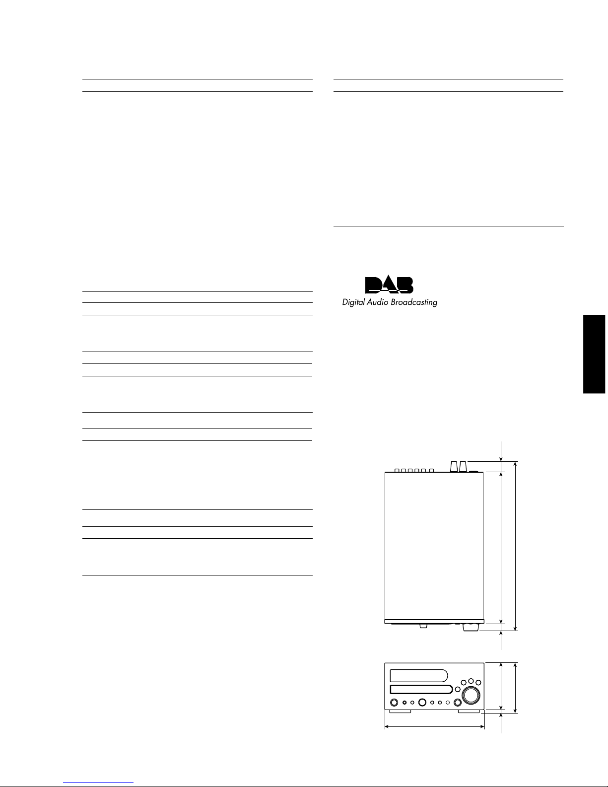
● DIMENSIONS
Unit : mm (inch)
215 (8-7/16")
110 (4-5/16")
101 (4") 320 (12-5/8")9
(3/8") 17
(11/16") 22
(7/8")
359 (14-1/8")
DAB (Digital Audio Broadcasting), also known as digital
radio, is a new way of radio broadcasting. DAB is
broadcast using digital signals instead of analog signals,
resulting in near CD-quality sound. Analog signals (i.e.
AM/FM) are susceptible to interference (i.e. distortion and
noise) caused by electrical equipment, weather conditions,
tall buildings, mountains, etc.; digital signals are not.
Thus, with DAB, there is virtually interference-free
reception and no hiss or crackle.

CRX-M170
6
CRX-M170
qMAIN P.C.B.
wPOWER (6) P.C.B.
ePOWER (1) P.C.B.
rPOWER (4) P.C.B.
tPOWER (5) P.C.B.
yCD MECHANISM UNIT
uPOWER (2) P.C.B.
iPOWER (3) P.C.B.
■INTERNAL VIEW
wer tq
uiy
■DISASSEMBLY PROCEDURES
1. Removal of Top Cover
a. Remove 2 screws ( q ) and 4 screws ( w ). (Fig. 1)
b. Slide the Top Cover rearward to remove it. (Fig. 1)
•Remove parts in disassembly order as numbered.
•Disconnect the power cable from the AC outlet.
Top Cover
q
q
w
w
Front Panel Unit
r
e
e
Fig. 1 Fig. 2
CN16
WF14
2. Removal of Front Panel Unit
a. Disconnect the connectors (WF14 and CN16).
(Fig. 2)
b. Remove 2 screws ( e ) and 3 screws ( r ), and then
remove the Front Panel Unit. (Fig. 1)

CRX-M170
CRX-M170
7
Fig. 3
Fig. 4
3. Removal of Rear Panel and Tuner Module
a. Remove the Cord Stopper. (Fig. 3)
b.
Remove 8 screws (
t
), 2 screws (
y
), 1 screw (
u
)
and 4 screws (
i
). (Fig. 3)
c. Remove the Rear Panel. (Fig. 3)
d. Disconnect the connector (WF20). (Fig. 4)
e. Remove the Tuner Module. (Fig. 3)
4. Removal of Main, Power (4) and Power (6) P.C.B.s
a. Remove the Rear Panel.
b. Disconnect the connectors (WF12, WF15, CN10,
CN11, CN13, CN18 and CN19). (Fig. 4)
c. Remove 2 screws ( o ) and then remove the Main,
Power (4) and Power (6) P.C.B.s. (Fig. 4)
5. Removal of CD Mechanism Unit
a. Remove the Front Panel Unit.
b. Disconnect the connectors (WF12, CN10 and CN11).
(Fig. 4)
c. Remove 4 screws ( !0 ). (Fig. 4)
d. Remove the CD Mechanism Unit. (Fig. 4)
CN18
CN11
CN10
CN19
WF15
WF12
CN13
Main P.C.B. Power (4) P.C.B.
Power (6) P.C.B.
o
o
!0 !0
CD Mechanism Unit
WF20
t
y
tt
y
uiiii
Tuner
Module
Rear Panel
Cord Stopper

CRX-M170
8
CRX-M170
Disc Table
Pick-up Head Gear A
Sled Shaft
19.4 ±0.2mm
Stopper
Check that the disc table height is as specified below.
Fig. 7
Fig. 5
Fig. 6
Stopper
!1
Stopper Pin
!2
Sub Chassis (S)
!3
!3
Chucking Unit
Stopper
Hook
Drive Gear
Drive Unit
7. Removal of Pick-up Head
a. Remove 2 screws ( !2 ). (Fig. 6)
b. Remove a pick-up cable. (Fig. 6)
c. Remove 4 screws ( !3 ) and then remove the Drive
Unit. (Fig. 6)
d. Remove the gear A. (Fig. 7)
e. Pull out the Sled Shaft. (Fig. 7)
f. Remove the Pick-up Head.
6. Removal of Tray Unit
a. Remove 2 screws ( !1 ) and then remove the
Chucking Unit. (Fig. 5)
b. Remove 1 hook and then remove the Stopper Pin.
(Fig. 5)
c. Rotate the Drive Gear and then open the Tray Unit.
(Fig. 5)
d. Detach the Stoppers on both sides and then pull out
the Tray. (Fig. 5)
Pick-up Cable

9
CRX-M170
■MAINTENANCE FLOW CHART (CD)
Start
Power on
Voltages
at pins of connector
(WF15) are normal?
Is CD Play normal?
Are Speaker L&R
output normal?
Normal Operation
MAIN Board
Power Board (2)
1. Check Cable
2. Replace Power Supply unit if Power Board is not shorted,
otherwise find out first where the short is.
Is Power Supply
normal?
Is main
Clock normal?
Is signal
RF normal?
Check CD Pickup cable
Is CD Audio
signal normal?
Is Volume level
normal?
Is Amp gain level
normal?
Check connection of the Speaker wire
Check KA78L05AZ
(IC15) or KSC2316Y (Q103)
and peripheral circuit.
Check TC9462F (IC10)
or ST92F124 (IC41)
and peripheral circuit.
Check TA2153FN (IC12)
and peripheral circuit.
Check TC9462F (IC10)
and peripheral circuit.
Check TDA7313N (IC52)
or NJM2068MD (IC53)
and peripheral circuit.
Check STK442-050 (IC22)
and peripheral circuit.
YES
YES
YES
YES
YES
YES
YES
YES
YES
NO
NO
NO
NO
NO
NO
NO
NO
NO
■MAINTENANCE FLOW CHART (TUNER)
Start
Power on
Voltages
at pins of connector
(WF15) are normal?
Are FM/AM
normal?
Is DAB
normal?
Normal Operation
MAIN Board
Power Board (1)
MAIN Board
1. Check Cable
2. Replace Power Supply unit if Power Board is not shorted,
otherwise find out first where the short is.
Is Power Supply
normal?
Is PLL
Clock normal?
Check TUNER module connection Antenna.
Is Power Supply
normal?
Is Voltage level
normal?
Are Clock and
Date normal?
Check DAB Module connection Antenna.
Check CNVMB114MA18L
(Tuner Module)
and peripheral circuit.
Check ST92F124 (IC41)
and peripheral circuit.
Check DAB Module
(Venice1.1) and peripheral
circuit.
Check 74ACT04 (IC44) or
74LVC04 (IC45) and
peripheral circuit.
Check ST92F124 (IC41) or
DAB Module (Venice1.1)
and peripheral circuit.
YES
YES
YES
YES
YES
YES
YES
YES
NO
NO
NO
NO
NO
NO
NO
NO

12345678
A
B
C
D
E
F10
CRX-M170
POWER (1)
MAIN
POWER (4)
POWER (6)
POWER (5)
POWER (2)
POWER (3)
■WIRING DIAGRAM

12345678
A
B
C
D
E
F11
CRX-M170
■PRINTED CIRCUIT BOARD
FOR INFORMATION ONLY (NO REPLACEMENT COMPONENT PARTS WILL BE AVAILABLE)
TUNER
MODULE
POWER (1)
WF15
POWER (1)
BN13
POWER (6)
BN24
POWER (2)
CN18
CD MECHA
CD MECHA
POWER (3)
WF14
PICK-UP
SUBWOOFER
OUT
OUT IN OUT IN AUX 2
IN
AUX 1TAPE
MAIN P.C.B.
(Side A) Lead Free Solder Used
MAIN P.C.B.
(Side B) Lead Free Solder Used

12345678
A
B
C
D
E
F12
CRX-M170
■PRINTED CIRCUIT BOARD
FOR INFORMATION ONLY (NO REPLACEMENT COMPONENT PARTS WILL BE AVAILABLE)
DAB ANT DIGITAL OUT
OPTICAL
MAIN
WF15
MAIN
CN13
POWER (5)
JW21
POWER CABLE
POWER TRANSFORMER
POWER TRANSFORMER
POWER (4)
CN19
POWER (5)
BN21
POWER (3)
BN16
MAIN
BN18
POWER (1) P.C.B.
(Side A) POWER (2) P.C.B.
(Side A)

12345678
A
B
C
D
E
F13
CRX-M170
■PRINTED CIRCUIT BOARD
FOR INFORMATION ONLY (NO REPLACEMENT COMPONENT PARTS WILL BE AVAILABLE)
POWER (2)
CN16
MAIN
WF14
POWER
STANDBY/ON PHONES TIME
MODE TUNING/PRESET/TIME TONE/
BALANCE PROGRAM
/MEMORY SOURCE
VOLUME
AUTO TUNING
BAND
FUNCTION
/FM MODE INFO/
TEXT MODE
CLEAR
POWER (2)
BN19
POWER (6)
BN17
SPEAKERS
R
L
POWER TRANSFORMER
POWER (2)
CN21
POWER (1)
CHASSIS GND
(ET21)
POWER (4)
CN24
MAIN
CN17
POWER (3) P.C.B.
(Side A) POWER (4) P.C.B.
(Side A)
POWER (5) P.C.B.
(Side A)
POWER (6) P.C.B.
(Side A)

12345678
A
B
C
D
E
F14
CRX-M170
■BLOCK DIAGRAM
IC13
IC12
IC10
IC51
(INPUT SELECTOR)
IC52
IC53
NJM2068MD
(PRE-AMP)
IC22
RY72

ABCDEFGH
1
2
3
4
5
6
IJK
7
8
CRX-M170
15
■SCHEMATIC DIAGRAM (MAIN 1/2)
* Components having special characteristics are marked
Z
and must be replaced with parts having specifications
equal to those originally installed.
* Schematic diagram is subject to change without notice.
FOR INFORMATION ONLY (NO REPLACEMENT COMPONENT PARTS WILL BE AVAILABLE)
INPUT SELECTOR
VOLUME
UNCONNECTED
VDD
VDD
VDD
VSS
VSS VSS
VSS
VSS
TO POWER (2) CN18
Page 17 E-2
TO POWER (6) BN24
Page 17 K-3
TO POWER (1)WF15
Page 17 A-7
TO POWER (3)WF14
Page 17 G-4
TO TUNER MODULE
5.3
5.3
5.3
5.3
5.3

ABCDEFGH
1
2
3
4
5
6
IJKL
7
8
CRX-M170
16
■SCHEMATIC DIAGRAM (MAIN 2/2)
* Components having special characteristics are marked
Z
and must be replaced with parts having specifications
equal to those originally installed.
* Schematic diagram is subject to change without notice.
FOR INFORMATION ONLY (NO REPLACEMENT COMPONENT PARTS WILL BE AVAILABLE)
TO POWER (1) BN13
Page 17 A-5
TO CD MECHA
TO CD MECHA
TO CD PIKUP

ABCDEFGH
1
2
3
4
5
6
IJK
7
8
CRX-M170
17
■SCHEMATIC DIAGRAM (POWER)
* Components having special characteristics are marked
Z
and must be replaced with parts having specifications
equal to those originally installed.
* Schematic diagram is subject to change without notice.
FOR INFORMATION ONLY (NO REPLACEMENT COMPONENT PARTS WILL BE AVAILABLE)
TO MAIN CN13
Page 16 A-2
TO MAIN WF15
Page 15 A-8
TO MAIN CN17
Page 15 J-1
TO MAIN WF14
Page 15 D-8
TO MAIN BN18
Page 15 H-1
POWER (1)
POWER (2)
POWER (3)
POWER (4)
POWER (5) POWER (6)
DIGITAL OUT
OPTICAL

19
CRX-M170
No. Function Key Key Code
Custom Code Key Code
1 POWER section POWER/STANDBY/ON 78 0F
2 SLEEP 78 4F
3 TIMER 78 A0
4 TUNER section BAND 78 B6
5 PRESET CALL DOWN 78 1C
6 PRESET CALL UP 78 1B
7 AUTO TUNE 78 B1
8 FUNCTION/FM MODE 78 A8
9 INFO/TEXT 78 81
10 ENTER 78 C1
11 CD section TIME 7C A7
12 REPEAT 7C A3
13 A-B REPEAT 7C A4
14 PROGRAM 7C A0
15 CLEAR 7C B7
16 RANDOM 7C A1
17 SEARCH - 7C 86
18 SEARCH + 7C 87
19 SKIP - 7C B9
20 SKIP + 7C BA
21 STOP 7C 85
22 PAUSE 7C 83
23 PLAY 7C 82
24 AMP section TUNER 78 4B
25 CD 78 4A
26 AUX1 78 57
27 AUX2 78 DE
28 TAPE 78 41
29 VOLUME DOWN 78 1F
30 VOLUME UP 78 1E
31 MUTE 78 9C
32 DIMMER 7C A9
33 TUNER 0 78 10
34 NUMERIC KEY 1 78 11
35 (0–9) 2 78 12
36 3 78 13
37 4 78 14
38 5 78 15
39 6 78 16
40 7 78 17
41 8 78 18
42 9 78 19
43 CD 0 7C 93
44 NUMERIC KEY 1 7C 94
45 (0–9) 2 7C 95
46 3 7C 96
47 4 7C 97
48 5 7C 98
49 6 7C 99
50 7 7C 9A
51 8 7C 9B
52 9 7C 9C
STANDBY/ON
1 2 3 4
5 6 7 8
9 0
BAND PRESET TUNER
TIMER DIMMER
SLEEP
FUNCTION/
FM MODE
INFO/TEXT AUTOTUNE
ENTER
AUX 2AUX 1 TAPE CD
REPEAT A-B PROG CLEAR
RANDOM TIME
MUTE
VOLUME
+
–
REMOTE CONTROL
REMOTE CODE
MEMO

12345678
A
B
C
D
E
F20
CRX-M170
■EXPLODED VIEW
STANDBY/ON
1 2 3 4
5 6 7 8
9 0
BAND PRESET TUNER
TIMER DIMMER
SLEEP
FUNCTION/
FM MODE
INFO/TEXT AUTOTUNE
ENTER
AUX2AUX1 TAP E CD
REPEAT A-B PROG CLEAR
RANDOM TIME
MUTE
VOLUME
+
–
2
1
51
52
53
5
4
3
21
77
71 67
831
11
10
9
71
32 75
75
60
71
14
12
13
79
71
12
13
79
71
80
71
81
32
15
32
80
17
36
16
83
82
15
32
81
18
18
38
56
41
79
71
71 33
84
72
79
32
39
73
76 76
74
20
43
19
76
73
32
84
78
59
(1)
(2)
(3)
(4)
(5)
(6)
200 202
204 203
58

21
CRX-M170
CRX-M170
■MECHANICAL PARTS
Ref.
No. Part No. Description Remarks Markets
New Parts
*
* 1 AAX73450 TRAYLID(ORNAMENTDOOR) CGR1A386M7ZG5
* 2 AAX73220 FIPWINDOW CGU1A381Z
* 3 AAX73270 LEDCOVER CGX1A373
* 4 AAX73610 POWERINDICATOR CGL1A241
* 5 AAX73260 IRWINDOW CGU1A382
* 6 AAX73390 SUBPANEL CGW1A412M7G5
* 7 AAX73600 POWERCAP CBC1A153M7G5
* 8 AAX73480 KNOB/POWER CBT1A1003
* 9 AAX73470 KNOB/SOURCE CBT1A1004M7G5
* 10 AAX73460 KNOB/OPEN CBT1A1002M7ZG5
* 11 AAX73230 FIPFILTER CMZ1A104
* 12 AAX73690 FOOT CKL2A055H45
* 13 AAX73370 CUSHION/FOOT KHG1A050Y
* 14 AAX73640 RUBBER CHG1A113
* 15 AAX73300 PCBHOLDER CHE1A030
* 16 AAX73400 SHEET/HIGH CGX1A361
* 17 AAX73410 SHEET/LOW CGX1A362
* 18 AAX73280 PCBSUPPORT CMH1A226
* 19 AAX73680 LOCKER CRE1A037
* 20 AAX73380 CORDSTOPPER KHR1A028
* 21 AAX73650 RUBBER CHG1A316
* 31 AAX73210 FIP HFLHCA‑17SM03T
Z
* 32 AAX73290 P.C.B.ASS'Y POWER COP11847B
* 33 AAX73190 CDMECHANISMUNIT CJDKSL2130CCM
Z
* 36 AAX73710 POWERTRANSFORMER CLT5P040ZE
* 38 AAX73200 DABMODULE HNVFS2020VENICE
Z
* 39 AAX73310 P.C.B.ASS'Y MAIN COP11848B
* 41 AAX73420 TUNERMODULE(EUR) CNVMB114MA18L
Z
* 43 AAX73700 POWERCABLE 2m CJA2E045ZA
* 51 AAX73630 VOLUMEKNOBASS'Y CGK1A116ZA
* 52 AAX73430 TUNINGKNOBASS'Y CGK1A115ZA
* 53 AAX73620 FRONTPANEL(AL) CKM1A167ZC54
* 56 AAX73350 EARTHPLATE CMC1A253
* 58 AAX73660 REARPANEL CKF3A282S
* 59 AAX73440 TOPCOVER CKC1B156S35
* 60 AAX73360 EARTHPLATE CMC1A280
* 71 AAX73490 BINDHEADB‑TIGHTSCREW 3x6MFZN2W3 CTB3+6J
* 72 AAX73500 BINDHEADB‑TIGHTSCREW 3x8MFC2 CTB3+8JFC
* 73 AAX73510 BINDHEADB‑TIGHTSCREW 3x8MFZN2B3 CTB3+8JFZ
* 74 AAX73560 BINDHEADP‑TIGHTSCREW 3x8MFZN2B3 CTB3+8GFZ
* 75 AAX73540 BINDHEADP‑TIGHTSCREW 3x10MFZN2W3 CTB3+10G
* 76 AAX73550 BINDHEADP‑TIGHTSCREW 3x10MFZN2B3 CTB3+10GFZ
* 77 AAX73520 FLATHEADB‑TIGHTSCREW 3x8MFZN2W3 CTS3+8G
* 78 AAX73530 FLATHEADB‑TIGHTSCREW 3x8MFC2 CTS3+8JFC
* 79 AAX73340 PWHEADB‑TIGHTSCREW 3x8MFZN2W3 CTW3+8J
* 80 AAX73320 PWHEADB‑TIGHTSCREW 3x12MFZN2W3 CTW3+12J
* 81 AAX73330 PWHEADB‑TIGHTSCREW 3x18MFZN2W3 CTW3+18J
* 82 AAX73570 BINDHEADSCREW 4x6MFZN2W3 CTB4+6F
* 83 AAX73590 BINDHEADSCREW 4x8MFZN2W3 CTB4+8F
* 84 AAX73580 BINDHEADSCREW 4x6MFC2 CTB4+6FFC
ACCESSORIES
* 200 AAX73670 REMOTECONTROL CARTCRXM170
* 202 AAX73180 AMLOOPANTENNA CSA1A020Z
* 203 AAX73240 INDOORFMANTENNA CSA1A018Z
* 204 AAX73250 INDOORDABANTENNA CSA272
BATTERY,MANGANESE UM‑4
Table of contents
Other Yamaha Car Receiver manuals

Yamaha
Yamaha MCR-640 User manual

Yamaha
Yamaha TX-900U User manual

Yamaha
Yamaha TX-340 RS User manual

Yamaha
Yamaha CRX-E300 User manual

Yamaha
Yamaha CRX-N470 User manual

Yamaha
Yamaha CRX-E150 User manual

Yamaha
Yamaha YCR-515S User manual

Yamaha
Yamaha EMX-100RDS User manual

Yamaha
Yamaha CRX-E320 User manual

Yamaha
Yamaha CRX-N470 Installation guide

Yamaha
Yamaha CRX-E500 User manual

Yamaha
Yamaha CRX-332BL User manual

Yamaha
Yamaha MCR-550 User manual

Yamaha
Yamaha CRX-E300 User manual

Yamaha
Yamaha CRX-140 User manual

Yamaha
Yamaha CRX-330 User manual

Yamaha
Yamaha CT-600 User manual

Yamaha
Yamaha CRX-B370 User manual

Yamaha
Yamaha MCR-330 User manual

Yamaha
Yamaha CRX-N470 Installation guide