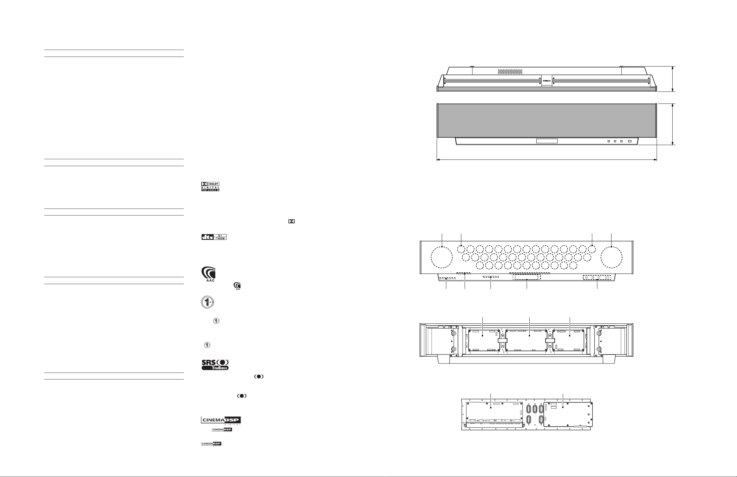
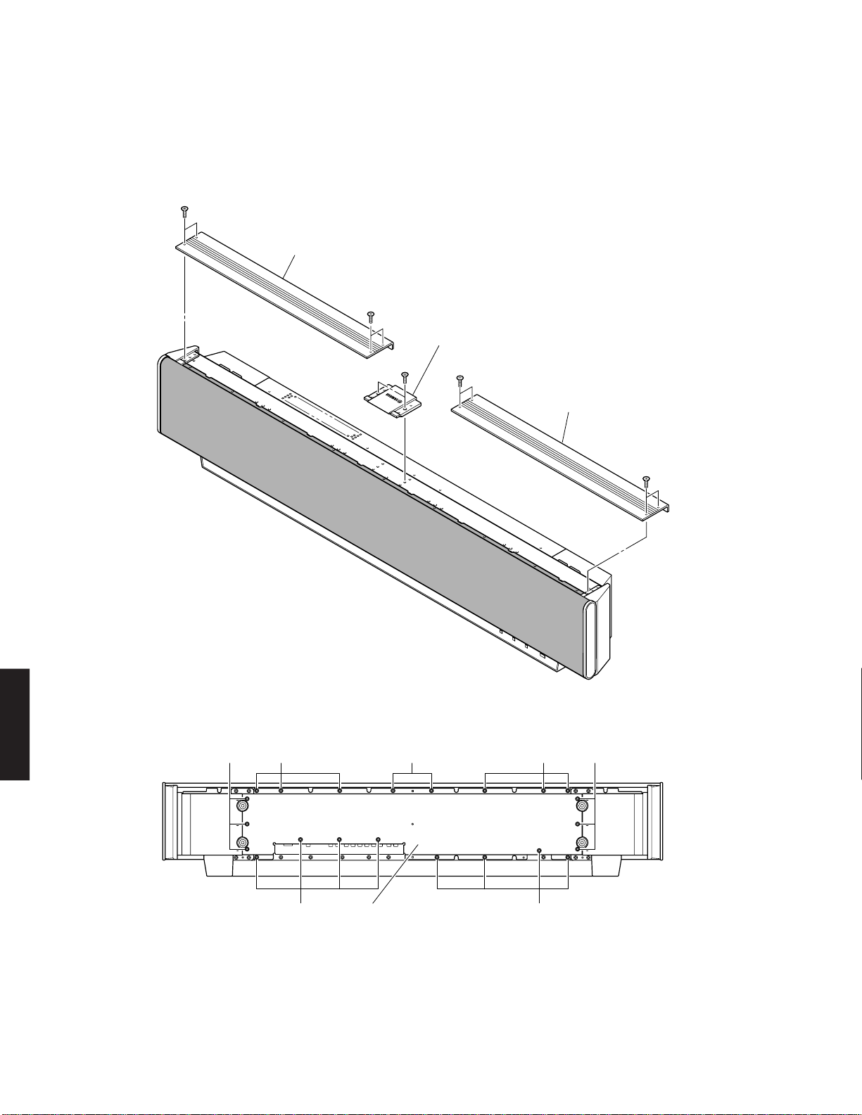
Yamaha YSP 1000 - Digital Sound Projector Five CH... User manual

SERVICE MANUAL
DIGITAL SOUND PROJECTOR
YSP-1000
■CONTENTS
TO SERVICE PERSONNEL .......................................... 2
FRONT PANEL .............................................................. 3
REAR PANELS .............................................................. 3
REMOTE CONTROL PANELS ...................................... 4
SPECIFICATIONS / 参考仕様 ........................................ 5
INTERNAL VIEW ........................................................... 5
SET MENU TABLE ........................................................ 6
SERVICE PRECAUTIONS /サービス時の注意事項 ..... 7
DISASSEMBLY PROCEDURES/分解手順 ........... 7~13
UPDATING FIRMWARE/
ファームウェアの書き込み ..................................... 14~24
SELF DIAGNOSIS FUNCTION (DIAG)/
自己診断機能(ダイアグ)..................................... 25~42
DISPLAY DATA ........................................................... 43
IC DATA ................................................................. 44~45
BLOCK DIAGRAM ................................................. 46~47
PRINTED CIRCUIT BOARD .................................. 48~58
PIN CONNECTION DIAGRAM .................................... 59
SCHEMATIC DIAGRAM ........................................ 61~68
PARTS LIST ........................................................... 69~90
REMOTE CONTROL.................................................... 91
YSP-1000 Packing Instruction / 梱包手順説明書 ........ 92
100967
IMPORTANT NOTICE
This manual has been provided for the use of authorized YAMAHA Retailers and their service personnel.
It has been assumed that basic service procedures inherent to the industry, and more specifically YAMAHA Products, are already
known and understood by the users, and have therefore not been restated.
WARNING: Failure to follow appropriate service and safety procedures when servicing this product may result in personal
injury, destruction of expensive components, and failure of the product to perform as specified. For these reasons,
we advise all YAMAHA product owners that any service required should be performed by an authorized
YAMAHA Retailer or the appointed service representative.
IMPORTANT: The presentation or sale of this manual to any individual or firm does not constitute authorization, certification or
recognition of any applicable technical capabilities, or establish a principle-agent relationship of any form.
The data provided is believed to be accurate and applicable to the unit(s) indicated on the cover. The research, engineering, and
service departments of YAMAHA are continually striving to improve YAMAHA products. Modifications are, therefore, inevitable
and specifications are subject to change without notice or obligation to retrofit. Should any discrepancy appear to exist, please
contact the distributor's Service Division.
WARNING: Static discharges can destroy expensive components. Discharge any static electricity your body may have
accumulated by grounding yourself to the ground buss in the unit (heavy gauge black wires connect to this buss).
IMPORTANT: Turn the unit OFF during disassembly and part replacement. Recheck all work before you apply power to the unit.
P.O.Box 1, Hamamatsu, Japan
2005 All rights reserved.
This manual is copyrighted by YAMAHA and may not be copied or
redistributed either in print or electronically without permission.
YSP-1000
When transporting this unit, be sure to use the unit’s packing materials and box so as to protect
it against any damage, in particular, dents in the front grille during transportation.
本機を輸送する場合、輸送時の破損(特に、フロントグリルのへこみ)等を防ぐために必ず専用の梱
包箱を使用してください。
'05.10

YSP-1000
2
YSP-1000
WARNING: CHEMICAL CONTENT NOTICE!
The solder used in the production of this product contains LEAD. In addition, other electrical/electronic and/or plastic (where
applicable) components may also contain traces of chemicals found by the California Health and Welfare Agency (and
possibly other entities) to cause cancer and/or birth defects or other reproductive harm.
DO NOT PLACE SOLDER, ELECTRICAL/ELECTRONIC OR PLASTIC COMPONENTS IN YOUR MOUTH FOR ANY REA-
SON WHATSOEVER!
Avoid prolonged, unprotected contact between solder and your skin! When soldering, do not inhale solder fumes or expose
eyes to solder/flux vapor!
If you come in contact with solder or components located inside the enclosure of this product, wash your hands before
handling food.
WALL
OUTLET
EQUIPMENT
UNDER TEST
AC LEAKAGE
TESTER OR
EQUIVALENT
INSULATING
TABLE
■TO SERVICE PERSONNEL
1. Critical Components Information
Components having special characteristics are marked s
and must be replaced with parts having specifications equal
to those originally installed.
2. Leakage Current Measurement (For 120V Models Only)
When service has been completed, it is imperative to verify
that all exposed conductive surfaces are properly insulated
from supply circuits.
●Meter impedance should be equivalent to 1500 ohms
shunted by 0.15µF.
●Leakage current must not exceed 0.5mA.
●Be sure to test for leakage with the AC plug in both polarities.
About Lead Free Solder / 無鉛ハンダについて
Side A
Side B
SMT
REFLOW
Process
MI
FLOW
Process
Solder Dip
無鉛ハンダにはいくつかの種類がありますが、修理時には
下記のような無鉛ハンダの使用を推奨します。
・Sn+Ag+Cu(錫+銀+銅)
・Sn+Cu(錫+銅)
・Sn+Zn+Bi(錫+亜鉛+ビスマス)
注意:
① 無鉛ハンダの融点温度は通常の鉛入りハンダに比べ30
〜40℃程度高くなっていますので、それぞれのハンダ
に合ったハンダごてをご使用ください。
② 鉛入りハンダを使わざるを得ない場合は、あらかじめ交
換する部品端子部やその周辺部の無鉛ハンダをすべて取
り除くか、あるいは無鉛ハンダと鉛入りハンダが十分に
溶けた状態となるようにハンダ付けしてください。
Among some types of lead free solder currently available,
it is recommended to use one of the following types for the
repair work.
•Sn + Ag + Cu (tin + silver + copper)
•Sn + Cu (tin + copper)
•Sn + Zn + Bi (tin + zinc + bismuth)
Caution:
1. As the melting point temperature of the lead free solder
is about 30°C to 40°C (50°F to 70°F) higher than that of
the lead solder, be sure to use a soldering iron suitable
to each solder.
2. If lead solder must be used, be sure to remove lead free
solder from each terminal section of the parts to be
replaced and from the area around it completely before
soldering, or make sure that the lead free solder and
lead solder melt together fully.
The P.C.B.s installed in this unit are soldered using the
following solder.
本機に搭載されている基板のハンダ付けに使用されている
ハンダは下記の通りです。
“CAUTION”
“F501: FOR CONTINUED PROTECTION AGAINST RISK OF FIRE, REPLACE ONLY WITH SAME TYPE 5A, 125V FUSE.”
CAUTION
F501: REPLACE WITH SAME TYPE 5A, 125V FUSE.
ATTENTION
F501: UTILISER UN FUSIBLE DE RECHANGE DE MEME TYPE DE 5A, 125V.
AMP P.C.B.
DSP P.C.B.
INPUT P.C.B.
OPERATION P.C.B.
SIDE A / A面
Lead Free Solder / 無鉛ハンダ
–
–
SIDE B / B面
Lead Free Solder / 無鉛ハンダ

YSP-1000
3
YSP-1000
■FRONT PANEL
■REAR PANELS
J model
IR OUT
OPTIMIZER MIC
(YAPO)
U, C,T, K, A, B, G, L, V models
J model
BOTTOM VIEW
U, C models T model K model
A model B, G models
V model J model
L model

YSP-1000
4
YSP-1000
■REMOTE CONTROL PANELS
電源 電源
AV TV
テレビビデオDVD
マクロ入力1AUX
YSP
5ビーム
ステレオ ターゲット AAC音声多重
1
4
1211/+1010/0
7
3ビーム
音量モード
サラウンドオフ
シネマDSP
CHレベル メニュー
テスト
消音 テレビ入力切替テレビ消音
コードセット
チャンネル音量 テレビ音量
戻る
決 定
スポーツ
映画音楽
ST+3ビーム
スリープ
チューナー
入力モード
入力2
テレビ
電源
89
56
23
WF72980
RRC4001-2603EM
(U model)
WF75640
TV
POWER
AV
POWER
STANDBY/ON
TV
STBVCRDVD
TV
2
1
STEREO
SLEEP
CH LEVEL MENU
RETURN
TEST
TV VOL
VOLUME
MUTE TV INPUT TV MUTE
ENTER
SURROUND
OFF
CODE SET
SPORTS
3
456
789
0
+10
5BEAM
ST+3BEAM
3BEAM
TARGET
MUSIC MOVIE VOL MODE
INPUTMODE
MACROINPUT2INPUT1
AUX
YSP
CINEMA DSP
CH
WF72990
TV
POWER
AV
POWER
STANDBY/ON
TV
STBVCRDVD
TV
2
1
STEREO
SLEEP
CH LEVEL MENU
RETURN
TEST
TV VOL
VOLUME
MUTE TV INPUT TV MUTE
ENTER
SURROUND
OFF
CODE SET
SPORTS
3
456
789
0
+10
5BEAM
ST+3BEAM
3BEAM
TARGET
MUSIC MOVIE VOL MODE
INPUTMODE
MACROINPUT2INPUT1
AUX
YSP
CINEMA DSP
CH
RRC4001-2601EM
(C, T, K, A, B, G, L, V models)
RRC4001-2602EM
(J model)

YSP-1000
5
■INTERNAL VIEW
• DIMENSIONS/寸法図
■SPECIFICATIONS / 参考仕様
Manufactured under license from Dolby Laboratories.
“Dolby”, “Pro Logic”, and the double-D symbol are trademarks of
Dolby Laboratories.
ドルビーラボラトリーズからの実施権により製造されています。「ドル
ビー」、「PROLOGIC」およびダブルD記号 は、ドルビーラボラト
リーズの商標です。
“DTS”, and “Neo:6” are trademarks of Digital Theater Systems, Inc.
DTS、DTSデジタルサラウンドおよびNeo:6はデジタルシアターシス
テムズの登録商標です。
AACロゴマーク はドルビーラボラトリーズの商標です。
Manufactured under license from 1 Ltd. World-wide patents applied for.
The “ ” logo and “Digital Sound Projector” are trademarks of 1
Ltd.
本デジタル・サウンド・プロジェクターは、全世界へ特許申請中の英
国1Ltdからライセンス許諾を得た製品です。
ロゴと、デジタル・サウンド・プロジェクターは1Ltdの商標
です。
TruBass, SRS and the “ ” symbol are registered trademarks
of SRS Labs, Inc. TruBass technology is incorporated under
license from SRS Labs, Inc.
TruBass、SRSと 記号はSRSLab,Inc.の商標です。
TruBass技術はSRSLabs,Inc.からのライセンスに基づき製品化され
ています。
The “ ”logo and “Cinema DSP” are registered trademarks of
YAMAHA Corporation.
ロゴおよび「シネマDSP」、「CINEMADSP」は、ヤマハ
株式会社の登録商標です。
118 (4-11/16")
194 (7-5/8")
1030 (40-9/16")
Unit : mm(inch)
単位: mm(インチ)
63 4 5 7
1DRIVER, WOOFER
2DRIVER, TWEETER
3OPERATION (3) P.C.B.
4OPERATION (4) P.C.B.
5INPUT (3) P.C.B.
6OPERATION (1) P.C.B.
7OPERATION (2) P.C.B.
8AMP (2) P.C.B.
9DSP P.C.B.
0AMP (1) P.C.B.
AINPUT (2) P.C.B.
BINPUT (1) P.C.B.
FRONT VIEW
REAR VIEW
SHIELD UNIT
2
2 11
8 9
A B
0
■Amplifier Section/アンプ部
Maximum Power / 実用最大出力 (EIAJ)
Woofer [3 ohms, 100 Hz, 10% THD] ................................ 20 W/ch
Tweeter [4 ohms, 1 kHz, 10% THD] ................................... 2 W/ch
Total Maximum Output Power / 総合最大出力
.............................................................................................. 120 W
Minimum RMS Output Power / 定格出力
Woofer [3 ohms, 100 Hz, 0.9% THD] ............................... 14 W/ch
Tweeter [4 ohms, 1 kHz, 0.9% THD] ............................... 1.7 W/ch
Input Sensitivity/Impedance / 入力感度/インピーダンス
Analog Input ....................................................... 1.0 V / 32 k-ohms
Maximum Input Signal / 最大許容入力 [1 kHz, 0.5% THD]
Analog Input .............................................................. 2.2 V or more
Output Level/Impedance / 出力電圧/出力インピーダンス
Woofer PRE OUT ............... 1.5 V / 1.1 k-ohms (less then 120 Hz)
Total Harmonic Distortion / 全高調波歪率 [1 W]
Woofer [100 Hz] .......................................................... 0.2% or less
Tweeter [1 kHz] ........................................................... 0.1% or less
■Video Section/ビデオ部
Output Level
Composite Video ................................................... 1 Vp-p/75 ohms
Component Video Y ............................................. 1 Vp-p/75 ohms
Pb, Pr ................................... 0.5 Vp-p/75 ohms
Frequency Characteristics
Composite Video ........................................................ 5 Hz-10 MHz
Component Video ...................................................... 5 Hz-60 MHz
■Speaker Section/スピーカー部
Type / 型式 ............................................. 2-Way Acoustic suspension
Magnetic Shielding Type
Driver / スピーカーユニット
Woofer ................. 11 cm (4.5") Cone Magnetic Shielding Type x 2
Tweeter ................ 4 cm (1.5") Cone Magnetic Shielding Type x 40
Frequency Response / 再生周波数帯域
............................................................................... 55 Hz to 20 kHz
Crossover Frequency / クロスオーバー周波数
Beam Channel ...................................................................... 350 Hz
Stereo Channel ...................................................................... 1 kHz
■Input/Output/入力/出力
Input Jack / 入力端子
AUDIO (Analog) .......................................................................... x 2
AUDIO (Optical) .......................................................................... x 2
AUDIO (Coaxial) .......................................................................... x 1
VIDEO (Composite)..................................................................... x 3
VIDEO (Component) ................................................................... x 2
OPTIMIZER MIC ......................................................................... x 1
Output Jack /出力端子
SUBWOOFER ............................................................................. x 1
VIDEO (Composite)..................................................................... x 1
VIDEO (Component) ................................................................... x 1
Remote IN/OUT /リモート入出力
RS-232C INPUT ......................................................................... x 1
REMOTE IN (External Wired-IN) ............................................... x 1
IR pass-Through Out .................................................................. x 1
■General/総合
Power Supply/電源電圧
U, C models .......................................................... AC 120 V, 60 Hz
T model ................................................................. AC 220 V, 50 Hz
K model................................................................. AC 220 V, 60 Hz
A model................................................................. AC 240 V, 50 Hz
B, G models .......................................................... AC 230 V, 50 Hz
L model .................................................... AC 220-240 V, 50/60 Hz
V model.................................................... AC 110-120 V, 50/60 Hz
J model ............................................................ AC 100V, 50/60 Hz
Power Consumption/消費電力
............................................................................................... 50 W
Standby Power Consumption (Reference Data)/待機時消費電力(参考値)
................................................................................... 0.1 W or less
Dimensions/寸法 (W x H x D)
...................... 1030 x 194x 118 mm (40-9/16" x 7-5/8" x 4-11/16")
Weight/質量
...................................................................... 13 kg (28 lbs. 10 oz.)
Finish/仕上げ
Silver color ............................... U, C, T, K, A, B, G, L, V, J models
Black color ............................... U, C, T, K, A, B, G, L, V, J models
Accessories/付属品
Remote Control x 1, Batteries (Manganese Dry) x 2, Video Pin Cable
x 1, Audio Pin Cable x 1, Digital Audio Pin Cable x 1, Optical Cable x
1, Fastener x 4, Optimizer Microphone x 1, Cardboard Microphone
Stand x 1, Power Cable x 1
U .......... U.S.A. model C ...... Canadian model
T .......... Chinese model K ...... Korean model
A .......... Australian model B ...... British model
G .......... European model L ....... Singapore model
V .......... Taiwan model J ....... Japanese model
* Specifications are subject to change without notice due to product
improvements.
※ 参考仕様および外観は予告なく変更されることがあります。

YSP-1000
6
■SET MENU TABLE / セットメニュー
A) TONE CONTROL
B) BEAM LEVEL
C) SWFR SET
D) MUTE LEVEL
E) AUDIO DELAY
F) ROOM EQ
G) D-RANGE
1 SOUND MENU
2 BEAM MENU
A) PARAMETERS
a) HORIZ. ANGLE
b) VERT. ANGLE
c) BEAM LENGTH
d) FOCAL LENGTH
e) TREBLE GAIN
IMAGE
LEFT
RIGHT
3 INPUT MENU
A) INPUT ASSIGN
B) BEAM ADJ *9
H.ANGLE FL -90 ~ 0 ~ +90deg, 1 step *5
H.ANGLE FR -90 ~ 0 ~ +90deg, 1 step *5
H.ANGLE C -90 ~ 0 ~ +90deg, 1 step *5
H.ANGLE SL -90 ~ 0 ~ +90deg, 1 step *5
H.ANGLE SR -90 ~ 0 ~ +90deg, 1 step *5
V.ANGLE FL -45deg ~ +45deg *5
V.ANGLE FR 1deg step *5
V.ANGLE C 1deg step *5
V.ANGLE SL 1deg step *5
V.ANGLE SR 1deg step *5
B.LEN FL 0.3 ~ 24.0 [7.1] m, 0.1 step/1.0 ~ 80.0ft, 0.5 step
B.LEN FR 0.3 ~ 24.0 [7.1] m, 0.1 step/1.0 ~ 80.0ft, 0.5 step
B.LEN C 0.3 ~ 24.0 [3.0] m, 0.1 step/1.0 ~ 80.0ft, 0.5 step
B.LEN SL 0.3 ~ 24.0 [10.0] m, 0.1 step/1.0 ~ 80.0ft, 0.5 step
B.LEN SR 0.3 ~ 24.0 [10.0] m, 0.1 step/1.0 ~ 80.0ft, 0.5 step
F.L. FL -1.0 ~ +13.0 [+6.0] m, 0.1 step/-3.5 ~ +43.5ft, 0.5 step
F.L. FR -1.0 ~ +13.0 [+6.0] m, 0.1 step/-3.5 ~ +43.5ft, 0.5 step
F.L. C -1.0 ~ +13.0 [-1.0] m, 0.1 step/-3.5 ~ +43.5ft, 0.5 step
F.L. SL -1.0 ~ +13.0 [+13.0] m, 0.1 step/-3.5 ~ +43.5ft, 0.5 step
F.L. SR -1.0 ~ +13.0 [+13.0] m, 0.1 step/-3.5 ~ +43.5ft, 0.5 step
TRBL FL -12.0 ~ [0] ~ +12.0 dB, 0.5 step
TRBL FR -12.0 ~ [0] ~ +12.0 dB, 0.5 step
TRBL C -12.0 ~ [0] ~ +12.0 dB, 0.5 step
TRBL SL -12.0 ~ [0] ~ +12.0 dB, 0.5 step
TRBL SR -12.0 ~ [0] ~ +12.0 dB, 0.5 step
OFF, [ON]
[0] ~ 95% (OFF), 5% step *5
[0] ~ 95% (OFF), 5% step *5
[TV], VIDEO
DVD, [AUX] U, C, T, K, A, B, G, L, V models
[DVD], AUX J model
[DVD], AUX U, C, T, K, A, B, G, L, V models
DVD, [AUX] J model
[TV], VCR U, C, T, K, A, B, G, L, V models
[TV], VCR J model
[DVD], AUX U, C, T, K, A, B, G, L, V models
[DVD], AUX J model
DVD, [AUX] U, C, T, K, A, B, G, L, V models
[DVD], AUX J model
-6.0 ~ 0 [-3.0] dB, 0.5 step
_ DVD *11
-2, -1, [0]
DISPLAY OFF, -3, -2, -1, [0] *12
-5 ~ [0] ~ +5, 1 step *13
[BLUE], GRAY
U, C, T, K, A, B, G, L, V models
C) IMAGE LOCTN
-12.0 ~ [0] ~ +12.0 dB, 0.5 step
· · · · | · · · · -10.0 ~ 0 ~ +10.0 dB, 0.5 step *5
SWFR, [FRONT]
80, [100], 120 (Hz)
-20 ~ [0] (dB)
0.3 ~ 15.0 [3.0] m, 0.1 step
1.0 ~ 50.0 [7.0] ft, 0.5 step
[MUTE], -20dB
[0] ~ 160mS, 1 step
[SHELF], WALL
[NORMAL], HI ECHO
MIN, STD, [MAX]
POSITION
INSTALLED HEIGHT
RM WDTH
(C: LEFT WALL)
RM LGTH
(C: RIGHT WALL)
USER POS
L WALL *4
[FLAT], ANGLE
0.0 ~ 3.0m 0.1 step
0.0 ~ 10.0ft 0.5 step
2.0 ~ 12.0m 0.1 step *6
6.5 ~ 40.0ft 0.5 step
2.0 ~ 12.0m 0.1 step *7
6.5 ~ 40.0ft 0.5 step
2.0 ~ 9.0m 0.1 step *8
6.5 ~ 30.0ft 0.5 step
0.6 ~ 11.4m 0.1 step
2.0 ~ 38.0ft 0.5 step
TREBLE
BASS
FR
C
SL
SR
SWFR
BASS OUT
CROSS OVER
LFE LEVEL
DISTANCE
MUTE LVL
DELAY
MOUNTING
RFLCT
D-RANGE
OPT (1)
OPT (2) *10
COAX *10
COMPONENT IN (1)
COMPONENT IN (2)
COMPOSITE IN
B) INPUT MODE
C) INPUT TRIM
D) INPUT RENAME
*1 ..... Displayed only after executing AUTO SETUP once or more. /
*2 ..... Displayed only when BASS OUT is set to SWFR. /
*4 ..... Displayed only for the wall mounting setting; distance from the wall on the left side to the user. /
*5 ..... Test tone output. /
*6 ..... Distance in the lateral direction of the room. (length of the wall on the left side of the user) /
*7 ..... Distance in the longitudinal direction of the room. (length of the wall on the right side of the user) /
*8 ..... Distance from this unit to the user. /
*9 ..... Selectable items are limited depending on BEAM MODE. /
*10 ... Priority given to COAXIAL when set to the same input. /
*11 ... MAX 8 Character. / U, C, T, K, A, B, G, L, V models)
*12 ... OFF = Brightness of STANDARD DIMMER. /
*13 ... + direction is downward. /
4
DISPLAY MENU
A) DIMMER SET
B) OSD SET
C) UNIT SET
STD DIMMER
AT DIMMER
OSD SHIFT
OSD COLOR
METERS, FEET
[AUTO], LAST
TV ANALOG
TV OPTICAL
VCR/VIDEO ANALOG
AUX/DVD OPTICAL
AUX/DVD COAXIAL
DVD ->
• MANUAL SETUP
1 ROOM TYPE ?
2 INST POS ?
3 ROOM SIZE ?
4 SETUP OK ?
• BASIC SETUP
SQUARE, RECTANGLE
SQUARE: LEFT, CENTER, RIGHT, CORNER
RECTANGLE: WIDE·LEFT, CENTER, RIGHT
CORNER·RIGHT, LEFT
NARROW·LEFT, CENTER, RIGHT
SMALL, MID, LARGE
YES, NO
Dialogue /
INST
MOUNT
RFLCT
INST
MOUNT
RFLTC
A)
BEAM+SOUND
OPT
B) BEAM OPT only
C) SOUND OPT
only
PARALLEL, ANGLE
SHELF, WALL
NORMAL, HI ECHO
PARALLEL, ANGLE
SHELF, WALL
NORMAL, HI ECHO
CATEGORY 1 MAIN MENU 2 SUB MENU 3 SELECT MENU 4 VALUE [INITIAL]
1) LOAD
2) SAVE
USER1, USER2, USER3
USER1, USER2, USER3
• AUTO SETUP
LOAD SEL :
SAVE SEL :
• MEMORY

YSP-1000
7
YSP-1000
(番号順に部品を取り外してください。)
分解・組立時の注意:
・
AC電源コンセントから、電源コードを抜いてください。
・
やわらかい布等を敷いて その上で作業を行ってください。
・ フロントグリル等で怪我をする恐れがあります。十分
注意してください。
・ ネジを閉め忘れると、エアー漏れをすることがあります。
ネジの個数及び位置を確認し、取り付けてください。
・ 取り付けの際、ケーブル等を部品の隙間に挟み込むこ
とがあります。十分注意してください。
・ 取り外したスピーカーユニット(ツイーター)はすべて
決められた位置に取り付けてください。
■DISASSEMBLY PROCEDURES / 分解手順
(Remove parts in the order as numbered.)
Cautions for disassembly and reassembly :
• Disconnect the power cable from the AC outlet.
• Spread soft cloth or the like and perform the work on it.
• Use full care as you may be injured by the front grille
or other part.
• All screws must be tightened securely to prevent air
leakage. Check the number of screws and their
positions when installing them.
• When installing parts, be careful not to have anything
such as cables caught between other parts.
• Make sure that all the removed driver (tweeter) parts
are reinstalled at specified positions.
■SERVICE PRECAUTIONS / サービス時の注意事項
安全対策
・ この製品の内部には高電圧部分があり危険です。修理の
際は、絶縁性の手袋を使用するなどの安全対策を行って
ください。
・ INPUT(1)P.C.B.のC523には電源をOFFにした後も電
荷が残り、高電圧が維持されており危険です。
修理作業前に放電用抵抗(5kΩ/10W)をC523の端子間
に接続して放電してください。
(放電用抵抗の接続箇所はP.52PRINTED CIRCUIT
BOARD[INPUT(1)P.C.B.]およびP.67SCHEMATIC
DIAGRAM[INPUT2/2]に記載しています。)
Safety measures
• Some internal parts in this product contain high voltages
and are dangerous. Be sure to take safety measures
during servicing, such as wearing insulating gloves.
• Note that C523 on the INPUT (1) P.C.B. is dangerous
even after the power is turned off because an electric
charge remains and a high voltage continues to exist
there.
Before starting any repair work, perform discharge by
connecting a discharge resistor (5 k-ohms/10 W) between
C523 terminals.
(For the discharge resistor connection points, refer to p.52
“PRINTED CIRCUIT BOARD [INPUT (1) P.C.B.]” and p.67
“SCHEMATIC DIAGRAM [INPUT 2/2]”)

YSP-1000
8
YSP-1000
Fig. 2
3333
33
3
Rear Panel
1. Removal of Top Panels and Plate/Top
a. Remove 8 screws (1). (Fig. 1)
b. Remove 2 Top Panels.
c. Remove 2 screws (2). (Fig. 1)
d. Remove the Plate/Top.
1
1
1
1
2
Top Panel
Top Panel
Plate/ Top
Fig. 1
1. トップパネル、プレート/トップの外し方

YSP-1000
9
YSP-1000
2. Removal of Shield Unit
a. Remove 22 screws (3). (Fig. 2)
b. Remove the Rear Panel.
c. Remove 18 screws (4). (Fig. 3)
d. Remove CB2, CB3, CB4, CB504, CB507 and CB508.
(Fig. 3)
e. Remove 5 Pad LN’s.
f. Remove the Shield Unit.
2. シールドユニットの外し方
3
4
Fig. A
Fig. 3
When checking the P.C.B. :
•The Shield Unit removed from the unit does not work
because its grounding is loose. Be sure to connect the
ground of the Shield Unit to the chassis or GND with a
lead wire or the like. (Fig. A)
•Reconnect all cables (connectors) that have been
disconnected.
•When connecting the cable, use care for the polarity.
P.C.B.チェックをする場合には
CB3
CB2 CB508
CB504
CB507
CB4
Shield Unit
Pad LN
4 4 4
44
4
Shield Unit
Front Panel Unit
DSP P.C.B.AMP (R) P.C.B. AMP (L) P.C.B.
Earth (lead wire)

YSP-1000
10
YSP-1000
Fig. 4
Fig. 5
3. INPUT(1)、(2)P.C.B.の外し方
567
89
3. Removal of INPUT (1), (2) P.C.B.
a. Remove 6 screws (5), 8 screws (6) and 2 jack screws (7).
(Fig. 4)
b. Remove CB4. (Fig. 4)
c. Remove the INPUT (2) P.C.B..
d. Remove 6 screws (8) and 2 screws (9). (Fig. 4)
e. Remove the INPUT (1) P.C.B..
4. DSPP.C.B.、AMP(L)、(R)P.C.B.の外し方
0
A
4. Removal of DSP P.C.B., AMP (L), (R) P.C.B.
a. Remove 4 screws (0). (Fig. 5)
b. Remove CB6, CB7, CB8 and CB9. (Fig. 5)
c. Remove DSP P.C.B..
d. Remove 8 screws (A). (Fig. 5)
e. Remove CB507, CB509, CB510, CB511, CB512, CB707,
CB709, CB710, CB711 and CB712. (Fig. 5)
f. Remove the AMP (L), (R) P.C.B..
CB4
Shield Unit
8
576 89
5
INPUT (1) P.C.B.INPUT (2) P.C.B.
0
0
CB510
CB7
CB6
CB709 CB710
CB512 CB511 CB507
A
A
A
A
CB509 CB502
CB8 CB9
CB707CB702 CB712CB711
DSP P.C.B. AMP (L)P.C.B.AMP (R) P.C.B.
R ch L ch

YSP-1000
11
YSP-1000
5. フロントパネルユニットの外し方
B
C
D
5. Removal of Front Panel Unit
a. Remove 4 screws (B). (Fig. 6)
b. Remove 2 Cover FP’s.
c. Remove CB3 and CB303. (Fig. 6)
d. Remove 4 screws (C). (Fig. 6)
e. Remove 2 Cover BTM’s.
f. Remove 12 screws (D). (Fig. 6)
g. Remove the Front Panel Unit.
Fig. 7
Fig. 8
Fig. 6
7. Removal of Driver (Tweeter)
a. Remove 12 screws (H). (Fig. 8)
b. Remove 2 Supports/DSP and 2 Supports/DSP C. (Fig. 9)
c. Remove the Sound absorbing material.
d. Remove 2 screws/piece marked (I). (Fig. 10)
e. Remove the Driver (Tweeter).
7. スピーカーユニット(ツイーター)の外し方
H
I
6. OPERATION(1)、(3)、(4)P.C.B.の外し方
E
F
G
6. Removal of OPERATION (1), (3), (4) P.C.B.
a. Remove 6 screws (E). (Fig. 7)
b. Remove CB1. (Fig. 7)
c. Remove the OPERATION (1) P.C.B..
d. Remove 4 screws (F). (Fig. 7)
e. Remove CB301. (Fig. 7)
f. Remove the OPERATION (3) P.C.B..
g. Remove 4 screws (G). (Fig. 7)
h. Remove CB302. (Fig. 7)
i. Remove the OPERATION (4) P.C.B..
CD DDBB
D
Front Panel Unit
Cover FP
CB3 CB303
Cover BTM
Cover BTM
Cover FP
C
F GGE
OPERATION (3) P.C.B.
OPERATION (4) P.C.B.OPERATION (1) P.C.B.
CB1
CB301
CB302
H H H
H H H H
H
TOP
BOTTOM

YSP-1000
12
YSP-1000
Installation of Driver (Tweeter)
Caution : Make sure that all the removed Driver (tweeter)
parts are reinstalled at specified positions.
(Fig. B)
スピーカーユニット(ツイーター)の取り付け方
注意:
Fig. 10
Fig. B
I
Sound Absorber
Support/ DSP
Support/ DSP
Support/ DSP C
Fig. 9
A1
B1
A2
B2
C1
A3
B3
C2
A4
B4
C3
A5
B5
C4
A6
B6
C5
A7
B7
C6
A8
B8
C7
A9
B9
C8
A10
B10
C9
A11
B11
C10
A12
B12
C11
A13
B13
A14
B14
A15
REAR VIEW
Rch side
Lch side
CB510
CB512 CB511 CB709 CB710
CB509 CB711 CB712
Lch side / Lch側
Pin No. / ピンNo. CB509
1 –2
3 –4
5 –6
7 –8
9 –10
C5
B6
C4
B5
C3
B4
C2
B3
C1
B2
C9
C8
C7
B8
C6
B13
C11
B12
C10
B11
A9
B9
A10
B10
A11
A12
A13
A14
B14
A15
A1
B1
A2
A3
A4
CB510 CB511 CB512 CB709 CB710 CB711 CB712
Rch side / Rch側
A5
A6
A7
B7
A8

YSP-1000
13
YSP-1000
8. Removal of Driver (Woofer)
a. Remove 4 screws (J). (Fig. 11)
b. Remove the Side Covers L/R.
c. Remove the Plate/Cover.
d. Remove 4 screws (K). (Fig. 11)
e. Remove the Plate/Side.
f. Remove 18 screws (L). (Fig. 11)
g. Remove the Front Grille.
h. Remove 16 screws (M). (Black Color model) (Fig. 11)
i. Remove the Grille Ass’y. (Black Color model)
j. Remove 8 screws (N). (Fig. 11)
k. Remove the Driver (Woofer).
8. スピーカーユニット(ウーファー)の外し方
J
K
L
M
N
Fig. 11
L
L
M
M
N
N
J
J
K
K
K
K
Side Cover L
Side Cover R
Plate Side
Plate Side
Plate Cover
Plate Cover
Front Grille
Grille Ass'y (Black Color model)
ASSY (Black Color model)
Driver, Woofer
Driver, Woofer

YSP-1000
14
YSP-1000
●操作前の準備と注意
•RS232C cross cable “D-sub 9 pin female”
(Specifications)
Pin No.2 RxD Pin No.2 RxD
Pin No.3 TxD Pin No.3 TxD
Pin No.5 GND Pin No.5 GND
Pin No.7 RTS Pin No.7 RTS
Pin No.8 CTS Pin No.8 CTS
●Preparation and precautions before starting
the operation
•Download DSP_FLASHER(YSP).exe and
spDownloader_2_0_x_xxx.exe from the specified
source to the PC being used.
•Prepare the above specified RS232C cross cable.
•While writing, keep the other application software on
the PC closed. It is also recommended to keep the
software on the task tray closed as well.
■UPDATING FIRMWARE / ファームウェアーの書き込み
●必要なツール
After replacing the following parts with the replacement
parts, update the firmware.
IC11 of P.C.B. ASS’Y DSP : X6962B00
... Writing of DSP
IC17 of P.C.B. ASS’Y DSP : X7073B00
... Writing of DSP APPLICATION / SPID
IC26 of P.C.B. ASS’Y DSP : X6894A00
... Writing of CPU
●Required tools
•DOS/V machine, OS: Windows 98/2000/Me/XP, PC
with a serial port (RS232C)
•Program upgrading program
There are 2 program upgrading programs.
Writing of CPU : DSP_FLASHER(YSP).exe
Writing of DSP : DSP_FLASHER(YSP).exe
Writing of DSP APPLICATION / SPID
: spDownloader_2_0_x_xxx.exe.
•Firmware
* Be sure to put following 4 firmwares in the same
folder.
CPU .................................................
DSP .......................................
DSP APPLICATION
......................... ysp2app_YSP2-0_xxxxx_.hex
SPID .................................................. Y10xxxxxx.bin

YSP-1000
15
YSP-1000
●操作方法
●Operation Procedure
Writing of CPU
1. Install DSP_FLASHER(YSP).exe into the PC.
2. Before turning on the power to YSP-1000 and PC,
connect between RS232C ports with the RS232C cable
(cross cable). (Fig. 1)
Fig. 2
BOTTOM VIEW
Reset Switch
Fig. 1
BOTTOM VIEW
RS-232C Port
RS-232C Cable
Reset Switch
3. While pressing the reset switch of YSP-1000, connect
the power cable to the AC outlet. (Fig. 1, 2)
* Use a fine tipped pin or the like to push the reset
switch.
4. Start up DSP_FLASHER(YSP).exe, the screen will
appear as shown below.

YSP-1000
16
YSP-1000
・MOTFILE
・RS232C
5. Select the data to be transmitted and port.
· MOT FILE
Select “SA2_10Vx.mot”.
· RS232C
Select the port of RS-232C.
Select the port of RS-232C
接続しているRS-232Cポートを選択します
Press this button to open the window
このボタンを押すとウィンドウが開きます
Select the firmware
ファームウェアを選択します
* The port selection varies depending on OS of the PC.
Windows 98/2000/Me .......... COM1~4
Windows XP ......................... COM1~2
As no port other than the above can be used, se-
lect the port using the setting of the PC.
Press this button to start writing
このボタンを押すと
書き込みが開始されます
During downloading
書き込み中
6. Press the [E.P.] button and start writing.

YSP-1000
17
YSP-1000
3. Start up DSP_FLASHER(YSP).exe, the screen will
appear as shown below.
Writing of DSP
1. Install DSP_FLASHER(YSP).exe into the PC.
2. Before turning on the power to YSP-1000 and PC,
connect between RS232C ports with the RS232C cable
(cross cable). (Fig. 1)
7. When the program transmission is completed, the
screen appears as shown below.
The press the [OK] button to end the procedure.
8. Disconnect the power cable of YSP-1000 from the AC
outlet.

YSP-1000
18
YSP-1000
・DSPHEXFILE
・RS232C
4. Select “YSP DSP”Tag.
5. Select the data to be transmitted and port.
· DSP HEX FILE
Select “YSPx00_verxxxx.hex”.
· RS232C
Select the port of RS-232C.
* The port selection varies depending on OS of the PC.
Windows 98/2000/Me .......... COM1~4
Windows XP ......................... COM1~2
As no port other than the above can be used, se-
lect the port using the setting of the PC.
Select the port of RS-232C
接続しているRS-232Cポートを選択します
Select YSP DSP
YSPDSPを選択します
Press this button to open the window
このボタンを押すとウィンドウが開きます
Select the firmware
ファームウェアを選択します
Press this button
このボタンを押します
6. Press the [RDY] button.

YSP-1000
19
YSP-1000
8. When the program transmission is completed, the
screen appears as shown below.
Change OFF to ON
7. Connect the power cable of YSP-1000 to the AC outlet.
While pressing the “VOL+”key and “VOL-”key of the
YSP-1000, press the “STANDBY/ON”key of the
remote control to activate the DIAG function.
1Using the “UP”or “DOWN”key of the remote control,
select the DIAG menu in the figure below.
2Using the “LEFT”or “RIGHT”key of the remote
control, select the DIAG sub-menu in the figure
below.
3Using the “ENTER”key of the remote control, make
a change as shown below.
During downloading
書き込み中

YSP-1000
20
YSP-1000
9. Check the SUM.
After downloading successfully, the value of “SUM from
SET”is appeared.
The procedure is completed when the value is obtained
for “SUM from FILE”and “SUM from SET”.
Confirm the value of SUM
SUM値を確認します
10
.Press the “STANDBY/ON”key of the YSP-1000 to turn
off the power.
Other manuals for YSP 1000 - Digital Sound Projector Five CH...
2
This manual suits for next models
10
Table of contents
Other Yamaha Digital Sound Projector manuals