Yamaha Soavo-900SW User manual

SERVICE MANUAL
This manual has been provided for the use of authorized YAMAHA Retailers and their service personnel.
It has been assumed that basic service procedures inherent to the industry, and more specifically YAMAHA Products, are already
known and understood by the users, and have therefore not been restated.
WARNING: Failure to follow appropriate service and safety procedures when servicing this product may result in personal
injury, destruction of expensive components, and failure of the product to perform as specified. For these reasons,
we advise all YAMAHA product owners that any service required should be performed by an authorized YAMAHA
Retailer or the appointed service representative.
IMPORTANT: The presentation or sale of this manual to any individual or firm does not constitute authorization, certification or
recognition of any applicable technical capabilities, or establish a principle-agent relationship of any form.
The data provided is believed to be accurate and applicable to the unit(s) indicated on the cover. The research, engineering, and service
departments of YAMAHA are continually striving to improve YAMAHA products. Modifications are, therefore, inevitable and
specifications are subject to change without notice or obligation to retrofit. Should any discrepancy appear to exist, please contact the
distributor's Service Division.
WARNING: Static discharges can destroy expensive components. Discharge any static electricity your body may have
accumulated by grounding yourself to the ground buss in the unit (heavy gauge black wires connect to this buss).
IMPORTANT: Turn the unit OFF during disassembly and part replacement. Recheck all work before you apply power to the unit.
IMPORTANT NOTICE
101027
SERVICE MANUAL
REPAIR PROCEDURES / 修理手順 .......................... 11–14
DC OFFSET ADJUSTMENT / DCオフセット調整 ...........
14–15
IC DATA ......................................................................16
BLOCK DIAGRAM......................................................17
PRINTED CIRCUIT BOARDS ..............................18–20
SCHEMATIC DIAGRAMS ....................................21–22
REPLACEMENT PARTS LIST.............................23–34
REMOTE CONTROL ..................................................35
■ CONTENTS
TO SERVICE PERSONNEL......................................... 2
FRONT PANEL .............................................................3
REAR PANELS.........................................................3–5
REMOTE CONTROL PANEL.......................................6
SPECIFICATIONS / 参考仕様 ................................................ 6
DIMENSIONS ................................................................7
INTERNAL VIEW ..........................................................7
DISASSEMBLY PROCEDURES / 分解手順..............8–10
Soavo-900SW
SUBWOOFER SYSTEM
© 2006 YAMAHA CORPORATION. All rights reserved.
This manual is copyrighted by YAMAHA and may not be copied or
redistributed either in print or electronically without permission.
’06.09
POWER
STANDBY
SLEEP
PHASE
MEMORY
PRESET
HIGH CUT VOLUME
231
B.A.S.S.
WH64300
Soavo-900SW

2
Soavo-900SW
Soavo-900SW
■TO SERVICE PERSONNEL
1. Critical Components Information
Components having special characteristics are marked Z
and must be replaced with parts having specifications equal
to those originally installed.
2. Leakage Current Measurement (For 120V Models Only)
When service has been completed, it is imperative to verify
that all exposed conductive surfaces are properly insulated
from supply circuits.
●Meter impedance should be equivalent to 1500 ohms
shunted by 0.15µF.
●Leakage current must not exceed 0.5mA.
●Be sure to test for leakage with the AC plug in both
polarities.
AC LEAKAGE
TESTER OR
EQUIVALENT
EQUIPMENT
UNDER TEST
INSULATING
TABLE
WALL
OUTLET
WARNING: CHEMICAL CONTENT NOTICE!
The solder used in the production of this product contains LEAD. In addition, other electrical/electronic and/or
plastic (where applicable) components may also contain traces of chemicals found by the California Health and
Welfare Agency (and possibly other entities) to cause cancer and/or birth defects or other reproductive harm.
DO NOT PLACE SOLDER, ELECTRICAL/ELECTRONIC OR PLASTIC COMPONENTS IN YOUR MOUTH FOR
ANY REASON WHATSOEVER!
Avoid prolonged, unprotected contact between solder and your skin! When soldering, do not inhale solder fumes
or expose eyes to solder/flux vapor!
If you come in contact with solder or components located inside the enclosure of this product, wash your hands
before handling food.
“CAUTION”
“F1 : FOR CONTINUED PROTECTION AGAINST RISK OF FIRE, REPLACE ONLY WITH SAME TYPE 12A, 125V FUSE.”
CAUTION
F1 : REPLACE WITH SAME TYPE 12A, 125V FUSE.
ATTENTION
F1 : UTILISER UN FUSIBLE DE RECHANGE DE MEME TYPE DE 12A, 125V.
AV
About Lead Free Solder/無鉛ハンダについて
All of the P.C.B.s installed in this unit and solder joints
are soldered using the lead free solder.
Among some types of lead free solder currently available, it
is recommended to use one of the following types for the
repair work.
•Sn + Ag + Cu (tin + silver + copper)
•Sn + Cu (tin + copper)
•Sn + Zn + Bi (tin + zinc + bismuth)
Caution:
As the melting point temperature of the lead free solder is
about 30°C to 40°C (50°F to 70°F) higher than that of the
lead solder, be sure to use a soldering iron suitable to
each solder.
本機に搭載されているすべての基板およびハンダ付けに
よる接合部は無鉛ハンダでハンダ付けされています。
無鉛ハンダにはいくつかの種類がありますが、修理時には
下記のような無鉛ハンダの使用を推奨します。
・Sn+Ag+Cu(錫+ 銀+銅)
・Sn+Cu(錫+ 銅)
・Sn+Zn+Bi(錫+ 亜鉛+ビスマス)
注意:
無鉛ハンダの融点温度は通常の鉛入りハンダに比べ30〜
40℃程度高くなっていますので、それぞれのハンダに
合ったハンダごてをご使用ください。

3
Soavo-900SW
Soavo-900SW
■FRONT PANEL
■REAR PANELS
▼U, C models

4
Soavo-900SW
Soavo-900SW
▼R model ▼T model
▼K model ▼A model

5
Soavo-900SW
Soavo-900SW
▼B, G models ▼L model
▼J model

6
Soavo-900SW
Soavo-900SW
■SPECIFICATIONS/参考仕様
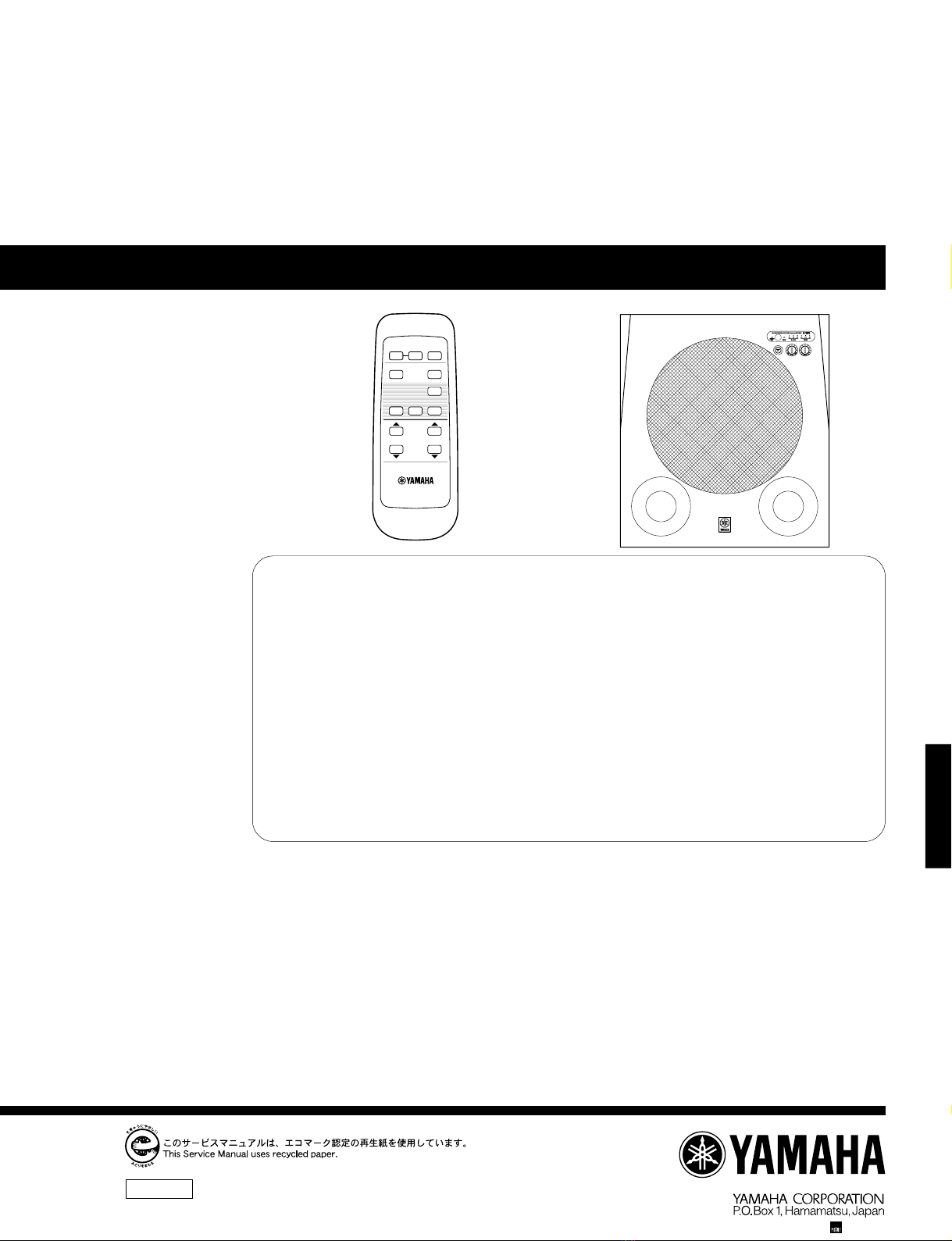
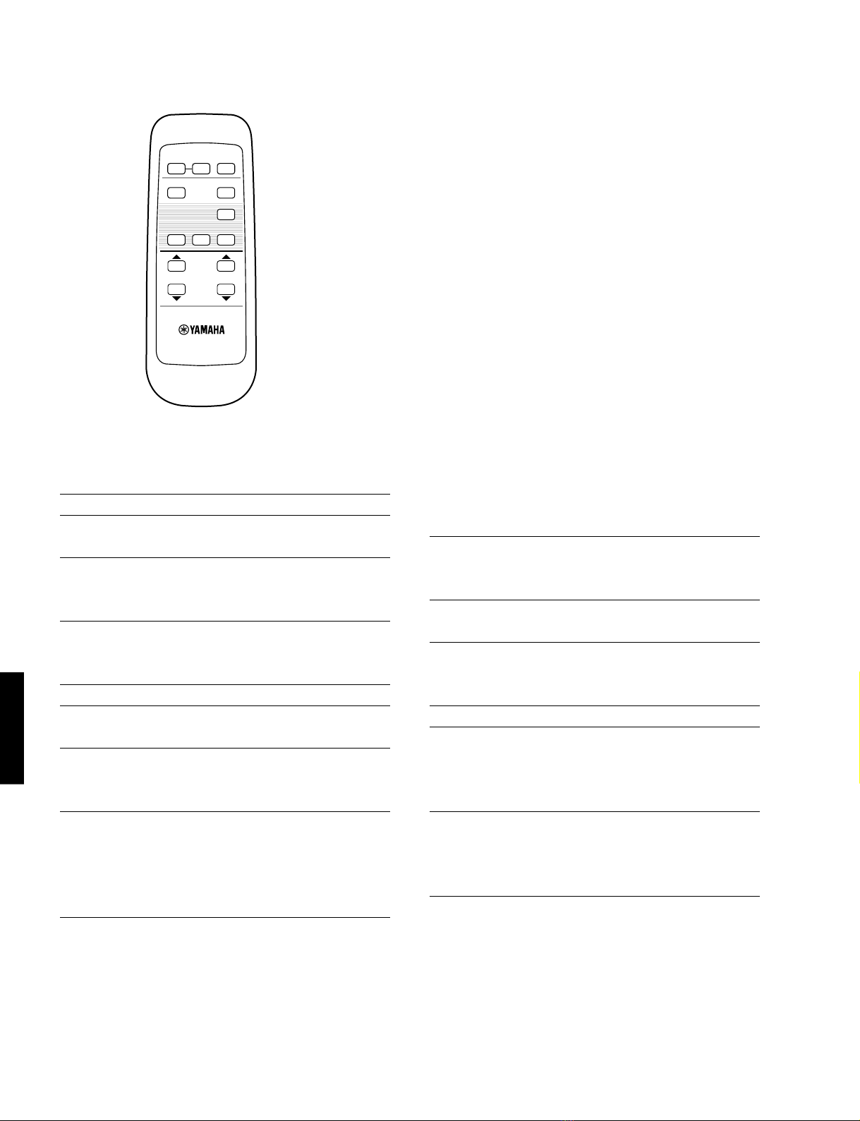
■REMOTE CONTROL PANEL
POWER
STANDBY
SLEEP
PHASE
MEMORY
PRESET
HIGH CUT VOLUME
231
B.A.S.S.
WH64300
Type / AdvancedYamaha Active ServoTechnology
II
Output Power /
100 Hz, 4 ohms, 10 % T.H.D ............................. 600 W
Input Sensitivity / (50 Hz, 600 W/4 ohms, L+R)
INPUT (SP) .......................................................... 1.2 V
INPUT (PJ) ......................................................... 70 mV
Input Impedance /
INPUT (SP) .................................................2.2 k-ohms
INPUT (PJ) ...................................................12 k-ohms
Frequency Response / 18 Hz to 160 Hz
Driver / 25 cm (10”) cone woofer
Magnetic shielding type
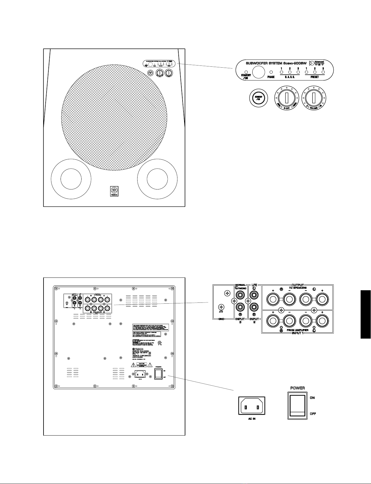
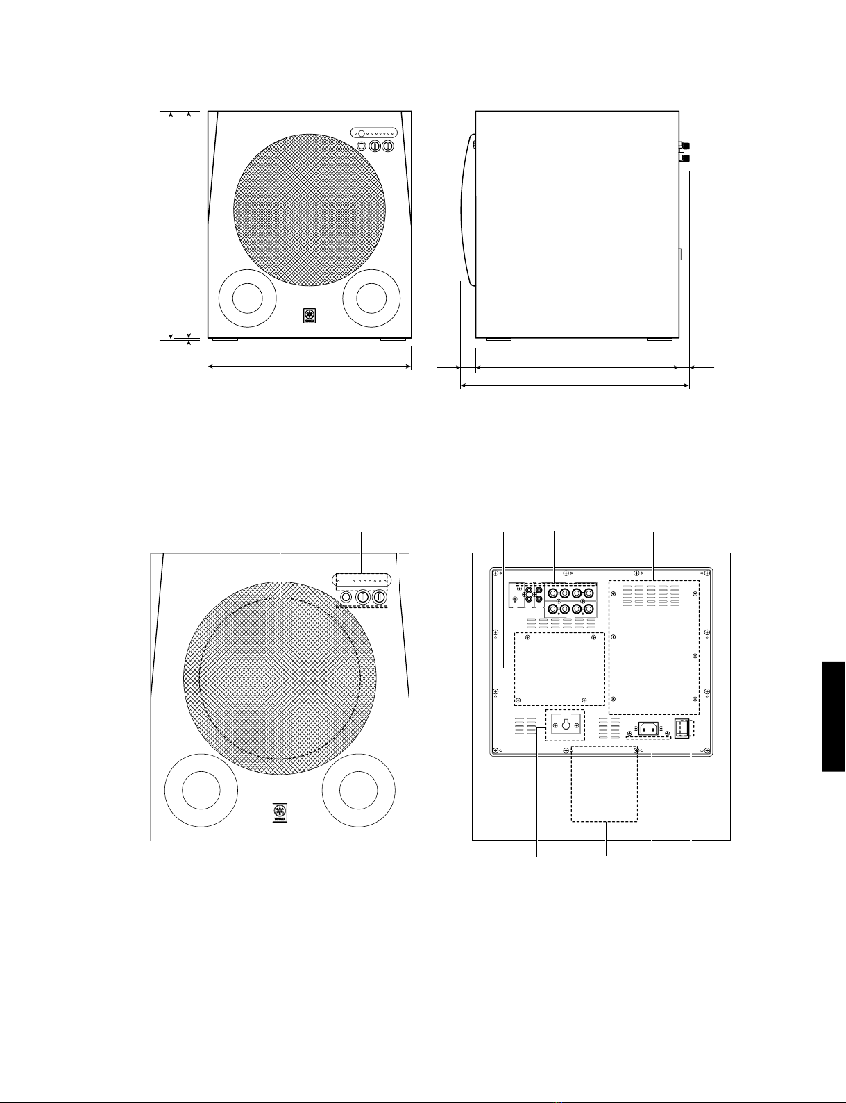
Input Section /
INPUT 1............................................. Speaker terminal
INPUT 2, 3................................................ RCA pin jack
Operation Section /
Top Panel.......... STANDBY/ON switch,Volume control,
H-CUT control, LED indicator
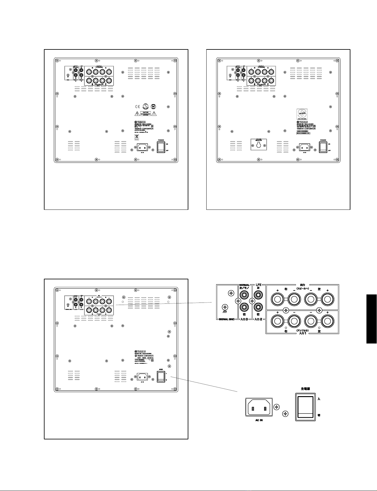
Rear Panel...............................................Power switch,
Voltage selector (R, L models)
Power Supply /
U, C models.........................................AC 120V, 60 Hz
R, L models .... AC 110, 120, 220, 230-240 V, 50/60 Hz
T model ...............................................AC 220V, 50 Hz
K model ...............................................AC 220V, 60 Hz
A model ...............................................AC 240V, 50 Hz
B, G models.........................................AC 230 V, 50 Hz
J model...........................................AC 100V, 50/60 Hz
Power Consumption /
U, C, R, T, K, A, B, G, L models.......................... 180 W
J model............................................................... 120 W
Standby Power Consumption /
..................................................0.5 W (reference data)
Dimensions (W x H x D) /
.................................... 410 mm x 461 mm x 461.5 mm
(16-1/8”x 18-3/16”x 18-3/16”)
Weight / ...................................... 32 kg (70 lbs.9 oz.)
Finish / Birch color (MN)
Brown color (MB)
Dark brown color (MD)
Black color (BL)
Accessories / ............................... Power cable x1,
Remote control x1, Battery x2,
Speaker cable (4 m) x1 (J model),
Subwoofer cable (5 m) x1 (J model)
* Specifications subject to change without notice.
U ....... USA model
C ....... Canadian model
R ....... General model
T ....... Chinese model
K ....... Korean model
A ....... Australian model
B ....... British model
G ....... European model
L ....... Singapore model
J ....... Japanese model

7
Soavo-900SW
Soavo-900SW
■DIMENSIONS
Unit : mm (inch)
410 (16-1/8")
461 (18-3/16")
457 (18")
410 (16-1/8")
4
(3/16")
30
(1-3/16") 21.5
(7/8")
461.5 (18-3/16")
■INTERNAL VIEW
qDRIVER
wMAIN (4) P.C.B.
eMAIN (3) P.C.B.
eq wrty
uio !0
rDIGITAL P.C.B.
tMAIN (2) P.C.B.
yMAIN (1) P.C.B.
uMAIN (7) P.C.B.(R, L models)
iPOWER TRANSFORMER
oMAIN (6) P.C.B.
!0 MAIN (5) P.C.B.

8
Soavo-900SW
Soavo-900SW
■DISASSEMBLY PROCEDURES/分解手順
(Remove parts in the order as numbered.)
Disconnect the power cable from the AC outlet.
1. Removal of Front Grille Ass'y
* The front grille ass'y is fixed to the cabinet with dowels
at 5 locations.
As a flatblade screwdriver is used for removal, use
special care not to cause damage to the cabinet ass'y.
a. Using the flatblade screwdriver inserted in the gap
between the front grille ass'y and the cabinet ass'y
(bottom side first), push up the front grille ass'y.
(Fig. 1)
b. Remove the front grille ass'y by lifting a metalblade
up. (Fig. 1)
* When installing the front grille ass'y, apply quick-drying
bond or the like to dowels and then fit them into dowel
holes for secure installation. (The front grille ass'y will
come off easily if its dowels are fitted into dowel holes
without applying quickdrying bond or the like.)
1.フロントグリルASS'Y の外し方
a. 底側からマイナスドライバー等を差し込みフロントグリ
ルASS'Y を押し上げます。(Fig.1)
b. 徐々にへら等で押し上げて、フロントグリルASS'Yを取
り外します。(Fig.1)
Fig. 1
Front Grille Ass'y
Driver
q
Flatblade Screwdriver
Dowels
Metalblade
Dowels
Cabinet Ass'y

9
Soavo-900SW
Soavo-900SW
2. スピーカーユニットの外し方
a. qのネジ8本を外し、スピーカーユニットを取り外し
ます。(Fig.1)
b.スピーカーユニットの端子からコネクターを外します。
(Fig.1)
3. リアパネル ASS'Yの外し方
a. wのネジ12本を外し、リアパネルASS'Yを取り外しま
す。(Fig.2)
b. CB4,CB5,CB15-17,CB20,CB22 を外します。(Fig.3)
2. Removal of Driver
a. Remove 8 screws (q) and then remove the driver.
(Fig. 1)
* Use an allen wrench (4mm) to unscrew the driver.
b. Disconnect the connector connected to the terminal of
the driver. (Fig. 1)
3. Remove of Rear Panel Ass’y
a. Remove 12 screws (w) and then remove the rea
panel ass’y. (Fig. 2)
* Arrow marks ( ) are printed to identify the screws to
be removed.
* When assembling the rear panel ass’y, check to ensure
that packing is not damaged so as to prevent air leakage
from occurring.
b. Remove CB4, CB5, CB15 (U, C, T, K, A, B, G
models), CB16-17, CB20 and CB22. (Fig. 3)
c. Remove CB13 and CB14. (R, L models) (Fig. 3)
Fig. 2
Fig. 3
w
Rear Panel Ass'y
CB20
CB5
CB16
CB17
CB15
CB14 CB13
CB4 CB22 MAIN (2)MAIN (1) DIGITAL
MAIN (5) MAIN (6) MAIN (7)
(R, L models)
(U, C, T, K, A. B, G, J models)

10
Soavo-900SW
Soavo-900SW
4. フロントパネル ASS'Yの外し方
eのネジ4 本を外し、フロントパネルASS'Yを取り外
します。(Fig.4)
5. 電源トランスの外し方
rのネジ 4 本を外し、電源トランスを取り外します。
(Fig.4)
P.C.B.チェックをする場合には
・リアパネルにある電源コード接続部を持ち上げるため
に、リアパネルASS'Yの下に枕木を敷いてください。
・分解の際に外したコネクターをすべて元通りに接続し
ます。
4. Removal of Front Panel Ass’y
Remove 4 screws (e) and then remove the front
panel ass’y. (Fig. 4)
5. Removal of Power Transformer
Remove 4 screws (r) and then remove the power
transformer. (Fig. 4)
When Checking the P.C.B.
•To help lift the power cable connecting section of the
rear panel, put the supporting wood under the rear
panel assembly.
•Connect all the connectors removed during
disassembly back to the original positions.
Fig. 5
Supporting Wood
Fig. 4
r
e
Power Transformer
Front Panel Ass'y

11
Soavo-900SW
Soavo-900SW
■REPAIR PROCEDURES/修理手順
Safety Measures
•Some internal parts in this product contain high voltages
and are dangerous. Be sure to take safety measures
during servicing, such as wearing insulating gloves.
•C77 and C80 on the MAIN (1) P.C.B. are dangerous,
for a high voltage is retained there even after the power
is turned off.
Before the repair work, connect about 5k-ohm/10W
resistor between terminals of the capacitor to forced
discharging.
After the repair work, also perform forced discharging
by connecting about 5k-ohm/10W resistor between
terminals of the capacitor.
Replacing Faulty Parts
Described below is the method to diagnose trouble of the
major parts.
FET (Q108, 109, 110, 111)
If a trouble exists, the D-S resistance value should be
close to 0-ohm.
(The normal value should be 1k-ohm or more.)
安全対策
・この製品の内部には高電圧部分があり危険です。修理の
際は、絶縁性の手袋を使用するなどの安全対策を行って
ください。
・MAIN(1)P.C.B. のC77およびC80 には電源 OFF 後も高
電圧が維持されるため危険です。
修理前に5kΩ/10W程度の抵抗をコンデンサの端子間に
接続して強制放電してください。
また、修理後も同様に5kΩ/10W程度の抵抗をコンデン
サの端子間に接続して強制放電してください。
故障部品を交換する
主な部品の故障判定方法を下記に示します。
FET(Q108,109,110,111)
故障している場合、D-S 間抵抗値は 0 Ωに近い値を示しま
す。
(正常値は 1k Ω以上を示します。)
GDS
D
S
D
S
D
S
D
S
DIGITAL P.C.B. (side A)
112
13
24
18
9
16
18
9
16
1
8
54

12
Soavo-900SW
Soavo-900SW
●Operation Check
Caution: When taking measurement at the following points
for operation check, do not use a voltmeter or the like which
may cause a failure.
●動作確認
必要なツール
DC 電圧計
信号発生器(100Hz,正弦波)
4Ω負荷抵抗
オシロスコープ
Required Tools
•Voltmeter
•Signal generator (100Hz, Sine wave)
•4-ohm load resistor
•Oscilloscope
13
24
18
9
16
18
9
16
54
Pin 10
Pin 14 Pin 10
Pin 14
DIGITAL P.C.B. (side A)
DIGITAL P.C.B. (side B)
Pin 10 of IC102
Pin 14 of IC102
Pin 10 of IC103
Pin 14 of IC103
Gate of Q108
Gate of Q109
Gate of Q110
Gate of Q111
Base of Q125
Emitter of Q125
Base of Q126
Emitter of Q126
Base of Q127
Emitter of Q127
Base of Q128
Emitter of Q128
D115—118
R166—169

13
Soavo-900SW
Soavo-900SW
1. 出力電圧の確認
a. MAIN(1)P.C.B.のCB22を外し、無負荷にします。
b. 本機の電源コードをAC コンセントに接続します。
c. 本機主電源入/切キーを入にして、STANDBY/
ONキーを押します。
d. SP +と GND 間および SP −と GND 間の DC 電圧を測定
します。
+50V ±5V
+50V ±5V
1. Output Voltage Check
a. Disconnect CB22 of the MAIN (1) P.C.B. so that no
load is applied.
b. Connect the power cable of this unit to the AC outlet.
c. Set the “POWER ON/OFF”key of this unit to the “ON”
position and press the “STANDBY/ON”key.
d. Measure the DC voltage between SP+ and GND and
also between SP–and GND.
Normal value
between SP+ and GND: +50V ±5V
between SP–and GND: +50V ±5V
e. 本機の主電源入/ 切キーを切にして、電源コー
ドを AC コンセントから抜きます。
2. 出力波形の確認
a. 信号発生器の出力信号を INPUT3L/MONOに接続しま
す。
b. スピーカーユニットに接続されているコネクタ端子を外
し、4Ω負荷抵抗に接続します。
c. 信号発生器の電源を入れ、正弦波・100Hz・出力レベル
最小に設定します。
e. Set the “POWER ON/OFF”key of the main unit to the
“OFF”position and disconnect the power cable from
the AC outlet.
2. Output Waveform Check
a. Connect the output signal from the signal generator to
INPUT 3 L/MONO.
b. Disconnect the connector connected to the speaker
unit and connect it to the 4-ohm load resistor.
c. Turn on the power of the signal generator and set for
the sine wave, 100Hz and output level minimum.
SP–
SP+
GND
MAIN (1) P.C.B. (side A)
SP+
SP–
GND

14
Soavo-900SW
Soavo-900SW
■DC OFFSET ADJUSTMENT/DCオフセット調整
d. 本機の電源コードをAC コンセントに接続します。
e.主電源入/切キーをONにして、STANDBY/ONキー
を押します。
f. SP+とSP−間の出力波形をオシロスコープで測定しま
す。
g. 信号発生器の出力レベルおよびSoavo-900SWのボリュー
ムを徐々に上げて、オシロスコープで出力波形を測定し
ます。
h. 出力レベル50Vp-p まで出力波形が歪まなければ、正常
と判断します。
i. 本機の主電源入/ 切キーを切にして、電源コー
ドをACコンセントから抜きます。
d. Connect the power cable of this unit to the AC outlet.
e. Set the “POWER ON/OFF”key to the ON position and
press the “STANDBY/ON”key.
f. Using the oscilloscope, measure the output waveform
between SP+ and SP–.
g. Increase the output level of the signal generator and
Soavo-900SW volume gradually and measure the
output waveform using the oscilloscope.
h. If the output waveform is not distorted until the output
level reaches 50Vp-p, it is judged as normal.
i. Set the “POWER ON/OFF”key to the “OFF”position
and disconnect the power cable from the AC outlet.
Precaution for handling measuring instrument
As the speaker output is B.T.L. connected, it is necessary
to make the ground side of the measuring instrument to
be connected to the speaker terminal loose.
Condition
•Start adjustment 5 sec or more after the power is
turned on.
•No input signal.
•Non loaded condition
DC offset adjustment
Adjust the potentiometer (VR101) on the DIGITAL P.C.B.
so that the DC voltage becomes 0 ±80 mV at speaker
output CB22 on the MAIN (1) P.C.B..
計測器取り扱い上の注意
スピーカー出力はB.T.L.接続となっていますのでスピー
カー端子に接続する計測器のアース側は、フローティング
が必要です。
条件
・電源を入れてから 5 秒間以上経過後に調整を始めます。
・無入力信号
・無負荷
DC オフセット調整
スピーカー出力端子(MAIN(1)P.C.B. のCB22)のDC電圧
が0±80mV になるように、半固定VR(DIGITALP.C.B.
のVR101)を調整します。
MAIN (1) P.C.B. (side A)
112
13
24
18
9
16
18
9
16
1
8
54
VR101
0 ±80 mV
DIGITAL P.C.B. (side A)

15
Soavo-900SW
Soavo-900SW
DIGITAL P.C.B.
VR101
0 ±80 mV
MAIN (1) P.C.B.

16
Soavo-900SW
Soavo-900SW
■IC DATA
PF3/INTPF2/SCK
RES
PA0/AD0
27
PA3/AD3
30
Port A
I. DEC
PC
STACK 1
STACK 8
ROM
1
PG0/AD4
1
PG3/AD7
4
Port G
PC0
17
PC3
20
Port C
PD0
21
PD3
24
Port D
I/O Bus
I/O Buffer
E
Port E
PF1/SO
14
Serial
Shift
Register
Serial
Mode
Register
AC ALU
DP
Serial
Mode
Register
RAM
PF0/SI
13
PF2/SCK
15
PF3/INT
16
Serial
Shift
Register
Lower Digit
Higher Digit
4 bit
4/8 bit
4/8 bit
AV+
5
AV-
6
8 bit
ADC
OSC1
8
RES
11
TEST
12
VDD
10
VSS
7
OSC2
9
25
PE0
26
PE1
Port F
13
PF0
16
PF3
26
WDR
System Bus
IR
STS
ZF
ZSF
CF TMF
EXTF
CSF
WRF
CTLTM
INT
OSC
PG0/AD4
PG1/AD5
PG2/AD6
PG3/AD7
AV+
AV-
VSS
OSC1
OSC2
VDD
TEST
PF0/SI
PF1/SO
1
2
3
4
5
6
7
8
9
10
11
12
13
14
15
30
29
28
27
26
25
24
23
22
21
20
19
18
17
16
PA3/AD3
PA2/AD2
PA1/AD1
PA0/AD0
PE1/WDR
PE0
PD3
PD2
PD1
PD0
PC3
PC2
PC1
PC0
IC7 : LC651152N-4N21-E (MAIN (1) P.C.B.)
8-bit Microprocessor
1
2
3
4
5
6
7
8
9
10
11
12
13
14
15
16
17
18
19
20
21
22
23
24
25
26
27
28
29
30
PG0/AD4
PG1/AD5
PG2/AD6
PG3/AD7
AV+
AV-
VSS
OSC1
OSC2
VDD
RES
TEST
PF0/SI
PF1/SO
PF2/SCK
PF3/INT
PC0
PC1
PC2
PC3
PD0
PD1
PD2
PD3
PE0
PE1/WDR
PA0/AD0
PA1/AD1
PA2/AD2
PA3/AD3
Standby LED driving output, GREEN
Standby LED driving output, RED
Predicted danger detection
STANDBY/ON SW detection
Reference voltage for AD conversion
Connection for grounding
Clock
Clock
Power supply +5V
System reset input
Connection for grounding
Preset 1 LED driving output
Preset 2 LED driving output
Preset 3 LED driving output
Remote control signal detection
Power supply relay driving output
Speaker relay output
Low cut filter control A
Low cut filter control B
Motor 1 clockwise revolution
Motor 1 counterclockwise revolution
Motor 2 clockwise revolution
Motor 2 counterclockwise revolution
Phase LED driving output
Error detect terminal
Motor 1 angle detection
Motor 2 angle detection
Danger preview input check pulse output
Standby terminal
No.
Port Name
Function
OUT
OUT
A/D
IN
POWER
GND
GND
CLK
CLK
POWER
IN
GND
OUT
OUT
OUT
IN
OUT
OUT
OUT
OUT
OUT
OUT
OUT
OUT
OUT
IN
A/D
A/D
OUT
IN
I/O

ABCDEFGH
1
2
3
4
5
6
Soavo-900SW
17
■BLOCK DIAGRAM
See page 21 SCHEMATIC DIAGRAM
See page 22 SCHEMATIC DIAGRAM
XL101
DRIVER
WOOFER
AC IN
XL1
STANDBY/ON
Q6
+
-
-
INPUT1
L
R
OUTPUT
R
L-
-
+
+
+
6
57
-
+2
3
1
3
2
2
-
+
L.P.F.
6dB/oct
5
6
7
-
+
L.P.F.
12dB/oct
4
3
2
-
+
L.P.F.
12dB/oct 4
3
IC2A
IC1A
IC1B
IC2B
6
7
8
-
+
L.P.F.
12dB/oct
1
IC3A IC3B
-
+
MVR2
H-CUT
VR2
MOTOR DRIVER
IC6
POSITION
SEARCH
IC4A
6
7
8
-
+
H.P.F.
12dB/oct
6
42
-
+
H.P.F.
12dB/oct
IC4B IC5A
H.P.F
SELECTOR
8
L.P.F.
6dB/oct
IC5B
IC8
POSITION
SEARCH
M
MOTOR
DRIVER
37
VR2 VR1
VR1
VOLUME PHASE
SELECT
RY3 3
4
2
+
--
+
IC12A
7
6
8
-
+
L.P.F.
6dB/oct
IC12B
INPUT3
INPUT2
(LFE)
PJ1
PJ2
TE1
MODULATOR
CLOCK 2MHz
DRIVER
DRIVER
MOSFET
Q108
MOSFET
Q109
MOSFET
Q110
MOSFET
Q111
L.P.F
L101
C153
L.P.F
L101
C153
FILTER
FILTER
IC109
IC103
IC102
IC101
FEEDBACK
FILTER
L112
IC110
IC111
REGULATOR
+15D
-15D
+5
-5
PROTECTION
Q116,117,121
A.N.I.C
IC13,14,Q20-22
RY1
+
–
IC17
IC18
REGULATOR
+15D
-15D
+15
-15
POWER
SUPPLY
D27
POWER TRANSFORMER
POWER ON/OFF
SW1
L4
RY2
F1
IC15
IC16
REGULATOR
DRIVER
Q14,15
DRIVER
DRIVER
Q19
Q7
D38
POWER
SUPPLY
T2
REGULATOR
IC11
+5
RESET
CIRCUIT
+B
POWER
SUPPLY
POWER
SUPPLY
D37
DIGITAL
P.C.B.
11 RES
17 PWRY
18 SPRY
26 ERR
25 PH
21,22 M1R,M1F
27 M1A
19,20 HPCA,HPCB
23,24 M2R,M2F
28 M2A
MICROPROCESSOR
IC7
RMT 16
REMOTE
CONTROL
SENSOR
U1
PWS 4
M1L,M2L,M3L 13,14,15
PWG,PWR 1, 2
SW4
IC9
LED
SELECT
IC10
STANDBY/ON, PHASE, B.A.S.S. 1,2,3
PRESET 1,2,3
D5-9,11-13
-
+
PROTECTION
3 DTC
Q16
CLOCK 2MHz
8,9
DIGITAL
MAIN
L/MONO
R
L
R

ABCDEFGH
1
2
3
4
5
6
Soavo-900SW
18
■PRINTED CIRCUIT BOARDS
MAIN (1) P.C.B. (Side A) MAIN (2) P.C.B. (Side A)
MAIN (3)
CB6
MAIN (5)
W3
POWER TRANSFORMER
MAIN (3)
CB21
MAIN (3) CB3
DIGITAL
CB101
DIGITAL
CB105
DIGITAL
CB106
MAIN (6)
W5B, W6B
DRIVER
WOOFER
POWER TRANSFORMER
(U, C,T, K, A, B, G, J models) POWER TRANSFORMER
(R, L models)
LR
OUTPUT
INPUT 1
1
9
1
9
1
9
1
15
30
16
1
2
CH1
2
CH2
18 18
5 k-ohms
10W
L3
INPUT 2 (LFE)
L/R INPUT 3
L/MONO /R
Circuit No.
CB11
CB19
R120
C62
R107
D31
Q17,18
R117
C65
C66
CB15
W8, 9
G1
C149, 150
J
X
O
X
X
X
X
X
O
X
O
O
X
O
O
X: NOT USED
O: USED/APPLICABLE
U, C
X
O
X
X
X
X
X
O
X
O
O
X
O
O
R, L
X
O
O
O
O
O
O
X
O
X
X
O
X
X
T, K
O
X
X
X
X
X
X
O
X
O
O
X
O
O
A
O
X
X
X
X
X
X
O
X
O
O
X
O
O
B,G
O
X
X
X
X
X
X
O
X
O
O
X
O
O
MAIN (1)
Point w
CH 1 : Out of IC11
CH 2 : Pin 11 of IC7
↑
AC POWER ON
(Connect the power cable)
↑
AC POWER OFF
(Disconnect the power cable)
↑
AC POWER ON
(Connect the power cable)
Point q(Pin 8 of IC7)
安全対策
・この製品の内部には高電圧部分があり危険です。修理の際は、絶縁性の手袋を使用するなどの安全対策を行ってください。
・MAIN(1)P.C.B. のC77 およびC80 には電源 OFF 後も高電圧が維持されるため危険です。
修理前に 5k Ω /10W程度の抵抗をコンデンサの端子間に接続して強制放電してください。
また、修理後も同様に 5k Ω /10W程度の抵抗をコンデンサの端子間に接続して強制放電してください。
Safety Measures
•Some internal parts in this product contain high voltages and are dangerous. Be sure to take safety measures during servicing, such
as wearing insulating gloves.
•C77 and C80 on the MAIN (1) P.C.B. are dangerous, for a high voltage is retained there even after the power is turned off.
Before the repair work, connect about 5k-ohm/10W resistor between terminals of the capacitor to forced discharging.
After the repair work, also perform forced discharging by connecting about 5k-ohm/10W resistor between terminals of the capacitor.

ABCDEFGH
1
2
3
4
5
6
Soavo-900SW
19
MAIN (1)
CB20
MAIN (1)
CB5
MAIN (1)
CB4
STANDBY
/ON
PHASE
12
B.A.S.S.
312
PRESET
3
STANDBY
/ON H-CUT VOLUME
19
19
19
110
110
18
169
18
169
M+
M+
POWER
ON/OFF
MAIN (1)
CB23
POWER TRANSFORMER
MAIN (1)
W8A, W9A
VOLTAGE SELECTOR
240V
220V
110V
120V
1−2/5−6
2−3/6−7
3−4/7−8
4−5/8−1
SW2
POWER TRANSFORMER
AC IN
MAIN (1)
W5A, W6A
MAIN (7) P.C.B. (Side A)
MAIN (6) P.C.B. (Side A)
MAIN (5) P.C.B. (Side A)
MAIN (3) P.C.B. (Side A) MAIN (4) P.C.B. (Side A)
R, L models

ABCDEFGH
1
2
3
4
5
6
Soavo-900SW
20
DIGITAL P.C.B. (Side A) DIGITAL P.C.B. (Side B)
MAIN (1) W10
MAIN (1) W11 MAIN (1) W12
3
112
13
24
18
9
16
18
9
16
1
8
54
DC OFFSET ADJUSTMENT
Point e(Pin 23 of IC101)
Caution: When taking measurement at the following points for
operation check, do not use a voltmeter or the like
which may cause a failure.
Pin 10 of IC102
Pin 14 of IC102
Pin 10 of IC103
Pin 14 of IC103
Gate of Q108
Gate of Q109
Gate of Q110
Gate of Q111
Base of Q125
Emitter of Q125
Base of Q126
Emitter of Q126
Base of Q127
Emitter of Q127
Base of Q128
Emitter of Q128
D115—118
R166—169
Table of contents
Other Yamaha Subwoofer manuals

Yamaha
Yamaha SW10 STUDIO User manual

Yamaha
Yamaha NS-SW210 User manual

Yamaha
Yamaha NS-SW901 User manual

Yamaha
Yamaha NS-SW500 User manual

Yamaha
Yamaha IS1215 User manual

Yamaha
Yamaha NS-SW210 User manual

Yamaha
Yamaha NS-SW300 User manual

Yamaha
Yamaha SW-3 User manual

Yamaha
Yamaha YST-SW216 User manual

Yamaha
Yamaha YST-SW105 User manual

Yamaha
Yamaha YST-SW120 User manual

Yamaha
Yamaha NS-SW310 User manual

Yamaha
Yamaha YST-SW012 User manual

Yamaha
Yamaha YST-SW100 User manual

Yamaha
Yamaha YST-SW005 User manual

Yamaha
Yamaha DXS18 User manual

Yamaha
Yamaha YST-SW515 User manual

Yamaha
Yamaha YST-SW45 User manual

Yamaha
Yamaha IS1112(W) User manual

Yamaha
Yamaha YST-SW300 User manual