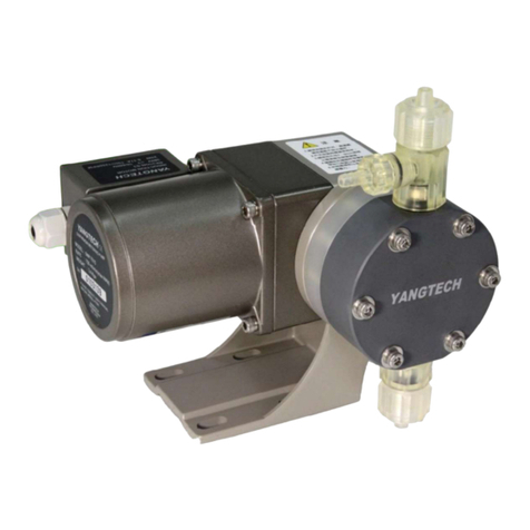
YANGTECH EMP Series User manual

A05G069A
1
YANGTECH
(ENGLISH 2106)
EMP-Series Multifunctional Electromagnetic
Metering Pump
EMP-3706/4210/5320
IP65
YANGTECH TECHNOLOGY CO., LTD.
(Taiwan)
O P E R A T I O N M A N U A L

A05G069A
2
YANGTECH
EMP- Multifunctional Electromagnetic Metering Pump
EMP-3706/4210/5320
Installation and Maintenance Manual
1. FEATURES
Thank you for your purchase of this product. EMP-series metering pump has following
outstanding characteristics. They can be widely applied in various types of auto-dosing
procedure.
◼CE standard certified.
◼Production qualities are ISO9001certified.
◼All PPO plastic outer casing. Excellent crossion resistance.
◼IP65 standard certified. Waterproof and dustproof
◼Multi-functional display of LED. High identification in dark places.
◼Informations of Pulse rate/Rate percentage/Flow rate/Batch count can be displaied.
◼Solenoid directly drive design. Only 25 Watts of power consumption.
◼Power range of 100V~240Vcan be applied which is more convenient.
◼Standardly equip with panel cover.
◼Standardly equip with level sensor junction. Pump stop automaticlly when fluid level is
low.
◼Standardly equip with solenoid coil temperature sensor.
◼Stroke-length and pulse-rate are both adjustable.Precision flow control can be achieved.
◼Double check valve design both in inlet and outlet joints. Flow rate is more stable.
◼Rotary pump base which makes more convenient when installing.
◼Function of receiving 4~20mA or 0~10V industrial standard analog signal.(Optional)
◼Function of receiving volatge -pulse/on-off signal.(Optional)
◼Batch function of pulse and time(in second)count down. (Optional)
◼Equiped with 5V,500mA power supply connection. (Optional)
◼Equiped with external run/stop and max-rate switchs connections. (Optional)
2. NOTICES
Not in accordance with the manual may cause
malfunction of pump or even injury of operator !
⚫Read this manual thoroughly before installation and operation.
⚫Install this pump in a place of ventilation(environmental temp. between 5~40℃).
Keep away from high temperature / high humidity / corrosive gases.
⚫Outdoor installation must give a shelter, this can effectively increase the pump`s life.
⚫This product is not explosion-proof rating, do not install in a place of potentially
gas/dust explosion.
⚫The signal line (especially the analog 4-20mA or 0-10V) cannot be configured in
parallel with the power line. The pump position should be more than 1 meter away
from the transformer, inverter, and induction motor to avoid interference.
⚫For models with I/O cables, except for the contact cables that need to be used, other

A05G069A
3
unused wires must be cut off or covered the metal ends.
⚫Do not use a inverter as power supply. This cause damage of this product.
⚫Must drain the pipe before installation. Install pump to a pressured pipe is
extremely high dangerous. It may cause a serious injure of operator.
⚫Do not operate the pump in a pressure higher than specification , or fluid viscosity
>500 cP or temperature >60℃.
⚫This unit is not suitable for all kind of fluid. Some solvents, extreme acid, high
oxidization high temperature or high viscosity fluid may cause malfunction of pump.
⚫Wear a chemical protect mask and gloves before repair or maintenance.
⚫Please do not try to modify the pump or use non-original parts. This damage pump
and cause warranty become invalid.
Scheme 1 System configuration diagram (Example)
1. Level sensor
2. Check valve/filter
3. Pump
4. Release valve
5. Pressure gauge
6. Back pressure valve
7. Analog controller
8. Analog sensor
9. Target chemical tank
10. Pipe injector
11. Source chemical tank
12. Pulse damper
13. Flow sensor
14. Digital/analog flow
controller
15. Drain valve pipe
16. Anit-siphon valve
NOTICE:
Not all of these devices
are installed. In most
case only part of the
components will be
installed.
100~240V
AC
OR

A05G069A
4
⚫Notices of piping (Piping configuration consult scheme 1):
1. If pump location is above chemical container, do not excess 2.0meters higher
than the chemical lowest level in the container and check valve must be installed
vertically. High suction head may lead fail inhalation. Permissible suction head
is affected by Liquid viscosity, specific gravity, pipeline conditions.(We do not
guarantee suction head of this product)
2. When input hose is empty, pump may not able to suck liquid into pump
head automatically. In this case you can try to full the hose with liquid
then raise it up higher than pump head and start pumping. This procedure
may solve suction problem. (If a pipe injector will be install, install it after
pump can pump out normally. )
3. The pressure loss cause by pump pulse should below 1.0 Kgf/cm2 ,otherwise the
pipe start to vibrate. In this case, a pulse reducer can be installed or reduce
piping length/elbow or increase pipe diameter.
4. Be aware that pressure discrepancy between input output hose should higher
than the inner pressure loss of this pump otherwise, overfeeding even siphon
phenomenon may occur. In this case an anti-siphon/backpressure valve(both are
optional) should be installed.
5. Fluid which is easy to gasify or vaporize (Ex. H2O2, most solvents). Gas in pump
head cause variation of flow rate. In this case purge the gas through drain
valve.
6. Output pipe may install following devices to solve some problems:
Pulse damper -To reduce pipe vibration especially pipe is long/thin/plenty of
elbows
Pressure gauge -To monitor output pipe pressure.
Release valve -To prevent pipe from rupture cause by exceptional high
pressure and secure operator against hazard.
Back-pressure -To keep constant pressure of output pipe and improve flow
valve rate stability.
Pipe injector -To connect hose/pipe to other pipe.
Anti-siphon - If pumping destination altitude is lower than source
Valve tank siphon phenomenon occur. In this case an anti-siphon
valve should be installed.

A05G069A
5
3. INSTALLATION
⚫This product is suitable for universal power source(100V~240V AC/φ1/ 25Watts
RMS), but installer still need to confirm that the power source is in the range.
⚫Make sure this pump is horizontally installed.
⚫Pump base dimensions illustrate below:
1. 4 long-shape holes for M5-25 fixing
screw
2. 2 oblique-shape holes for M4、
M5、M6 fixing screw
3. Standard accessories:SUS304
M5-25 Socket head cap screw
*2+M5 nut*2+M5 plate washer*4
⚫This pump equip with 2 meters length 5-cores cable (standard) and 13-cores
cable(multifunctional model only). Use a junction box(optional) connect them to
external power source/level sensor/signal/switches.
⚫Install this pump in a place of ventilation(environment temp, between 0~40℃). Keep
away from high temperature / high humidity / corrosive gases.
⚫If operate pump continuously at high pulse rate and long period of time, the
temperature of case may reach 60℃. If you touch with bare hand you feel very hot
but this is normal. Yet if operation condition cause over-temperature-protect-switch
(inside the pump) acts frequently. You should check power source/liquid
viscosity/environment temperature/ ventilation etc. to solve this problem.
⚫Fasten the pump on a horizontal and rigid base. This prevent pump from loosing or
falling and ensure safety of operator.
⚫After install the pump, connect to pump both inlet/outlet and check valve with
standard hoses. (1/4”PVC hose,I.D.φ6.0mm,O.D. φ11mm) Keep a distance of
about 25~30cm between check valve and tank bottom to prevent from suction of
precipitations.
⚫The inlet/outlet connectors are made of plastic, use bare hand to rotate and fasten
them. Do not try to fasten connectors with tools it may break the connectors.
⚫If pump into a pressured pipe/tank, a injector ( an optional accessory ) is needed .

A05G069A
6
4. MODEL IDENTIFICATION
EMP-42 10 - AC H-U AB
A B C D E F G
A= Series Code (Pump Series)
B= Diaphragm Diameter (40=φ40mm, 46=φ46mm, 53=φ53mm)
C= Flow Rate Code (06=60ml/min, 10=100ml/min, 20=200ml/min)
D= Material Code (Consult material code list below)
E= Joint Code (H=1/4”Hose Type , S=10mm Hose Type)
F= Power Code (U=Universal 100~240V,φ1 / 2=220V,φ1 / 1=110V,φ1)
G= Special Code (Null =Standard, A=Analog Fn. ,D=Digital Fn. ,B=Batch
Fn. ,T=Timer Fn.)
⚫MATERIAL CODE LIST:
Material Code
AC
AF
BS
VS
SS
Application
Common
Acid
Strong Oxidative
Acid
Common
Alkali
Thick
fluid
Solvent
1.Valve Ball
Ceramic
Ceramic
SUS316
SUS316
SUS316
2.Ball Seat
FKM
PTFE
EPDM
EPDM
PTFE
3.Pump Head
PVC
PTFE
PVC
PVC
SUS304
4.Diaphragm
PTFE + EPDM + SUS304 + Nylon Fiber
5.O-Ring
FKM
PTFE
EPDM
EPDM
PTFE
6.Gasket
FKM
PTFE
EPDM
EPDM
PTFE
Remark:PVC :Polyvinyl chloride
SUS304/316:Stainless Steel
Viton :Fluoro Rubber FKM
EPDM :Ethylene Propylene Rubber
PVDF :Polyvinylidene fluoride
Ceramic :Al2O3
PTFE :Polytetrafluoro Ethylene
Wet-End Structure

A05G069A
7
5. PACKING AND CONTENTS
⚫Packing Dimension:L260mm*W180mm*H253mm (Double layer corrugated paper carton)
⚫Standard Contents:
Item
CONTENTS
ACH
BSH
AFH
VSH
SSH
1.
Pump*1
S
S
S
S
S
2.
PVC Hose 1/4”(6* 11mm) *3.0m
S
S
-
-
-
3.
PVC Hose 3/8”(9.5* 15mm) *3.0m
-
-
-
S
-
4.
PTFE Hose 8*10mm*3.0m
-
-
O
-
O
5.
Screw Set (M5-25 *2+Gasket*4)*1
S
S
S
S
S
6.
Operation / Installing manual*1
S
S
S
S
S
7.
PTFE Connector 1/2”PT-8*10mm*1
-
-
S
-
-
8.
SUS304 Connector 1/2”-8*10mm*1
-
-
-
-
S
9.
PTFE Filter Check Valve (8*10mm) *1
-
-
O
-
O
10.
PVC Filter Check Valve 1/4”(6* 11mm) *1
S
S
-
-
-
11.
PVC Check Valve 3/8”(9.5* 15mm) *1
-
-
-
-
-
12.
PTFE Injector (8*10mm)*1
-
-
O
-
O
13.
PVC Injector 1/4”(6*11mm)*1
O
O
-
-
-
14.
PVC Injector 3/8”(9.5*15mm)*1
-
-
-
O
-
S : Standard O:Optional -: Not Available
(Check all the contents are correct when you receive package of your order.)

A05G069A
8
6. OPERATIONS
⚫PUMP COMPONENTS DESCRIPTION:
Hose cap Panel cover Purge valve
Outlet
connector
Operation
panel
Pump Stroke knob
head
Display
Pump
Inlet Signal I/O body
connector connector
Hose
cap Power/level
connector
Rotatable
base
FRONT SIGHT SEMI-BACK SIGHT
⚫PANEL DESCRIPTION:
SWITCHES AND KNOB:
Switch -RUN/STOP
When not in batch mode, toggle this switch to stop/run
pumping.
When in batch mod, toggle this switch to pause/resume
pumping, pressing longer than 5 seconds to abort
batching.
Switch -DISP.
When not in batch mode, press this switch to change LED
display within 3 unit3(Pause/min, ml/min, % of setting
range)
When not in batch mode, press this switch to change LED
display within in 4 units(Countdown in seconds,
Pause/min, ml/min, % of setting range)
Switch -MODE
Press over than 5 seconds to blink LED display then press
MODE to change operation mode from Mode1 to Mode9
(number of modes may very depend on the pump model)
When selected mode was displayed, press MODE over 5
seconds to enter target mode.(LED stop blinking)
Current Current
Mode Value

A05G069A
9
Switch -PROG. and ▲▼
Press over 5 seconds, LED display blinks and show Cd01,
press ▲▼to select proper code you like then press
PROG. again, blinking LED display shows value of this
code. Press ▲▼to select proper value then Press
PROG. again to save this value and back to show Cd01
again to continue other code setting.
(Anytime press PROG. over 5 seconds to back to display
mode)
Stroke adjust knob
You can adjust pump stroke from 0 to 10.(represent 0.0 to
1.0 mm of real stroke)
Graduator less than mark 5(real stroke length shorter than
0.5mm) the flow rate may become unstable , so avoid
running pump when graduator less than mark 5.
Stroke adjust knob
INDICATORS(LAMPS):
●Batch Fn.-sec (Batch function in second)
Green light on –The unit of LED display value
is ”second”.
●Batch Fn.-Pulse (Batch function in Pulse)
Green light on –The unit of LED display value
is ”pulse”.
●●Pwr./Run/Stby.(Power/Run/Standby)
Green light on - pump in stop mode and power is on.
Green light blink - blink frequency is the same with
pumping pulse.
Orange light is on –pump is in pause mode .(Some
procedure is running but is paused)
●Low Level
Red light on –the level in source chemical container is
low, pump stop when light is on.
●Pulse/min
Green light on - the unit of LED display value is ”
Pulse/min”.
●ml/min
Green light on - the unit of LED display value is ”
ml/min”.
●% of Range
Green light on - the unit of LED display value is ” %
of setting range”.(current pulse rate - min. set pulse rate)
Definition = (max. set pulse rate -min. set pulse rate)

A05G069A
10
⚫OPERATION MODE:
Mode
Code
Mode
Name
Descriptions
1.
General
Mode
The simplest(general) mode. When source power is on the
pump start to pumping. When source power is off the
pump stop synchronously.
This mode is suitable for manually operation or the pump
is controlled by a external controller.(pH/O.R.P./ Cl2 etc.)
RUN/STOP*:Toggle this switch to run / stop the pump.
DISP. :Press this switch to change the unit of LED
display. (Note1)
▲▼:Press to increase/decrease the pulse rate, run
in highest pulse rate immediately when
press both at the same time.
2.
External
4~20mA Mode
(Optional)
In this mode pumping pulse rate vary proportionally to the
external 4~20mA current signal.
This mode is suitable for proportionally dosing procedure.
Generally pump is controlled by a P.I.D. controller.
RUN/STOP*:Toggle this switch to run / stop the pump.
DISP. :Press this switch to change the unit of LED
display. (Note1)
▲▼:invalid.
3.
External
0~10V Mode
(Optional)
In this mode pumping pulse rate vary proportionally to the
external 0~10 voltage signal.
This mode is suitable for proportionally dosing procedure.
Generally pump is controlled by a P.I.D. controller.
RUN/STOP*:Toggle this switch to run /stop the pump.
DISP. :Press this switch to change the unit of LED
display. (Note1)
▲▼:invalid.
4.
External
Multiple
Mode
(Optional)
Pumping frequency is a integer multiples to the external
voltage/on-off pulse signal. (suitable for
PC/Encoder/Probe/PLC devices which generate pulse
signal to control the pump)
For example:The pump works 4 pulses when accept 1
signal.
external signal(1p)
pump action (4p)
RUN/STOP*:Toggle this switch to run / stop the pump.
DISP. :Press this switch to change the unit of LED
display. (Note1)
▲▼:invalid.

A05G069A
11
5.
External
Fractional
Mode
(Optional)
Pumping frequency is a integer fraction to the external
voltage/on-off pulse signal. (suitable for
PC/Encoder/Probe/PLC devices which generate pulse
signal to control the pump)
For example:The pump works 1 pulse when accept 6
signals.
RUN/STOP*:Toggle this switch to run / stop the pump.
DISP. :Press this switch to change the unit of LED
display. (Note1)
▲▼:invalid.
6.
External
Synchronous
Mode
(Optional)
Pumping frequency is synchronous to the external
voltage/on-off pulse signal. (suitable for
PC/Encoder/Probe/PLC devices which generate pulse
signal to control the pump)
For example:The pump work 1 pulse when accept 6
signals.
RUN/STOP*:Toggle this switch to run / stop the pump.
DISP. :Press this switch to change the unit of LED
display. (Note1)
▲▼:invalid.
7.
Batch in
Time Mode
(Optional)
Pumping is controlled by a time count-down(By second)
procedure(a batch).The count-down timing can be set in
code05.
Suitable for batch dosing procedure and which is more
convenient to execute in time count-down.
RUN/STOP*:Toggle this switch to run / pause the pump.
Press over 5 seconds to abort a running
batch immediately.
DISP. :Press this switch to change the unit of LED
display. (Note1)
▲▼:invalid.
External batch control box configuration. (Note2)
8.
Batch in
Pulse Mode
(Optional)
Pumping is controlled by a pulse count-down (By pulse)
procedure(a batch).The count-down pulses can be set in
code06.
Suitable for batch dosing procedure and which is more
convenient to execute in pulse count-down.
RUN/STOP*:Toggle this switch to run / pause the pump.
Press over 5 seconds to abort a running
batch immediately.
DISP. :Press this switch to change the unit of LED
display. (Note1)
▲▼:invalid.
External batch control box configuration. (Note2)
9.
Timer Mode
(Optional)
Pump on /off repeatedly in a procedure that running for a
period of time then stop for a period of time.
For example you can set pump running for 3600 seconds(1
hour) and stop for 60 seconds(1 minutes) alternatively.
RUN/STOP:Toggle this switch to run / pause the pump.
External signal(6)
Pump action(1)

A05G069A
12
Press over 5 seconds to abort a running
batch immediately.
DISP. :Press this switch to change the unit of LED
display. (Note1)
▲▼:invalid.
*:External RUN/STOP key switch, PLC/push-type switch/solid-state switch can be used,
general mechanical relay may not be suitable for excessive noise
(Note1):Display changing order diagram
In mode01~06 :
Press DISP. Press DISP.
Pulse rate(Pulse/min) % of range(%) Flow rate(ml/min)
Press DISP.
In mode07,08,09:
Press DISP. Press DISP. Press DISP.
Pulse/Time Pulse rate 式(Pulse/min) Flow rate (ml/min) % of range (%)
Press DISP.
(Note2):External batch control box configuration(Example)

A05G069A
13
⚫CODE DESCRIPTIONS:
CODE
CODE NAME
UNIT
DESCRIPTIONS
01
Lowest Stroke
Rate
p/m
Default=0,Variation=0-80
(In Mode 4,5,6 is invalid)
02
Lowest Stroke
Rate
p/m
Default=200,Variation=100-200
(In Mode 4,5,6 is invalid)
03
Dividing
-
Default=01,Variation=1-9999
04
Multiple
-
Default=01,Variation=1-9999
05
Batch Timer
sec
Default=9999,Variation=0-9999
1. Actually count-down timer = (cd05) * (cd07).
For example, if cd05=5000 and cd07=100
then count-down
timer=5000*100=500000(seconds)
2. If value excesses 4 digits, 1~3 decimal points
will blink to hint how many digits wasn`t
shown up.
06
Batch Pulses
Counts
Pulse
Default=9999,Variation=0-9999
1. This code is similar to code05.Actually
count-down pulses= (cd06) * (cd07). For
example, if cd06=5000 and cd07=100 then
count-down
pulses=5000*100=500000(pulses)
2. If value excess 4 digit, 1~3 decimal points
will blink to hint how many digits wasn`t
shown up.
07
Code5,6,9,A
multiple
-
Default=1,Variation=1,10,100,1000
Valid in mode7,8,9
08
Flow Rate
At 200 Hz.
ml/min
Default=100,Variation=1-9999
Calibration procedure:
1. After installed pump and check all pumping
conditions are ready.
2. Switch to mode1 and set pump rate up to 200
pulse/min.
3. Use stopwatch and graduated cylinder to
measure the volume of pumping for 1 minute.
4. Input the result to code08. This makes LED
unit display in ml/min accurately.
09
Mode9 Running
Time
sec
Default=60,Variation=1-9999
Set pump running period of mode9.
0A
Mode9 stopping
Time
sec
Default=60,Variation=1-9999
Set pump stopping period of mode9.

A05G069A
14
⚫CABLE AND CONTACTS SPECIFICATIONS:
Pin No.
Colors
Functions & Specs
Power/Level cable(5 cores,AWG18 /105℃/ 220VAC/1.0A,length 2.0 meters)
A1.
BLUE
External power line
A2.
WHITE
External power line
A3.
GREEN
External power line ground (No connect to power source)
A4.
RED
Level sensor/switch (No connect to power source)
A5.
RED/WHITE
Level sensor/switch (No connect to power source)
I/O cable (13cores,AWG26/105℃/60V DC/0.5A,length 2.0 meters)
B1.
RED
External voltage signal 0~10V
(Input resistance approx. 20KΩ)
B2.
ORANGE
External current signal 4~20mA
(Input resistance approx. 200Ω)
B3.
YELLOW
External pulse signal
1. voltage range =0~60V
2. No-voltage contact or open collector, input resistance
approx. 2kΩ
3. Max. number of pulses= 9000 pulse/min, min. pulse
width: 3.33 mSec (ON/OFF time) (Note1)
4. Volt< 0.8V = Low level,Volt= 3.0~ 60.0V = Hi level
B4.
BLACK
common
(for all signal of voltage/current/pulse/on-off)
B5.
GREEN/
WHITE
Power supply
Output 5.0 V, max.400mA (with 0.5A auto reset fuse)
B6.
GREEN
External RUN/STOP switch connector
B7.
BLUE
External “Full speed”switch connector
(The same with press ▲▼on panel simultaneously)
B8.
PURPLE
Pulse signal (dry connection, Note3)
1. Simultaneous with pulse
2. Max voltage 60V,(D.C.only)
3. Continuous Current @ TC=25℃= 12A.
4. Power Dissipation @TC=25℃= 20W
Pulse
signal
output
(Pin8,9)
B9.
PURPLE/
WHITE
Pulse signal common
B10.
GRAY
Batch signal (dry connection, Note3)
1. Max voltage 60V,(D.C.only)
2. Continuous Current @ TC=25℃= 12A.
3. Power limit @TC=25℃= 20W
Batch
Signal
output
(Pin10,11)
B11.
GRAY/WHITE
Batch signal common
B12.
BROWN
Low level alarm (dry connection, Note3)
1. Max voltage 60V,(D.C.only)
2. Continuous Current @ TC=25℃= 12A.
3. Power limit @TC=25℃= 20W
Low
Level
alarm
output
(Pin12,13)
B13.
BROWN/
WHITE
Low level alarm signal common

A05G069A
15
Caution: Unused contacts must avoid short circuits, which may cause inner components to burn
out
Note1:
1. Voltage pulse(from 0Vto next 0V as a full cycle, max. pulse=9000 Pulses/min, pulse
width(in mini-second “mSec”) must comply with following table list.
2. Voltage<0.8V=Low Level; Voltage=3.0V~60V=High Level
Signal
Item
Symbol
Min.
Type
Max.
Unit
Timing
Characteristic
Low time
TA
3.33
∞
mSec
HI time
TB
3.33
∞
mSec
1 Cycle
TC
6.66
∞
mSec
Note2:An external switches circuit diagram
Run/Stop Full Speed (switch)
Note3:Pulse/Batch/Low level signal connection diagram:
(Max. power is 20W, overload, short circuit, over voltage or current leads to break
inner devices)
Pin B4
Pin B6
Pin B7
DC_com.
Pin B9,11,13
Pin B8,10,12
Indicator
(Lamp)
MOS switch
DC+ power

A05G069A
16
7. COMMON ABNORMAL SITUATIONS AND SOLUTIONS:
ITEM
SITUATIONS
POSSIBLE CAUSES
SOLUTIONS
1.
Pump stop or
pump can`t
start
No power or incorrect power
Supply power or correct
power source
Magnetic switch damaged
Replace a new one
Fuse/current protector action
Reset or change fuse
Coil temp. protector action
Wait and check possible cause
C.P.U crashed or main board
failed
Unplug to reset C.P.U. or
return to maker to repair
2.
High temp.
(Case top
temp>65℃)
High viscosity of fluid
Reduce the fluid viscosity
High pressure output
Check reason and correct it
Output line block or valve closed
Clear block or open valve
Incorrect power source
Change to a correct one
Continuously pumping over 4
hours.
If temp. protector does not
action,. This is normal.
Environment high temp. or low
ventilation
Lower temp. and improve
ventilation
3.
No
transportation
No power supply
Turn on power
Inlet pipe or filter blocked
Clear pipe and/or filter
Diaphragm failure
Replace with a new one
Coil temp. protector action
Wait for protector to auto
reset and check cause.
C.P.U crashed or main board
failed
Unplug to reset C.P.U. or
return to maker to repair
4.
Flow rate
become
unstable or
lower than
original
Check ball valve blocked
Clean ball valve components
Gas collects in pump head
Purge through purge valve
Fluid viscosity increase
Check cause and reduce
Input/output pipe leaks
Check and repair
Input pipe or filter blocked
Clean pipe and filter
5.
Abnormal noise
or vibration
Output pressure too high
Check and reduce pressure
Mechanical abnormal
Return to maker to repair
6.
Leaking
Leaking joint/cap is loose
Tighten loose joint/cap
Washer/O-ring failure
Replace with new one
Washer/O-ring is not installed or
not installed correctly
Install one or correct the fail
installation
Screws of pump head are loose
Turn to tighten
Diaphragm is broken
Replace with a new one

A05G069A
17
8. MAINTENANCE
⚫Keep environmental ventilation
⚫Always clean the dust/oil/leakages (if any) on the pump surface, in/output joints.
⚫If block may occur in pipe, check valves or filter. Disassemble them, clean and
reassemble (Consult exploded views in p19-21.)
⚫Check cable is no damage and no joints are leaking regularly.
⚫Avoid chemical spreading on the pump, if does then clean immediately.
⚫Check pump of any leakage, high temperature, abnormal noise regularly and try to
solve them according to page16 solutions table.
⚫Tighten pump base fixing screws every year.
⚫Lubrication is no need for this pump.
⚫Diaphragm is consumable, replace procedures as following diagrams:
1. Turn to loosen 4 screws of pump
head then pull out
2. Pull out pump head module
3. Loosen diaphragm by turn it
counterclockwise and turn
clockwise to tighten a new one
4. Tighten pump head by turn
clockwise the 4 screws in an order
show as above.
1
2
3
4

A05G069A
18
9. PERFORMANCE DIAGRAM
Test Fluid:H2O
Temperature:25℃
Power Source:220V/φ1/60Hz
Stroke length:100%
Pulse rate:200 Pulses/min
Pressure unit:kg/cm2
Note:
1. Pipe altitude/length/number of
valves/liquid viscosity/pressure,
all these factors variate
discharge rate.
2. For best accuracy, calibrate
discharge rate before normally
use.
3. The precision of discharge rate
is about 2% when stroke length
is between 50%~100%.

A05G069A
19
10. CONNECTOR DISASSEMBLE DIAGRAMS

A05G069A
20
This manual suits for next models
3
Table of contents
Other YANGTECH Water Pump manuals
Popular Water Pump manuals by other brands

Pfeiffer Vacuum
Pfeiffer Vacuum HILOBE 2704 operating instructions

ARO
ARO PX10R-XAX series Operator's manual

EuroLite
EuroLite Fountain-pump user manual

Compat
Compat DualFlo 199255 quick start guide

Wilo
Wilo Economy-MHI 2 Series Installation and operating instructions

GORMAN-RUPP PUMPS
GORMAN-RUPP PUMPS PA12A60-B-6068H Installation, operation, and maintenance manual with parts list