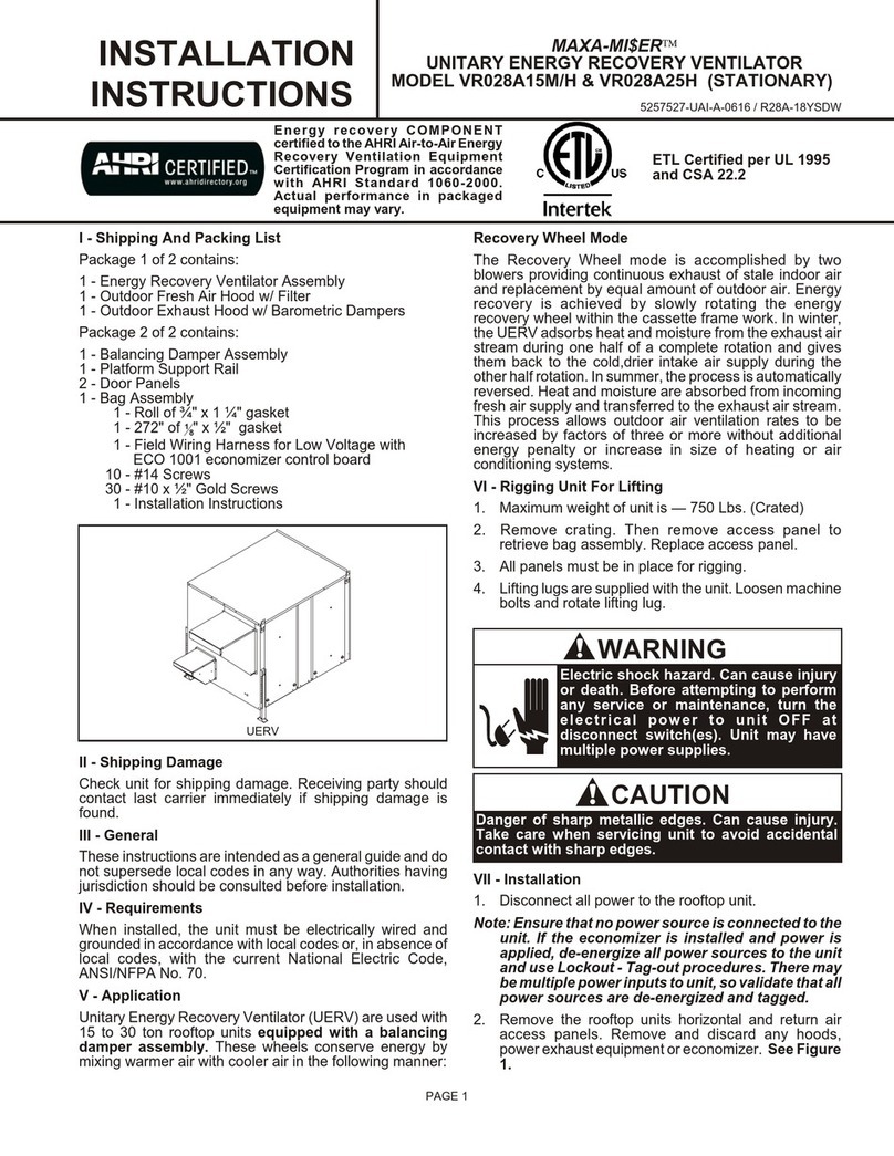
York International VR011B12H User manual

PAGE 1
I - Shipping And Packing List
Package 1 of 1 contains:
1 - Energy Recovery Ventilator
1 - Outdoor Fresh Air Hood with Filter
1 - Outdoor Exhaust Air Hood with Barometric Damper
1 - Adapter Panel
1 - Balancing Damper Assembly
1 - Platform Support Rail
1 - Top Filler Panel (VR011A12H Only)
1 - Bag Assembly
1 - Roll of ¾" x 1 ¼" gasket
1 - 272" of 18" x ½" gasket
1 - Field Wiring Harness for Low Voltage with
ECO 1001 economizer control board
- Self-tapping screws
- Gold Screws
- Installation Instructions
V - Application
Unitary Energy Recovery Ventilator (UERV)are used with
3 to 6 ton rooftop units equipped with a balancing
damper assembly. These wheels conserve energy by
mixing warmer air with cooler air in the following manner:
Recovery Wheel Mode
The Recovery Wheel mode is accomplished by two
blowers providing continuous exhaust of stale indoor air
and replacement by equal amount of outdoor air. Energy
recovery is achieved by slowly rotating the energy
recovery wheel within the cassette frame work. In winter,
the UERV adsorbs heat and moisture from the exhaust air
stream during one half of a complete rotation and gives
them back to the cold, drier intake air supply during the
other half rotation. In summer, the process is automatically
reversed. Heat and moisture are absorbed from incoming
fresh air supply and transferred to the exhaust air stream.
This process allows outdoor air ventilation rates to be
increased by factors of three or more without additional
energy penalty or increase in size of heating or air
conditioning systems.
VI - Rigging Unit For Lifting
1. Maximum weight of unit is — 537 Lbs.[Crated].
2. Remove crating and retrieve bag assembly that is
inside of UERV.
3. All panels must be in place for rigging.
4. Lifting straps are needed to lift the unit.
CAUTION
Danger of sharp metallic edges. Can cause injury.
Take care when servicing unit to avoid accidental
contact with sharp edges.
WARNING
Electric shock hazard. Can cause injury
or death. Before attempting to perform
any service or maintenance, turn the
electrical power to unit OFF at
disconnect switch(es). Unit may have
multiple power supplies.
MAXA-MI$ERÔ
UNITARY ENERGY RECOVERY VENTILATOR
MODEL VR011A12H & B12H (STATIONARY)
INSTALLATION
INSTRUCTIONS 5257541-UAI-A-0616 / R11A-29YSDW
ETL Certified per UL 1995
and CSA 22.2
Energy recovery COMPONENT
certified to the AHRI Air-to-Air Energy
Recovery Ventilation Equipment
Certification Program in accordance
with AHRI Standard 1060-2000.
Actual performance in packaged
equipment may vary.
UERV
II - Shipping Damage
Check unit for shipping damage. Receiving party should
contact last carrier immediately if shipping damage is
found.
III - General
These instructions are intended as a general guide and do
not supersede local codes in any way. Authorities having
jurisdiction should be consulted before installation.
IV - Requirements
When installed, the unit must be electrically wired and
grounded in accordance with local codes or, in the
absence of local codes, with the current National Electric
Code, ANSI/NFPA No. 70.
VII - Installation
1. Disconnect all power to the rooftop unit.
Note: Ensure that no power source is connected to the
unit. If the economizer is installed and power is
applied, de-energize all power sources to the unit
and use Lockout - Tag-out procedures. There may
be multiple power inputs to unit, so validate that all
power sources are de-energized and tagged.

2. Remove the rooftop return air access panels. Remove
and discard any hoods, power exhaust equipment, or
economizer. See Figure 1.
PAGE 2
BALANCING DAMPER
MAXA-MI$ERÔ
UNITARY ENERGY RECOVERY VENTILATOR
MODEL VR011A12H & B12H (STATIONARY)
INSTALLATION
INSTRUCTIONS 5257541-UAI-A-0616 / R11A-29YSDW
Figure 3
QUADRANT
Figure 4
Figure 1
RETURN AIR ACCESS PANEL
Figure 2
3. Locate the provided field wiring harness and the RTUs
accessory wiring bundle, separate the "com" and
"ex-fan" control wires from the accessory wiring
bundle (look for small white plugs). See Figure 2.
Figure 5
8. Connect the communication wire and power wire
located in the accessory wiring bundle in the RTU
return air section to the proper terminals on the
economizer control board (see SE field harness
diagram at the back of this manual)
9. Route the field wiring harness into the return air
section of the rooftop unit, coil the excess wire inside
the RTU in order to keep it clear during the installation
of the UERV.
10. Locate provided rolls of ¾" and 18" gasket material.
Apply ¾" gasket to the middle and bottom decks or the
UERV, apply the 18" gasket to the perimeter of the
transition assembly that connects the RTU to the
UERV.
4. Install the provided balancing damper assembly into
the return air section of the RTU. See Figure 3.
5. Adjusting the balancing damper for the minimum
airflow requirements can be done by loosening the
wingnut on the quadrant and then moving the
quadrant handle to set the return dampers in place.
See Figure 4.
6. Install SE ECO 1001 economizer control board on
balancing damper. From the RTUs accessory wiring
bundle plug the 3 wire (Red, Black, White)
Communications plug into the "SA Bus" port of the
economizer control board, plug the 2 wire exhaust fan
plug (Red, Brown) into the "24V- IN" terminal. From the
field wiring harness plug the 2 wire ERV Occupied plug
(Green, Black) into the "ex fan/ com" plug in the binary
outputs section of the board. See wiring diagram
7. Mount the SE-8001001 economizer control board in
the return air compartment on the balancing damper
frame within reach of field wiring harness. See Figure
5.

PAGE 3
MAXA-MI$ERÔ
UNITARY ENERGY RECOVERY VENTILATOR
MODEL VR011A12H & B12H (STATIONARY)
INSTALLATION
INSTRUCTIONS 5257541-UAI-A-0616 / R11A-29YSDW
Figure 8
Figure 9
TOP FILLER PANEL
Figure 7
PLATFORM SUPPORT RAIL
ADAPTOR
Figure 6
11. Locate the provided adaptor panel. Apply 18" gasket to
the perimeter of the panel to seal the contact between
the UERV and the RTU. Install the adaptor panel on
the RTU replacing the return air access panels
removed earlier and secure with provided screws,
screw holes will line up. (VR011A12H may also
require a filler panel installed after the UERV). See
Figure 6.
12. Secure the platform support rail to the bottom of the
adaptor panel using the provided screws. See Figure
7.
13. Lift the UERV at least 3' (feet), remove the 4 screws
holding each leg to its guide and pull out the legs.
Reinsert each leg from the bottom with the flat foot
under the unit then reinsert one of the screws to hold it
in place. Do not insert other screws at this time as the
legs will have to be adjusted once the unit is finally set
in place.
14. Position the UERV in front of the return air section of
the rooftop unit, line up the UERV with the adaptor
panel. See Figure 8.
15. Lower the UERV on to the platform support rail, then
secure the UERV to the adaptor panel using the
provided screws.
16. On units requiring a top filler panel install panel by
tucking the top of the panel under the top of the RTU
and angling in so that the bottom of the panel covers
the top flange of the UERV. Secure with provided
screws. See Figure 9.
Note: An equipment support or pressure treated
2x6x48" piece of wood should be placed under the
end of the UERV to prevent roof penetration by the
standoff legs.
17. Remove the screw placed in the standoff legs in Step
13 and adjust the legs on the UERV so that it is level.
Insert all 4 screws into each leg so that the legs are
secure and the UERV sits in a leveled position.
18. Check along the edges where the UERV meets the
adaptor panels and where the adapter panels meet
the RTU and seal where necessary. There should be
no air leakage and the final UERV assembly should be
weather tight. Final assembly should resemble Figure
10.
19. On the UERV open the access panel on the right side
of the name plate.
20. Connect the wiring harness to the 3 prong connector
located near the bottom of this access panel on one
end and the "ex-fan" and "com" connectors on the
other.
21. Once high voltage connections are complete and unit
is ready to start, power RTU and UERV and program
SE controller to run the UERV.

PAGE 4
MAXA-MI$ERÔ
UNITARY ENERGY RECOVERY VENTILATOR
MODEL VR011A12H & B12H (STATIONARY)
INSTALLATION
INSTRUCTIONS 5257541-UAI-A-0616 / R11A-29YSDW
Figure 11
DELTA PRESSURE
(FRESH AIR)
DELTA PRESSURE
(EXHAUST AIR)
OPTIONAL EQUIPMENT SUPPORT
Figure 10
22. All electrical connections must meet current National
Electric Codes (NEC) and/or Canadian Electric Code
(CEC). Refer closely to the wiring diagram in unit or in
these instructions for proper connections. Refer to the
units Nameplate for the minimum circuit ampacity and
the Maximum Over Current protection size. Electrical
data is listed both on the nameplates and the individual
motor nameplates.
23. Connect the line voltage power to the UERV from a
field installed power disconnect through provided ¾"
knockout. Connect line voltage to the fused power
block per wiring diagram, Figure 11 shows the control
box and wiring.
24. Ground the unit with a suitable ground connection
either through the supply wiring or and earth ground.
Units voltage entries must be sealed weather tight
after wiring is complete.
25. Restore power to the unit.
26. Start system up to verify operation.
27. Replace access panels on UERV and return air
section of the RTU and secure.
28. Cleanup once UERV is operating properly, caulk open
joints holes or seams to make the unit weather tight.
29. Fill out installation checklist and startup sheet in the
back of these instructions.
30. Leave this manual with the owner or in an envelope
inside the unit.
VIII - Operation
How It Works
The unit contains an Energy Recovery Wheel (ERW) that
is a new concept in rotary air-to-air heat exchanger.
Designed as a packaged unit for ease of installation and
maintenance, only matching up to rooftop unit with an
internal balancing damper and connection of electrical
power is required to make the system operational. The
concept consists of a unique rotary energy recovery wheel
that rotates in and out of fresh air streams within a heavy
duty, permanently installed blower cabinet that provides
ready access to all internal components. The media is
polymeric material that is coated and permanently bonded
with a dry desiccant for total enthalpy recovery. The wheel
is belt driven by PSC motor and drive belt.
When slowly rotating through counter flowing exhaust and
fresh air streams the UERV adsorbs sensible heat and
latent heat from the warmer air stream and transfer this
total energy to the cooler air stream during the second half
of its rotating cycle. Rotating at 60 revolutions per minute,
the wheel provides constant flow of energy from warmer to
cooler air stream. The large energy transfer surface and
laminar flow through the wheel causes this constant flow
of recovered energy to represent up to 85% of the
difference in total energy contained within the two air
streams.
Sensible and latent heat are the two components of total
heat. Sensible heat is energy contained in dry air and latent
heat is the energy contained within the moisture of the air.
The latent heat load from the outdoor fresh air on an air
conditioning system can often be two to three times that of
the sensible heat load and in the winter it is a significant
part of a humidification heat load.
During both the summer and winter, the UERV transfers
moisture entirely in the vapor phase. This eliminates wet
surfaces that retain dust and promote fungal growth as well
as the need for a condensate pan and drain to carry water.
Because it is constantly rotating when in the air stream, the
UERV is always being cleared by air, first in one direction
then the other. Because it is always dry, dust or other
particles impinging on the surface during one half cycle,
are readily removed during the next half cycle.
Additional Information for Options are provided in
Options Manual.
Recovery Mode
On a thermostat call for blower operation in heating,
cooling or continuous blower, the ERW will rotate between
fresh air and exhaust air streams. Both the fresh air and
exhaust air blowers will also be operating to overcome the
air resistance of the UERV.
Free Cooling Mode (optional)
The Start, Stop, Jog kit is an optional control board with
temperature and/or enthalpy sensor(s) that stops the
enthalpy wheel from spinning (and transferring heat) when
temperature conditions are conducive for free cooling.

PAGE 5
The board will spin the wheel intermittently in 10 min off 1
min on intervals to keep dust from building up on the
surface.
All units shipped with the Start, Stop, Jog option installed
have the temperature and enthalpy sensors installed, and
the jumper (J9) set to T(emp). A qualified tech can adjust
the setting to E(nthalpy) only or Temp and Enthalpy by
adjusting the jumper (J9).
The factory set points to allow for free cooling during
ventilation are 40oF-70oF, but they can be field adjusted to
narrow the band by adjusting two potentiometers while
measuring VDC between the Com & High or Com & Low
terminals (0 VDC = 40 degrees, low set point, 5 VDC = 70
degrees, high set point).
IX - System Check
1. Disconnect main power.
2. Remove control access panel and apply 24 volts to low
voltage terminal strip at "TB37-1(+) and TB37-2(-)".
3. Restore power to unit. Observe UERV wheel rotation
and both fresh air and exhaust air blower are
operating.
A - Return Damper Settings
Manually adjust position of dampers. This is accomplished
by loosing and tightening the wingnut on quadrant opening
the return dampers.
B - Blower Speed Adjustment
Blower speed selection is accomplished by changing the
sheave setting on both fresh air and exhaust air blowers.
Both blowers are factory set at "closed" for maximum
airflow. To determine air flow setting, external static
pressure readings will need to be read across the UERV.
See Figure 10 for location to take pressure readings.
C - Air Balancing Adjustment
1. Remove plastic plugs in door panels (4 total).
2. With a manometer measure the pressure drop [Inches
Of water column] across the wheel on the supply
airflow side of the unit (Top). The unit’s CFM is
determined by referring to Table #1. If the Cfm value is
not per design adjust the motor sheave until the
desired CFM is reached.
3. To adjust the exhaust airflow check the pressure on
the exhaust side of the unit (Bottom), then remove the
door panel to access the return air dampers installed
inside the RTUs return air section. Adjustment of the
damper is made by loosening the wingnut, adjusting
the damper blades and then tightening the wingnut
before closing the panel and measuring again.
4. Once desired the CFM is reached replace the plastic
plugs in the access holes in the doors.
X - Maintenance
Motor Maintenance
All motors use prelubricated sealed bearings; no further
lubrication is necessary.
MAXA-MI$ERÔ
UNITARY ENERGY RECOVERY VENTILATOR
MODEL VR011A12H & B12H (STATIONARY)
INSTALLATION
INSTRUCTIONS 5257541-UAI-A-0616 / R11A-29YSDW
Mechanical Inspection
Make visual inspection of dampers, linkage assemblies
and erv rotating bearings during routine maintenance.
Filters should be checked periodically and cleaned when
necessary. Filter is located in fresh air hoods. DO NOT
replace permanent filters with throwaway type filters.
Energy Wheel Maintenance
Four pie-shaped ERW segments are seated on stops
between the stainless steel spring retainers, secured to
the hub and rim of wheel. Annual inspection of the self
cleaning wheel is recommended. With power
disconnected, remove UERV access panels (rear) and
unplug (J150 & P150). Refer to wiring diagram in this
instruction manual. Each segment is secured in place by a
stainless steel spring retainer located on wheel rim.
Remove one end of the stainless steel spring retainer from
the slot in the wheel rim and remove. Do the same on the
next retainer. Remove segment and wash with water
and/or mild detergent. Replace segment by reversing the
above procedure. See Figure 12. Discoloration and
staining of UERV segment does not affect its performance.
Only excessive buildup of foreign material need be
removed. If the segment appears excessively dirty, it
should be cleaned to ensure maximum operating
efficiency. Thoroughly spray plastic surface with
household cleaner such as Fantasticâor equivalent
middle detergent and gently rinse with warm water using a
soft brush to remove heavier accumulation. Shake excess
water from segment and replace in reverse of removal
instructions.
HUB
SEGMENT
SPOKE
SEGMENT RETAINER CATCH
WHEEL RIM
SEGMENT RETAINER
Figure 12

MAXA-MI$ERÔ
UNITARY ENERGY RECOVERY VENTILATOR
MODEL VR011A12H & B12H (STATIONARY)
INSTALLATION
INSTRUCTIONS 5257541-UAI-A-0616 / R11A-29YSDW
York UERV Model Nomenclature
V R 028 A12 H 4 A L2 1
Wheel Type
R = Rooftop Stationary
O = Stand Alone Over and Under, Stationary
S = Stand Alone Side by Side
P = Rooftop Pivoting (036-060 & 078-150 only)
Product Category
V = Ventilator
CFM*
006 = 300 to 550
011 = 600 to 1000
020 = 1100 to 1700
028 = 2200 to 2800** 1500 to 2200**
036 = 2800 to 3600
046 = 3400 to 4600
062 = 5500 to 6200** 4800 to 5600**
074 = 6000 to 8000
122 = 8000 to 13000
York Rooftop Cabinet
A06 = Small Sunline ZF/ZR/XP036-072
A12 = 50" Predator ZF/ZH/ZR/XP*102-150, ZJ076-150
B12 = 42" Predator ZF/ZR/XP078-090, ZH0037-090, ZJ/ZR076-150
A15 = Large Sunline ZF180
A25 = Large Sunline ZF210-300, ZJ180-300, XP180-240
A40 = Millennium 25, 30 and 40 Ton Package
Blower Speed
H = High Speed**
M = Medium Speed**
V = Variable Speed
L = Constant Volume
Product Generation
1 = First Generation
Additional Options
AA = No Options Installed
L1 = Low Ambient Kit (LAK)*
L2 = LAK & MOA*
L3 = LAK & MOA & SSJ (not used on P models)*
L4 = LAK & MOA & SSJ & PS (not used on P models)
L5 = LAK & SSJ (not used on P models)*
L6 = LAK & SSJ & PS (not used on P models)
L7 = LAK & PS
L8 = LAK, MOA and PS
M1 = Motorized Outside Air (MOA)*
M2 = MOA & SSJ (not used on P models)*
M3 = MOA & SSJ & PS (PS) (not used on P models)
M4 = MOA & PS
S1 = Stop-Start-Job (SSJ) (not used on P models)*
S2 = SSJ & PS (not used on P models)
P1 = Pressure Sensor (PS)
Voltage
2= 208/230v-3ph
4= 460v-3ph
5= 575v-3ph
9= 208/320v-1ph
Duct Type
A = No Selection on Rooftop Units
PAGE 6
*CFM is ERV wheel rating. This may vary depending on unit cabinet pressure drop.
** These CFM ranges are dependant upon blower motor selection.
Low Ambient Kit (LAK) - Defrosts wheel when low ambient temp near the exhaust blower shows possible frost up.
Start-Stop-Jog (SSJ) - provides a "free cooling" mode by stopping enthalpy wheel when temps are appropriate for free
cooling.
Motorized Outside Air (MOA) damper - closes a damper on the outside air intake when the ERV is not in use.
Pressure Sensor (PS) - Analog differential pressure gauge (Magnahelic) shows pressure drop across the wheel in
Inches of Water.

PAGE 7

PAGE 8

PAGE 9
R11A-29YSDW
COMPONENT CODE
A131 Fixed Relay Board
B26 Motor, Exhaust Air
B27 Motor, Fresh Air
B28 Motor, Desiccant Wheel
B30 Motor, Damper (Optional)
B31 Motor, Damper Exhaust (Optional)
C23 Capacitor, Wheel Motor
C25 Capacitor, Motor Exhaust Air
C26 Capacitor, Motor Fresh Air
F29 Fuse
J48 Jack, Control Box (Fresh Air)
J50 Jack, Control Box (Wheel)
J51 Jack, Control Box (Exhaust Air)
J56 Jack, Control Box (Damper)
J148 Jack, Fresh Air Motor Harness
J150 Jack, Wheel Motor Harness
P153 Plug, Field Harness
P160 Plug, Damper Motor
P161 Plug, Damper Exhaust Motor Harness
RS-1 Rotation Sensor (Optional)
S26 Switch, Low Ambient (Optional)
S51 Switch, Door
S52 Switch, Damper Intake
S53 Switch, Damper Exhaust
SSJ Climate Smart Board (Optional)
T27 Transformer, Control
T28 Transformer, Step-down (Optional)
T47 Transformer, Step-down (Optional)
TB37 Terminal Block (Low Voltage)
TB38 Terminal Block (Monitoring)
TB57 Terminal Block (High Voltage)
WHL Relay, Wheel Motor
J151 Jack, Exhaust Air Motor Harness
J152 Jack, Transformer (High Voltage)
J153 Jack, Field Harness
J160 Jack, Damper Motor Harness
J161 Jack, Damper Exhaust Motor Harness
K163 Relay, Exhaust Air Motor
K164 Relay, Fresh Air Motor
MPD-1 Missing Pulse Detector Board (Optional)
P48 Plug, Fresh Air Motor Harness
P50 Plug, Wheel Motor Harness
P51 Plug, Exhaust Air Motor Harness
P56 Plug, Damper Motor Harness
P148 Plug, Fresh Air Motor
P150 Plug, Wheel Motor
P151 Plug, Exhaust Air Motor
P152 Plug, Transformer (High Voltage)
WIRE COLOR
CODE
BK Black
BL Blue
GR Green
GY Gray
OR Orange
PK Pink
RD Red
WT White
YL Yellow
Notes:
1. Remove jumper to install field optional low ambient switch.
2. Step-down transformer assembly for 460/575 volt units (only) connect between J50 and P50.
3. Selective voltage terminal for proper unit voltage.
4. Optional low ambient switch.
5. Optional motorized intake damper.
6. Optional stop, start and jog control.
7. Unit may be wired for HI, MED, or LO speeds. Diagram shows the HI speed setup, to rewire for MED or LO speed,
disconnect BK-101 from relays and connect BL-101 for MED, or RD-101 for LO. Also connect WH-101 to BK-101.
8. Optional motorized exhaust damper.
9. Optional wheel rotation sensor.
10.Optional smoke detector
11.Matching adapter harness (provided) to connect with rooftop unit.

PAGE 10
Unit#: 01-R11-01xx-21 thru -43
Desiccant Wheel for Rooftop Unit
208-230/460V/575V (1PH/3 PH)
MARGAIDGNIRIWTINUVRE
:setoN
.1 .hctiwstneibmawollanoitpodleifllatsniotrepmujevomeR
.2 .05Pdna05Jneewtebtcennoc)ylno(stinutlov575/064rofylbmessaremrofsnartnwod-petS
.3 .egatlovtinureporproflanimretegatlovevitceleS
.4 .hctiwstneibmawollanoitpO
.5 .repmadekatnidezirotomlanoitpO
.6 .lortnocgojdnatrats,potslanoitpO
.7 ,deepsOLroDEMroferiwerot,putesdeepsIHehtswohsmargaiD.sdeepsOLro,DEM,IHrofderiwebyamtinU
.101-KBot101-HWtcennocoslA.OLrof101-DRro,DEMrof101-LBtcennocdnasyalermorf101-KBtcennocsid
.8 .repmadtsuahxedezirotomlanoitpO
.9 .rosnesnoitatorleehwlanoitpO
.01 rotcetedekomslanoitpO
.11 .tinupotfoorhtiwtcennocot)dedivorp(ssenrahretpadagnihctaM

EQUIPMENT LAYOUT
PAGE 11

PAGE 12
MAXA-MI$ERÔ
UNITARY ENERGY RECOVERY VENTILATOR
MODEL VR011A12H & B12H (STATIONARY)
INSTALLATION
INSTRUCTIONS 5257541-UAI-A-0616 / R11A-29YSDW
In order for the ERV to operate with maximum
effectiveness the Smart Equipment Control (SEC) must
have the latest 3.1 (or greater) firmware installed. In order
to determine the version of firmware present within the
control follow the menu steps below.
Status> Scroll down to "Update"> Enter> View Version
If a firmware update is required be sure to perform a
backup of the units factory settings if updating the
firmware. The procedure below outlines the backup and
restore functions of the SE units control board. Once the
procedures outlined in the document, the following set
points will have been changed to the status shown below.
I - Set Points
Set Points Status BACOid
Economizer Enable ON 29747
Power Exhaust Enable ON 29787
Non-Modulating Power Exhaust ON 29503
These settings can be accessed within the RTU- SE UCB
menu. Please refer to the RTU's SE "Quick Start" guide
for menu navigation using the onboard LCD display,
joystick and enter/cancel buttons. Please see the
following pages for instructions on how to navigate
the Smart Control (SE) menus and setting up the
control to operate with an ERV.
II - SE Procedures to Backup / Restore
1. Once the packaged unit is powered up the 120 second
startup delay begins. Once the delay expires there
may or may not be a "Start Up" delay displayed. To
cancel the second time delay press the "Cancel"
button for six seconds. See Figure 1.
Startup
Figure 1
Update
Figure 2
Backup
Figure 3
2. Once the control is out of time delay mode, press the
Joystick down through the following menus: Status>
Alarms> Summary> Commission> Controller>
Update, Push ENTER (See Figure 2)
3. Once the screen and cursor are on "Update".
Press Enter and scroll through the menus until the
screen and cursor displays "Backup". If an USB flash
drive is present or is inserted into the on board USB
port, pressing enter when "Backup" is displayed the
backup will begin sending factory defaults and other
settings to the USB flash drive. See Figure 3.
4. Once the backup is performed (Screen shows BCFG
100%) the 3.1 or greater version of the controls
firmware can be loaded. Please see the details on the
following pages on how to perform the firmware
updates.
III– SE Procedures to Update
Updating the program in the SE control by USB if
required.
WARNING! In order for the ERV to properly operate with
the SE control version 3.1.0.0.0128 or greater must be
installed. Load the appropriate files to a clean USB Flash
Drive as indicated in the prior five steps.
(Files located on UPGNET>UST and Technical
Services Center>Tech Services Software Updates)

PAGE 13
MAXA-MI$ERÔ
UNITARY ENERGY RECOVERY VENTILATOR
MODEL VR011A12H & B12H (STATIONARY)
INSTALLATION
INSTRUCTIONS 5257541-UAI-A-0616 / R11A-29YSDW
1. Place USB Flash Drive into USB port on controller
(Note: Please be sure a backup to a USB drive
before updating the firmware).
Screen will read:
USB WAIT
Then:
USB OK
Controller > Update
Figure 5
Next Page…
2. Press Joy Stick down
Screen will read:
Status
>Alarms
3. Press Joy Stick lever down four times until the screen
below appears. If the Update screen is scrolled past
you return by pressing the joy stick lever up until the
Update screen appears.
Screen will read:
Contrler (Controller)
>Update
Enter & Cancel Buttons
Figure 6
>View Ver
Figure 7
>LoadFirm
Figure 8
>Confirm
Figure 9
USB: OK
Figure 4
4. Press ENTER
Screen will read:
>View Ver (Version)
Load Firm
Backup
5. Toggle Joy stick down so the arrow is next to
>Load Firm
6. Press ENTER
Screen shows software versions present on the USB
Flash Drive, such as >1.0.0.1101.secusb.pkg,
3.0.0.1072.secusb.pkg or other versions that have been
loaded onto the USB Flash Drive. Scroll up or down to view
firmware versions on the drive. Select the desired firmware
file (3.1.0.0128 version in this example).
7. Press ENTER
Screen will read:
Confirm?

PAGE 14
MAXA-MI$ERÔ
UNITARY ENERGY RECOVERY VENTILATOR
MODEL VR011A12H & B12H (STATIONARY)
INSTALLATION
INSTRUCTIONS 5257541-UAI-A-0616 / R11A-29YSDW
8. Press ENTER again.
Screen will read FWU WAIT then the program will load.
This could take up to 10 minutes or more. The screen
contents will change several times during the update so be
patient…
Wait until base screen reappears. Re-programming is
complete for the firmware. Now that the new firmware is
loaded it is time to restore the backup data from earlier
step. Scroll to: Status> Alarms> Summary>
Commission> Controller> Update> View Version>
Load Firmware> Backup> Restore press Enter and the
screen will request the user indicate which restore file to
use. The backup files should be named after the units
serial number. Scroll to the appropriate units serial number
on the screen and press Enter. The restore should only
take 15-20 seconds. Once the restore is complete the SE
unit control will reboot. Note: If updating a version "H"
board it may require two firmware updates to take
place. Please verify the active version of firmware after
updating.
If the unit does not reboot, restart cycle power to the unit
and wait again for re-boot start-up.
If loading more than one file, example upgrading CDR unit
from version 1, you should cycle power after loading the
first file and again after the last file is complete.
It is a good practice to conduct a "RE-LEARN" from within
the menu after the file(s) have been upgraded if the
function of the unit does not appear to be normal. Status>
Alarms> Summary> Commission> Controller>
IV - SE Procedures to Setup Operation for ERV
In order for the SE unit controller, SE economizer control
and ERV to operate properly the following
changes/settings will need to be performed within the SE
unit control.
1. Scroll through menus by pressing down on joystick:
Status> Alarms> Summary> Commission> Econ>
Economizer Enable- Make sure this is set to "Yes"
ERV-En
Figure 11
Econ-En
Figure 10
3. The economizer minimum setting must be set at 50%
or greater.
Status> Alarms> Summary> Commission>
PowerEx> ERV Enable- Make sure this is set to
"Yes"
4. Once the ERV is set to "Enable" the ERV will operate
any time the unit is in the occupied mode. The ERV, if
equipped with pivoting wheel, will rotate the wheel out
of the air stream anytime the packaged units
economizer enters the free cooling mode. In order to
test for proper operation the unit must see a call for
cooling (24 vac on the Y1 terminal) and an outdoor
temperature of 55oF or less. If the outdoor ambient
temperature is above 55oF the unit may not enter free
cooling. If the ambient temperature is above 55oF the
packaged unit can be forced into free cooling mode by
doing the following:
5. Scroll through menus by pressing down on joystick:
Status> Alarms> Summary> Commission>
Controller> Update> Details,
under details press Enter then scroll to the Service
menu heading, press Enter then scroll to Inputs>
NetworkInputs, scroll to NetOAT and change it to a
setting well below the 55oF default by toggling the
joystick left or right to increase/decrease the value,
then pressing Enter to store the new value. If the
setting is now 30oF for example the unit should go into
free cooling mode within a few minutes of the
change. Note: Once the NetOAT is forced to a
temperature below 55oFit will remain at the forced
value for 15 minutes and revert back to default
settings.
For additional details on navigating, changing and
operating the SE unit control board please refer to the
SE (Smart Equipment) Controls Quick Start Guide
(Document # 1136326-USG-C-0216) that is shipped
with the packaged unit.
2. Scroll through menus by pressing down on joystick:
Status> Alarms> Summary> Commission>
PowerEx> ERV Enable- Make sure this is set to
"Yes"

PAGE 15
MAXA-MI$ERÔ
UNITARY ENERGY RECOVERY VENTILATOR
MODEL VR011A12H & B12H (STATIONARY)
INSTALLATION
INSTRUCTIONS 5257541-UAI-A-0616 / R11A-29YSDW
This Page Intentionally Left Blank

START UP INFORMATION SHEET
VOLTAGE - UERV UNIT
Incoming Voltage L1-L2 L1-L3 L2-L3
Running Voltage L1-L2 L 1-L3 L2-L3
Secondary Voltage C (black) to G (green) Volts*
C (black) to W (white) Volts*
* With thermostat calling.
AMPERAGE - UERV MOTORS
Intake Motor: Nominal HP Rated Amps Running Amps
Exhaust Motor: Nominal HP Rated Amps Running Amps
Wheel Motor: Nominal HP Rated Amps Running Amps
AIRFLOW
Intake Design CFM Pressure Drop Calculated CFM
Exhaust Design CFM Pressure Drop Calculated CFM
Amb. db Temp Return Air db Temp* Tempered Air db Temp*
Amb. wb Temp Return Air wb Temp* Tempered Air wbTemp*
* Measure after 15 minutes of run time
INSTALLATION CHECK LIST
UERV Model # Serial #
Owner Owner Phone #
Owner Address
Installing Contractor Start Up Mechanic
qInspect the unit for transit damage and report any damage on the carrier's freight bill.
qCheck model number to insure it matches the job requirements.
qInstall field accessories and unit adapter panels as required. Follow accessory and unit installation manuals.
qVerify field wiring, including the wiring to any accessories.
qCheck all multi-tap transformers, to insure they are set to the proper incoming voltage.
qVerify correct belt tension, as well as the belt/pulley alignment. Tighten if needed.
qPrior to energizing the unit, inspect all the electrical connections.
qPower the unit. Bump the motor contactor to check rotation. Three phase motors are synchronized at the
factory. If blower motor fans are running backwards, de-energize power to the unit, then swap two of the three
incoming electrical lines to obtain proper phasing. Re-check.
qPerform all start up procedures outlined in the installation manual shipped with the unit.
qFill in the Start Up Information as outlined on the opposite side of this sheet.
qProvide owner with information packet. Explain the thermostat and unit operation.
York International Corporation
5005 York Drive
Norman, OK 73069
Subject to change without notice. Printed in U.S.A.
Copyright © 2016 by Johnson Controls, Inc. All rights reserved.
5257541-UAI-A-0616 / R11A-29YSDW
Supersedes: None
This manual suits for next models
1
Table of contents
Other York International Fan manuals