Yosemite MIAH36S User manual

1
Installation Instructions
35.5" (90.17 CM) ISLAND RANGE HOOD(Installation Instructions and Use & Care Guide)
For more details visit our website at: http://www.yosemitehomedecor.com
For questions about features, operation/performance, parts, accessories or service,
call: 1-800-305-9872
USE AND CARE GUIDE ISLAND HOOD

2
We are pleased that you have chosen Yosemite Home Décor island range hood and we hope
you are enjoying the convenience, quality, and affordability of your new range hood. This
instruction manual is part of our mission to ensure maximum customer satisfaction and
complete product safety.
Finding Information
Please carefully read the following important information regarding installation safety and
maintenance. Keep this information booklet accessible for further consultations.
TABLE OF CONTENTS
IMPORTANT SAFETY INSTRUCTIONS
3
INSTALLATION REQUIREMENTS
4
Location Requirements
4
Installation Dimensions
4
Venting Requirements
4
Electrical Requirements
5
INSTALLATION INSTRUCTIONS
5
Prepare Location
5
Range Hood Installation
5
USE AND MAINTENANCE
7
TROUBLE SHOOTING
9
Correct Disposal of this product
9
WARRANTY INFORMATION
10
IMPORTANT: READ AND SAVE THESE INSTRUCTIONS FOR RESIDENTIAL USE ONLY

3
IMPORTANT SAFETY INSTRUCTIONS
Your safety, and the safety of others, is very important
Safety Precaution :
Take care when the hood is operating simultaneously with an open fireplace or burner that depend on the air in the
environment, as the hood removes the air from the environment which a burner or a fireplace needs for combustion.
Provide adequate ventilation in the environment for a safe operation of the hood. Follow the local laws applicable for
external air evacuation.
Control the data plate (positioned inside the appliance) to ascertain that the voltage and power correspond to the
network and the socket is suitable. If in doubt ask a qualified electrician.
Installation work and electrical wiring must be done by qualified person(s) in accordance with all applicable codes
and standards, including fire-rated construction.
If the hood is not properly grounded, any electrical appliances can go off.
Young children should be supervised to ensure they do not play with the appliance.
Do not check the status of the filters while the cooker hood is operating.
Do not touch bulbs or adjacent areas, during or straight after prolonged use of the lighting installation.
Avoid free flame, as it is damaging for the filters and a fire hazard.
Before servicing or cleaning the unit, switch power off at service panel and lock the service disconnecting means to
prevent power from being switched on accidentally. When the service disconnecting means cannot be locked,
securely fasten a prominent warning device, such as a tag, to the service panel.
When cutting or drilling into wall or ceiling; do not damage electrical wiring and other utilities.
Ducted fans must always be vented outdoors.
CAUTION: For general ventilating use only. Do not use to exhaust hazardous or explosive materials and vapors.
CAUTION: To reduce risk of fire and to properly exhaust air, be sure to duct air outside - do not vent exhaust air
into spaces within walls or ceilings, attics or into crawl spaces, or garages.
WARNING: TO REDUCE THE RISK OF FIRE, USE ONLY METAL DUCTWORK.
WARNING: TO REDUCE THE RISK OF A RANGE TOP GREASE FIRE:
Never leave surface units unattended at high settings. Boil overs cause smoking and greasy spillovers that may
ignite. Heat oils slowly on low or medium settings.
Always turn hood ON when cooking at high heat or when flaming food (i.e. Crepes Suzette, Cherries Jubilee, and
Peppercorn Beef Flambé).
Clean ventilating fans frequently. Grease should not be allowed to accumulate on fan or filter.
Use proper pan size. Always use cookware appropriate for the size of the surface element.

4
INSTALLATION REQUIREMENTS
Location Requirements
Venting Requirements
-Hood location should be away from strong draft
areas, such as windows, doors and strong heating
vents.
-Because of the size and weight of this island hood,
there needs to be cross bracing in the attic to support
the hood and it must be securely attached to the
ceiling. (Figure 1)
-All openings in ceiling and wall where range hood
will be installed must be sealed.
Figure 1
-Grounded electrical outlet isrequired (See “Electrical
Requirements” section). If the hood is not properly
grounded, any electrical appliances can go off.
Installation Dimensions
Figure 2
IMPORTANT:
Distance “C” is recommended to be between 28” and 32”.
Distance B can vary between 26.5” and 46”.
■Vent system must terminate to the outside, except for non-
vented (recirculating) installations.
■Do not terminate the vent system in an attic or other enclosed
area.
■Do not use 4" (10.2 cm) laundry-type wall caps.
■Use metal vent only. Rigid metal vent is recommended. Do
not use plastic or metal foil vent.
■The vent system must have a damper. If the roof or wall cap
has a damper, do not use the damper supplied with the range
hood.
Venting Methods
This island hood is factory set for venting through the roof.
A 6" (15.2 cm) round vent system is needed for installation (not
included). The hood exhaust opening is 6" (15.2 cm) round.
NOTE: Flexible vent is not recommended. Flexible vent creates
back pressure and air turbulence that greatly reduce
performance.
Vent system can terminate either through the roof or wall. To
vent through a wall, a 90° elbow is needed.
Figure 3
NOTE: Wall venting can be an option for 2-story homes.

5
Electrical Requirements
Observe all governing codes and ordinances. Ensure that the
electrical installation is adequate and in conformance with
National Electrical Code, ANSI/NFPA 70 (latest edition), or
CSA Standards C22.1-94, Canadian Electrical Code, Part 1
and C22.2 No. 0-M91 (latest edition) and all local codes and
ordinances.
If codes permit and a separate ground wire is used, it is
recommended that a qualified electrician determine that the
ground path is adequate.
A 110 volt, 60 Hz, 15-amp, fused electrical circuit is required.
IMPORTANT:Before connecting the model to the electricity network:
Control the data plate (positioned inside the appliance) to
ascertain that the voltage and power correspond to the network
and the socket is suitable. If in doubt ask a qualified electrician
■If the house has aluminum wiring, follow the procedure
below:
1. Connect a section of solid copper wire to the pigtail
leads.
2. Connect the aluminum wiring to the added section of
copper wire using special connectors and/or tools
designed and UL listed for joining copper to aluminum.
The appliance has been manufactured as a class I,
therefore earth cable is necessary.
The connection to the mains is carried out as follows:
IEC227
North America
L= live
Brown
Black
N= neutral
Blue
White
E= earth
Green/Yellow
Green
If not provided, connect a plug for the electrical load indicated
on the description label. Where a plug is provided, the cooker
hood mustbe installedinorderthat the plug is easilyaccessible.
An omnipolar switch with a minimum opening of 3mm between
contacts, in line with the electrical local and local standards,
must be placed between the appliance and the network in the
case of direct connection to the electrical network.
INSTALLATION INSTRUCTIONS
Prepare Location
■Lay out the vent duct system before installing the range hood
to determine the best routing for the vent duct.
■It is recommended that the vent system be installed before
the range hood is installed.
■Before making cutouts, make sure there is proper clearance
within the ceiling for exhaust vent.
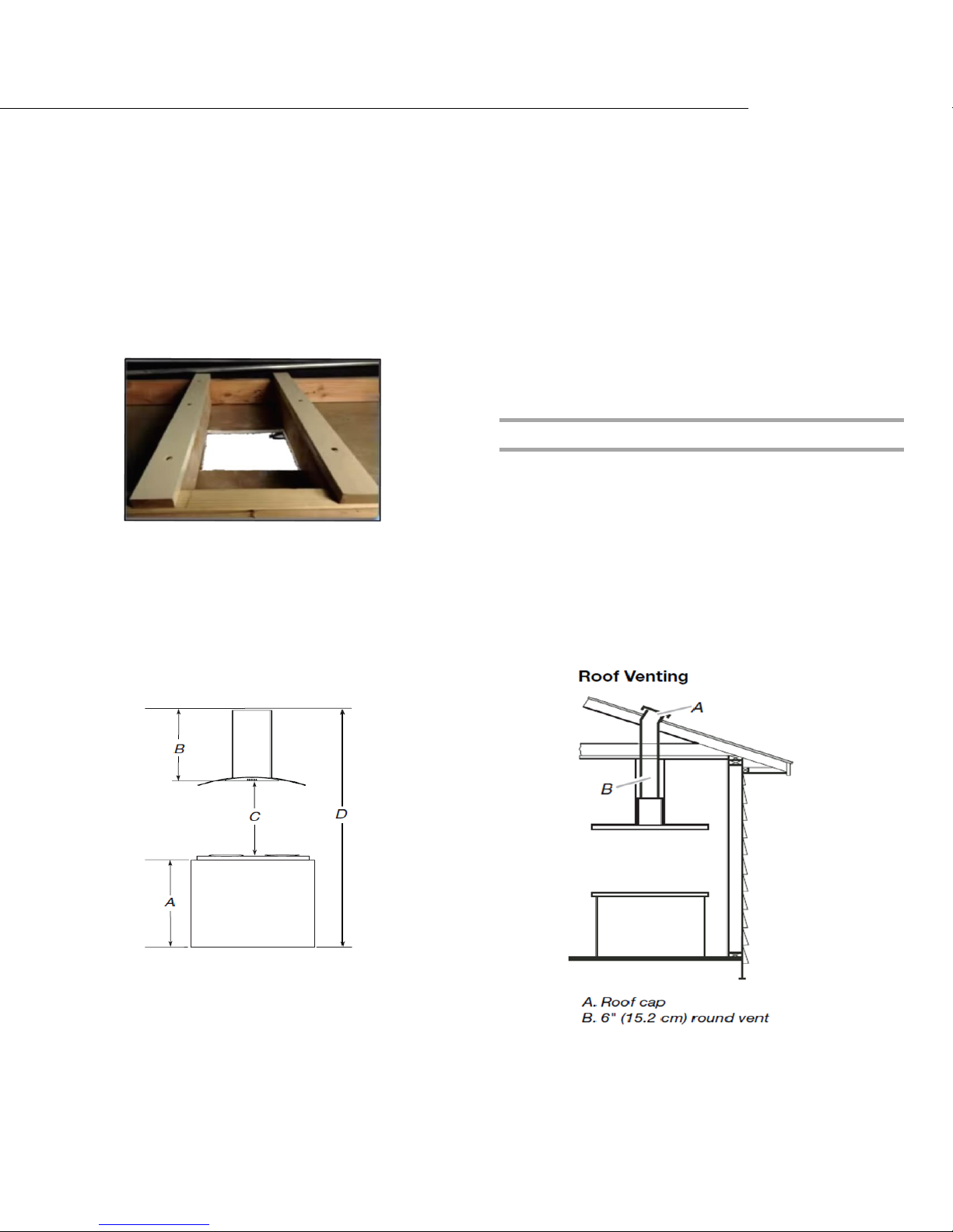
■Check your ceiling height and the range hood height
maximum before you install your hood.
1. Disconnect power.
2. Determine which venting method to use: roof or wall.
3. Select a flat surface for assembling the range hood.
4. Place covering over that surface.
Using 2 or more people, lift range hood onto covered spacers
Range Hood Installation-Inspect your range hood to make sure there is no
damage during the shipping.
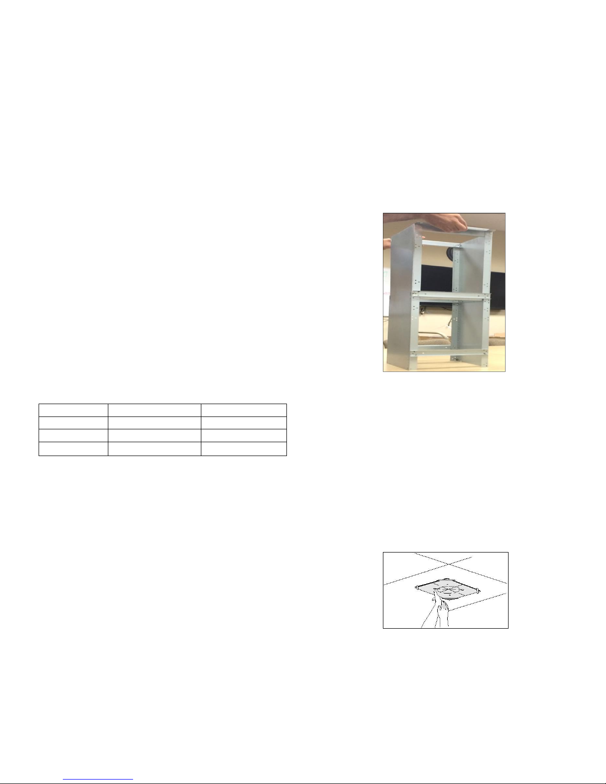
-Remove the telescopic structure from the packaging
and separate the upper part from the lower one.( Figure
4)
Figure 4
-Make the center point directly above your cooktop where
the range hood will be installed.
-Place the upper part on the ceiling around the center
point. Make sure it is square with your cooktop.
-Trace the outline of the upper part on the ceiling and
also use a pencil to mark the mounting screws.
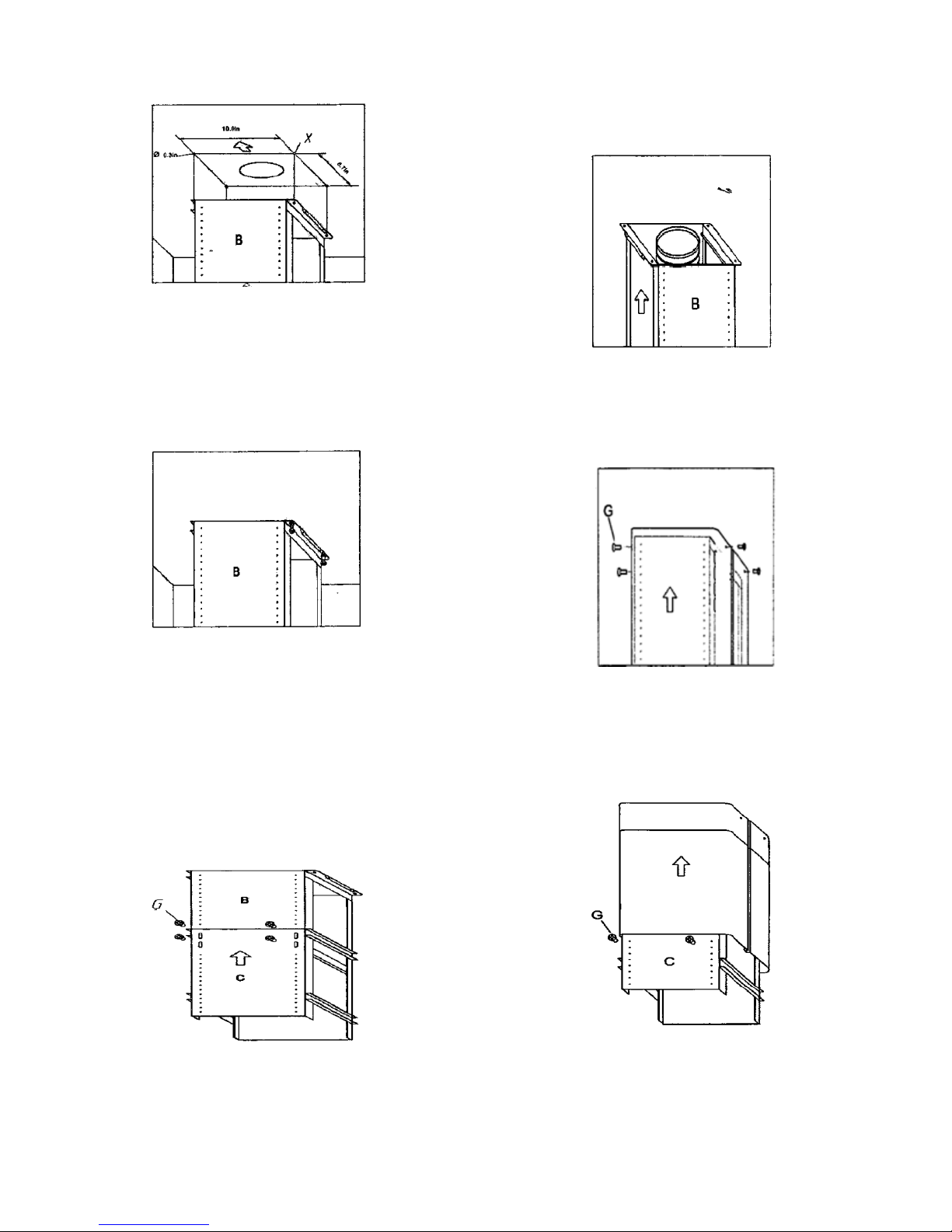
-Remove the upper part and trace a circle where the
ducting will go and then cut out the center part of the
circle on the ceiling. (Figure 5)
-
Figure 5
-Make 4, Ø8 holes in the ceiling (marked points) and drive
in 3 screws without completely tightening them (Figure
6).
Pay attention not to insert the screw into the hole
marked with an X on the hole template (the screws and

6
expansion plugs must be suitable for the type of wall).
Figure 6
-Take the upper part of the telescopic structure
(structure B) and insert 3 slots onto the 3 screws that
are not completely tightened and then rotate slightly to
fit. (Figure 7).
Figure 7
-Drive in the fourth screw X and tighten the remaining 3
to allow definitive blocking of the upper part of structure
B.
-Take the lower part of the telescopic structure C and
insert it into the upper part structure B.
-Adjust the height and block it using the 8 units screws
G that are supplied. (Figure 8)
Figure 8
Suction version:
-Fix the pipe to the hole we made on the ceiling (or
prepared air evacuation hole). (Figure 9).
Figure 9
-Take the upper part chimney piece and fix it with 4
unit screws G. (Figure 10).
Figure 10
-Take the lower chimney and fix it with 2 unit screws
G, drive in hood to avoid it down. (Fig.11).
Figure 11
-Insert the suction unit inside the structure and set in 4
mounting hole, drive in 4 units screw N (Figure 12).

7
Figure 12
-Fix the air evacuation pipe H (not supplied) onto the
connection flange. (Fig. 13)
Figure 13
-Unscrew the 2 screws G and rest the lower chimney
piece above the hood. (Fig 14)
Figure 14
-If the hood is supplied with a lower chimney piece that
must be fixed to the hood body with screws, remove
the anti-grease filters from the hood by acting on the
relevant handles (Figure15). Then screw the lower
chimney piece pipe to the inside of the hood, using
screws P (Figure 16).Relocate the filters in their seat.
Figure15
Figure 16
USE AND MAINTENANCE
It is recommended to operate the appliance prior to
cooking.
It is recommended to leave the appliance in operation
for 15 minutes after cooking is terminated in order to
completely eliminate cooking vapors and odors.
The proper function of the hood is conditioned by the
regularity of the maintenance operations, in particular,
the active carbon filter.
The anti-grease filters capture the grease particles
suspended in the air, and are therefore subject to
clogging according to the frequency of the use of the
appliance.
In order to prevent fire hazard, it is recommendable to
clean the filter at a maximum of 2 months by carrying
out the following instructions:
-Remove the filters from the hood and wash them in a
solution of water and neutral liquid detergent, leaving to
soak.
-Rinse thoroughly with warm water and leave to dry.
-The filters may also be washed in the dishwasher.
The aluminum panels may alter in color after several
washes. This is not cause for customer complaint nor
replacement of panels.
The active carbon filters purify the air that is replaced in
the environment. The filters are neither washable nor
reusable and must be replaced at maximum every four
months. The saturation of the active carbon filter

8
depends on the frequency of use of the appliance, by
the type of cooking and regularity of cleaning the anti-
grease filters. (Figure 17)
Figure 17
To remove the charcoal filters place on hand on one
filter at a time and turn it toward the front part. The
charcoal filter can now be removed. Always ensure to
replace both filters at the same time.
Clean the fan and other surfaces of the hood regularly
using a cloth moistened with denatured alcohol or non-
abrasive liquid detergent.
The illumination installation is designed for use during
cooking and not for prolonged general illumination of
the environment. Prolonged use of the illumination
installation notably reduces the duration of the bulb.
Use a one-edge screwdriver or any other appropriate
tool to lift and remove the overhead light fixture.
Replace the damaged lamp. Use only halogen lamps
as the original specification, avoiding contact with
hands. Return the light fixture to its position (snap
fastening). (Figure 18)
Figure 18
COMMANDS:
A= Timer (automatic shut off)
B= Speed 1/ adjust/ switch off
C= Digital display screen (showing timer and speed)
D= Speed 3/ adjust / switch off
E= Light
When pursuing A, digital display screen shows “15 minutes” for
timer, and the minutes can be adjusted by pushing “+” or “-“on B
and D. And the first speed is on, pushing A once to switch off,
the digital display shows “00”. When pushing B, it shows “F1” on
the digital display screen, and the first speed is on. Pushing B
once to switch off, and the digital display shows “00”.
When pushing D, it shows “F3” on the digital display screen,
and the third speed is on. Pushing D twice to switch off and it
shows “00” on the screen. The second speed F2 and Turbo
speed F4 can be adjusted by pushing B or D.
When pushing E, the buttons light is on and the light is on, only
push E once again to switch off the light.

9
Trouble Shooting
Problem
Possible reason
Solution
Hood doesn’t work
No electric supply
Check the plug is connected
Check the main switch is turned on
Poor airflow
Aluminum grease filters
clogged
Clean the filters and replace when dry
Charcoal filters clogged
Replaced the charcoal filters
Motor running but no air flow
Butterfly valve jammed
Contact technician
Motor cuts after a few minutes
High temperature safety
device activated
The kitchen is not sufficiently ventilated
The hood is installed too
near the cooking stove
The hood must be least 25.6 in from stove
Strong cooking smell
Charcoal filters not
installed
In re-circulating mode, charcoal filters must
be installed
Oil dripping onto stove
Oil cup missing or not
installed
Remove aluminum filter and replace oil cup
Aluminum grease filter
saturated
Wash the aluminum filters
Whirring sound
Something in contact with
fan blade
Contact with technician
THE MANUFACTUREORY DECLINES ALL RESPONSIBILITIY FOR EVENTUAL DAMAGES CAUSED BY BREACHING
THE ABOVE WARNINGS.
Correct Disposal of this product
This marking indicates that this product should not be disposed with other household wastes throughout
the EU. To prevent possible harm to the environment or human health from uncontrolled waste disposal,
recycle it responsibly to promote the sustainable reuse of materialresources. To return your used device,
please use the return and collection systems or contact the retailer where the product was purchased.
They can take this product for environmental safe recycling.

10
Warranty Information
The manufacturer provides warranty in accordance with the legislation of the customer’s own country
of residence, with a minimum of 1 year (Germany: 2 years), starting from the date on which the
appliance is sold to the end user
The warranty only covers defects in material or workmanship.
The repairs under warranty may only be carried out by an authorized service center. When making a
claim under the warranty, the original bill of purchase (with purchase date) must be submitted
-The warranty will not apply in case of:
-Normal wear and tear
-Incorrect use, e.g. overloading of the appliance, use of non-approved accessories
-Use of force, damage caused by external influences
-Damage caused by non-observance of the user manual, e.g. connection to an unsuitable mains
supply or non-compliance with the installation instructions
-Partially or completely dismantled appliances
Other manuals for MIAH36S
1
Table of contents
Other Yosemite Ventilation Hood manuals
Popular Ventilation Hood manuals by other brands

Franke
Franke FSMD 508 installation manual

Zanussi
Zanussi IH6013 Instructions for use and care

NuTone
NuTone Range Master RM50000 Series manual

Whirlpool
Whirlpool GZ8336XLS Installation Instructions and Use & Care Guide

Faber
Faber CRISTAL installation instructions

Kenmore
Kenmore 51840 Operating instructions and parts list

Kleenmaid
Kleenmaid KCRHSO6010 Instructions for use and warranty details

Faber
Faber GEMMA PB SRM X A60 user manual

Multikomplex
Multikomplex SLT966-EM Installation, Use and Maintenance Instruction

Smeg
Smeg SHT600X instruction manual

Best
Best WPP9 Instructions for use and maintenance

Electrolux
Electrolux U312940. EFC70710 user manual