Seenergy T-SPOT ISOLA User manual

COOKER HOOD - User instructions
ODSAVAČ PAR-Návod k použití
EMHÆTTE - Brugervejledning
LIESITUULETIN - Käyttöohje
ΑΠΟΡΡΟΦΗΤΗΡΑΣ ΣΕ ΕΚΟΣΗ ΑΠΟΡΡΟΦΗΣΗΣ - Εγχειρίδιο χρήση
ELSZÍVÓ KÜRTŐ - Használati utasítás
AVTREKKSKAPPE - Bruksanvisning
OKAP ZASYSAJĄCY - Instrukcja obsługi
HOTĂ ASPIRANTĂ - Manual de utilizare
-
SPISKÅPA - Bruksanvisning
CZ
DK
FIN
GR
H
N
PL
R
RUS
S
GB
T-SPOT ISOLA


- 3 -
AC
max 80 cm
B
X
B
A
B
Fig.4
Fig.2 Fig.3
Fig.1

- 4 -
F
H
Fig.7
Fig.5 Fig.6
Fig.8
- 5 -
B
1
2
F
Fig.10
Fig.9

- 6 -
A
B
H
1
2
I
M
H
Fig.14
Fig.11 Fig.13
Fig.12

- 7 -
Fig.19
Fig.17 Fig.18
Fig.16
Fig.20
Fig.15

- 8 -
ABDE
CF
Fig.23
Fig.22Fig.21

- 9 -
ENGLISH GB
GENERAL
Carefully read the following important information
regarding installation safety and maintenance. Keep
this information booklet accessible for further con-
sultations.The appliance has been designed for use in
the ducting version (air exhaust to the outside - Fig.1B),
filtering version (air circulation on the inside - Fig.1A)
or with external motor (Fig.1C).
SAFETY PRECAUTION
1.Take care when the cooker
hood is operating simultaneously
with an open fireplace or burner
that depend on the air in the
environment and are supplied
by other than electrical energy,
as the cooker hood removes the
air from the environment which
a burner or fireplace need for
combustion. The negative pres-
sure in the environment must not
exceed 4Pa (4x10⁻⁵ bar). Provide
adequate ventilation in the envi-
ronment for a safe operation of
the cooker hood. Follow the local
laws applicable for external air
evacuation.
Beforeconnecting the modelto
the electricity network:
-Control the data plate (posi-
tioned inside the appliance) to
ascertain that the voltage and
power correspond to the network
and the socket is suitable. If in
doubt ask a qualified electrician.
-If the power supply cable is dam-
aged, it must be replaced with
another cable or a special assem-
bly, which may be obtained direct
from the manufacturer or from
the Technical Assistance Centre.
2. Warning!
Incertain circumstanceselectri-
cal appliances may be a danger
hazard.
A) Do not check the status of
the filters while the cooker
hood is operating.
B) Do not touch bulbs or adja-
cent areas, during or straight
after prolonged use of the
lighting installation.
C) Flambècooking is prohibited
underneath the cooker hood.
D) Avoid free flame, as it is
damaging for the filters and a
fire hazard.
E) Constantly check food frying
to avoid that the overheated oil
may become a fire hazard.
F) Disconnect the electrical
plug prior to any maintenance.
G) This appliance can be used
by children aged from 8 years
and above and persons with
reduced physical, sensory or
mental capabilities or lack of
experience and knowledge
if they have been given
supervision or instruction
concerning useofthe appliance
inasafewayandunderstandthe
hazardsinvolved.Childrenshall
not play with the appliance.
Cleaning andusermaintenance
shall not be made by children w
thout supervision.
H) Young children should be
supervised to ensure they do
not play with the appliance.
I) There shall be adequate ven-
tilation of the room when the
rangehood is used at the same
time as appliances burning gas
or other fuels.
L) There is a risk of fire if clean-
ing is not carried out in accord-
ance with the instructions.
INSTALLATION INSTRUCTIONS
-
nections must be carried out by
specialised personnel.
- 10 -
proceeding with the installa-
tion.
Note!Verify the data label placed inside the appliance:
-If the symbol appears on the plate, it means that
no earth connection must be made on the appliance,
therefore follow the instructions concerning insulation
class II.
-If the symbol DOES NOT appear on the plate, follow
the instructions concerning insulation class I.
Insulation class II
-The appliance has been manufactured as a class II,
therefore no earth cable is necessary.The plug must be
easily accessible after the installation of the appliance.
If the appliance is equipped with power cord without
plug, a suitably dimensioned omnipolar switch with
3 mm minimum opening between contacts must be
fitted between the appliance and the electricity supply
in compliance with the load and current regulations.
-The connection to the mains is carried out as follows:
BROWN = Lline
BLUE = Nneutral.
Insulation class I
This is a class I, appliance and must therefore be
connected to an effiecient earthing system.
-The appliance must be connected to the electricity
supply as follows:
BROWN = Lline
BLUE = Nneutral
YELLOW/GREEN = earth.
The neutral wire must be connected to the terminal
with the N symbol while the YELLOW/GREEN, wire
must be connected to the terminal by the earth
symbol .
When connecting the appliance to the electricity
supply, make sure that the mains socket has an earth
connection. After fitting the ducted cooker hood, make
sure that the electrical plug is in a position where it
can be accessed easily. If the appliance is connected
directly to the electricity supply, an omnipolar switch
with a minimum contact opening of 3 mm must be
placed in between the two; its size must be suitable
for the load required and it must comply with current
legislation.
If the hob is electric, gas, or induction, the minimum
distance between the same and the lower part of the
hood must be at least 65 cm. If a connection tube
composed of two parts is used, the upper part must
be placed outside the lower part. Do not connect
the cooker hood exhaust to the same conductor
used to circulate hot air or for evacuating fumes
from other appliances generated by other than an
electrical source. Before proceeding with the assembly
operations, remove the anti-grease filter(s) (Fig.15) so
that the unit is easier to handle.
- In the case of assembly of the appliance in the suction
version prepare the hole for evacuation of the air.
We recommend the use of an air exhaust tube which
has the same diameter as the air exhaust outlet hole.
If a pipe with a smaller diameter is used, the efficiency
of the product may be reduced and its operation may
become noisier.
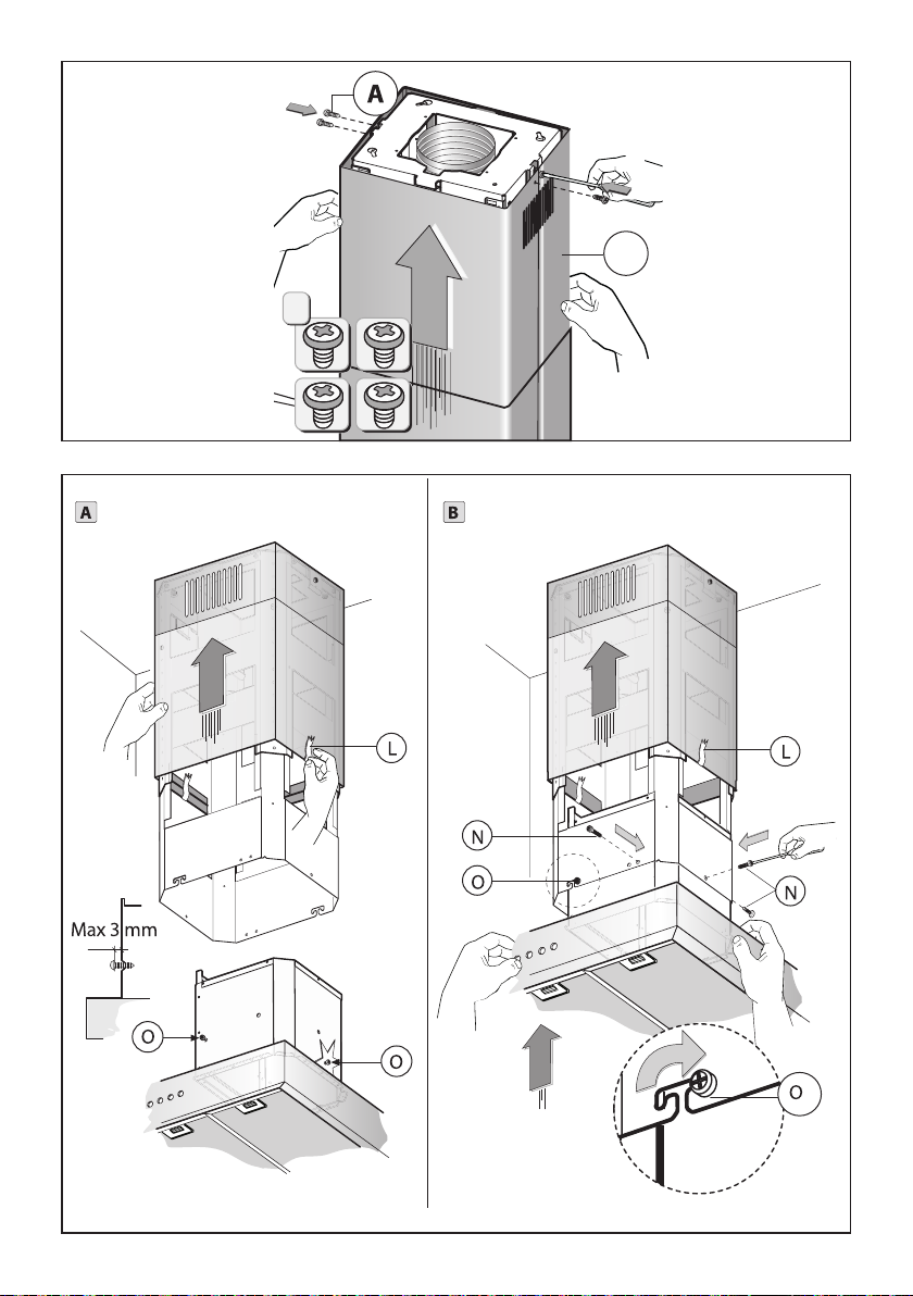
-Remove the structure from the packaging and remove
the 2 screws A to separate the upper part from the
lower part (Fig.2).
-Position hole template on the ceiling paying atten-
tion that the arrow is positioned on the same side
as the appliance controls (Fig.3). Make 4, Ø8 holes in
the ceiling and drive in 3 screws without completely
tightening them. Pay attention not to insert the screw
into the hole marked with an X on the hole template
(the screws and expansion plugs must be suitable for
the type of wall).
-Take the upper part of the structure B(Fig.4) and insert
the 3 slots onto the 3 screws that are not completely
tightened. Rotate slightly to fit (Fig.4). Drive in the
fourth screw X and tighten the remaining 3 to allow
definitive blocking of the upper part of structure B.
-Take the lower part of the telescopic structure C and
insert it into the upper structure B (Fig.5). Adjust the
height by referring to the amounts indicated in (Fig.15)
and block it using the 8 screws Gthat are supplied
(Fig.6).
fix the air evacuation pipe H (not
supplied) onto the connection flange F (Fig.8). Fix
the flexible pipe to the prepared air evacuation hole
(Fig.12).
we have two different types of Kit,
one with extractable carbon filters (Fig.16) and the
other one with re-usable carbon filters (washable)
(Fig.17).
-Fix the air evacuation pipe H (not supplied) onto the
connection flange F (Fig.8).
-If your product is fitted with a connector flange,
perform the assembly steps indicated in fig. 7 before
fixing the cooker hood to the structure.Take connector
flange Fand fit it to the upper part of the cooker hood
suction assembly using the 2 screws E(Fig.7).
-Take the upper chimney piece and fix it to the struc-
ture using the screws A (Fig.9). Join the lower chimney
piece with the upper one and fix it carefully using
adhesive tape L (Fig.10A).
-Unscrew the 2 screws O, max 3 mm (Fig.10A). Insert
the suction unit inside the structure paying attention
that the previously unscrewed screws O, hook into the
slots in the lower part as indicated in (Fig.10B). Drive
in the 3 screws N (supplied) and tighten the 2 screws
O(Fig.10B).
-Remove adhesive tape L and rest the lower chimney
piece above the cooker hood (Fig.11X).
- Lower the upper chimney by performing the reverse
operation shown in figure 9.
-If the cooker hood is supplied with a lower chimney
piece that must be fixed to the hood body with screws,
remove the anti-grease filters from the hood by acting
on the relevant handles (Fig.15).
-If necessary, fix the lower duct to the hood from the
inside, using the screws P (Fig.11Y). Re-locate the filters
in their seat.
-Fix the flexible pipe to the deflector Mand fix screw I
as indicated in Fig.13, the active carbon filters must be
applied to the suction unit positioned inside the hood
(Fig.16).

- 11 -
USE AND MAINTENANCE
We recommend that the cooker hood is switched
on before any food is cooked. We also recommend
that the appliance is left running for 15 minutes after
the food is cooked, in order to thoroughly eliminate
all contaminated air. The effective performance of
the cooker hood depends on constant maintenance;
the anti-grease filter and the active carbon filter both
require special attention.
is responsible retaining the
grease particles suspended in the air, therefore it is
subject to clogging with variable frequency according
to the use of the appliance.
- To prevent the danger of possible fires, at least every 2
months one must wash the anti-grease filters by hand
using non-abrasive neutral liquid detergents or in the
dishwasher at low temperatures and on short cycles.
- After a few washes, colour alterations may occur.This
does not give the right to claim their replacement.
are used to purify the air
that is sent back into the room and its function is to
mitigate the unpleasant odours produced by cooking.
- The non-regenerable active carbon filters must be
replaced at least every 4 months.The saturation of the
active charcoal depends on the more or less prolonged
use of the appliance, on the type of kitchen and on the
frequency with which anti-grease filter is cleaned.
- Regenerable active charcoal filters must be washed
by hand, with non abrasive neutral detergents, or
in the dishwasher at a maximum temperature of
65°C (the washing cycle must be complete without
dishware). Remove excess water without damaging
the filter, remove the plastic parts, and let the mat
dry in the oven for at least 15 minutes approximately
at a maximum temperature of 100°C. To keep the
regenerable charcoal filter functioning efficient this
operation must be repeated every 2 months. These
must be replaced at least every 3 years or when the
mat is damaged.
regenerable active charcoal filters it is important
that they are completely dry.
externally, using a cloth dampened with denatured
alcohol or neutral liquid detergents that are non
abrasive.
The lighting .system is designed for use during
cooking and not for the prolonged general lighting
of the room.The prolonged use of the lighting system
significantly decreases the average duration of the
bulbs.
If the appliance is equipped with courtesy lights it is
possible to use them for general room lighting for a
prolonged amount of time.
the non compliance with the hood
cleaning warnings and with the replacement and
cleaning of the filters entails risk of fires. One therefore
recommends keeping to the suggested instructions.
In order to replace the dichroic lamps, carefully remove
the lamp from the lamp holder with the help of a small
flat screwdriver or a similar tool.
PLEASE NOTE! In doing this operation, please take
care not to scratch the hood.
Replace the bulbs with new ones of the same type.
To replace the halogen light bulbs B, remove the
glass pane
Cusing a lever action on the relevant cracks.
Replace the bulbs with new ones of the same type.
Caution: do not touch the light bulb with bare hands.
If the appliance version is with LED lamps, the inter-
vention of a specialised technician is necessary to
replace them.
the key symbols areexplained
below:
A= LIGHT
B= OFF
C= SPEED I
D= SPEED II
E = SPEED III
F = AUTOMATIC STOP TIMER - 15 minutes
If your appliance has the INTENSIVE speed function,
from speedTHREE, press key Efor 2 seconds and it will
be activated for 6 minutes after which it will return to
the previously set speed. When the function is active
the LED flashes.
To interrupt it before the 6 minutes have elapsed, press
key Eagain. Some models allow activating this function
even with speed one and two.
By pressing key F for two seconds (with the hood
switched off) the“clean air”function is activated. This
function switches the appliance on for ten minutes
every hour at the first speed. As soon as this function
is activated the motor starts up at the first speed for
ten minutes. During this time key F and key C must
flash at the same time. After ten minutes the motor
switches off and the LED of key F remains switched on
with a fixed light until the motor starts up again at the
first speed after fifty minutes and keys F and C start to
flash again for ten minutes and so on. By pressing any
key for the exclusion of the hood light the hood will
return immediately to its normal functioning (e.g. if key
Dis pressed the“clean air”function is deactivated and
the motor moves to the 2nd speed straight away. By
pressing key B the function is deactivated).
The “AUTOMATIC STOP TIMER”delays stopping
of the hood, which will continue functioning for 15
minutes at the operating speed set at the time this
function is activated.
-When the Akey flashes with a 2 second frequency
the anti-grease filters must be washed.
-When the Akey flashes with a 0.5 second frequency
the active carbon filters must be replaced or washed
depending on the type of filter.
Once the clean filter has been put back one must reset
the electronic memory by pressing the Akey for ap-
proximately 5 seconds until it stops flashing.
Fig.22) the key symbols are
explained below:
A = LIGHT
B = OFF
C = SPEED I

- 12 -
D = SPEED II
E = SPEED III
G= MOTOR WORKING indicator
NOTE: with this command it is also possible to control
the appliance using a remote control, to be requested
as an accessory.
A Button = Switches the hood on/off. The equipment
switches on at the 1st speed.
B Button = Decreases motor speed.
C Display = Shows the selected motor speed and timer
activation/intense speed/filter warning.
D Button = Increases motor speed.
Pressing the 4th speed button engages the intense
function for 6 minutes, then the equipment goes back
to working at the speed at which it was activated. Du-
ring this function, the number 4 flashes on the display.
-If you wish to deactivate the function before the 6
minutes, press the B button.
Attention! Some models only work up to the 3rd
speed and, therefore, do not have the intense function.
E Button = Pressing this button activates the Timer
function even with any of the 1-2-3 speeds engaged
(except the Intense function speed). When the Timer
function is active, the set speed must flash on the
display when the timer is activated.
After 15 minutes, at the end of the countdown, the
hood switches off (motor and any lights remain on).
If the intense speed is engaged, the Timer cannot be
activated.
-If you wish to deactivate the function before the 15
minutes, press the Ebutton.
F Button = Switches the lights on/off.
-After 30 h of operation, when the Cdisplay flashes,
alternating the working speed with the letter F(i.e.
2and F), this means that you need to wash the anti
grease filters.
-After 120 h of operation, when the Cdisplay flashes,
alternating the working speed with the letters C/F (i.e.
2and C/F), this means that you need to wash or replace
the charcoal filters.
-Once you have repositioned the clean filter, you need
to reset the electronic memory with the hood on,
pressing the Bbutton for about 3 seconds.
After that time, the letter Eappears on the display
(reset confirmed) and the hood switches off.
THE MANUFACTURER DECLINES ALL
RESPONSIBILITY FOR EVENTUAL DAMAGES
CAUSED BY BREACHING THE ABOVE WARNINGS.

- 13 -
ČESKY CZ
ÚVOD’
Přečtěte si pozorně obsah návodu, protože poskytuje
důležité informace týkající se bezpečné instalace,
používání i údržby zařízení. Uchovejte si návod pro ja-
koukoliv budoucí potřebu. Přístroj je určen kodsávání
(odvádění vzduchu ven-Obr.1B), filtrování (recyklace
vzduchu vmístnosti-Obr.1A) nebo kpoužití sexterně
umístěným motorem (Obr.1C).
BEZPECNOSTNÍ OPATRENÍ
1.Vyžaduje se opatrnost, jestliže
jsou současně v činnosti odsávač
par a jiný hořák nebo tepelné
zařízení závisející na vzduchu
místnosti a napájené jinou energií
než elektrickou, protože odsávač
par spotřebovává vzduch z okolí,
který hořák nebo jiné tepelné za-
řízení potřebují ke spalování. Ne-
gativní tlak nesmí překročit 4Pa
(4x10⁻⁵ bar). K bezpečnému pro-
vozu je tedy nutná odpovídající
ventilace místnosti. Při odvádění
vzduchu do vnějšího prostředí je
nutné se řídit platnými předpisy
Vaší země.
Před napojením modelu na
elektrickou síť:
-Zkontrolujte tabulku súdaji
umístěnou uvnitř přístroje a
ověřte si, že napětí a výkon odpo-
vídají místní síti a rovněž zásuvka
je vhodná. Vpřípadě jakékoliv
pochyby se poraďte skvalifiko-
vaným elektrikářem.
-Jeli napájecí kabel poškozen,
musí být nahrazen speciálním
kabelem nebo sadou, které jsou
k dispozici u výrobce nebo vjeho
servisním středisku.
2. Upozornění!
V některých situacích mohou
být elektrická zařízení zdrojem
nebezpečí.
A)Nekontrolujte stav filtrů, za-
tímco je odsavač v činnosti.
B)Nedotýkejte se žárovek a při-
lehlých prostor během dlouho-
dobého použití osvětlení nebo
bezprostředně po něm.
C)Je zakázánopřipravovatjídla
na plameni pod odsavačem.
D)Vyhněte se použití volných
plamenů, protože poškozují
filtry a mohou způsobit požár.
E)Udržujte neustále pod kon-
trolou smažení jídel, aby se
zabránilovznícenírozpáleného
oleje.
F)Před zahájením údržby od-
pojte zástrčku ze zásuvky elek-
trického rozvodu.
G)Tento přístroj může být
používán dětmi ve věku nad
8 let a osobami sesníženými
psycho-fyzickými-smyslovými
nebo duševními schopnostmi
nebo bez patřičnýchzkušeností
a znalostí, pokud jsou pod
pečlivým dohledem nebo
byly seznámeny s pokyny k
použití přístroje bezpečným
způsobem a rozumí jeho
rizikům. Zkontrolujte, zda
si děti nehrají s přístrojem.
Čištění a údržba, které mají být
vykonávány uživatelem, nesmí
být prováděny dětmi, pokud
nejsou pod dohledem.
H)Dohlížejte na děti, abyste si
byli jisti, že si nehrají se zaříze-
ním.
I)Kdyžjeodsavačpoužívánsou-
časně se zařízeními spalujícími
plyn nebo jiná paliva, místnost
se musí vhodně větrat.
L)Když nebudou řádně prove-
deny úkony údržby, existuje
riziko vzniku požáru.
NÁVOD K INSTALACI
elektrická napojení musí být
- 14 -
provedeny pouze odborným
personálem.
pro provádění operací montá-
že.
Poznámka! Zkontrolujte štítek umístěný uvnitř zařízení:
-Když se na štítku nachází symbol , znamená to, že
zařízení nesmí být uzemněno, postupujte tudíž podle
pokynů týkajících se třídy izolace II.
-Když na štítku NENÍ uveden symbol , postupujte
dle pokynů týkajících se třídy izolace I.
Třída izolace II
Zařízení je vyrobeno v II. třídě, a proto žádný vodič
nesmí být uzemněn.
Po instalaci zařízení musí být zástrčka snadno pří-
stupná.
Vpřípadě, že je zařízení vybaveno kabelem bez
zástrčky, je pro jeho připojení do elektrického roz-
vodu třeba mezi zařízení a elektrický rozvod zapojit
omnipolární stykač sminimální vzdáleností kontaktů
3 mm, navržený pro příslušnou zátěž a odpovídající
platným normám.
Napojení k elektrické síti musí být provedeno násle-
dovně:
HNĚDÁ = Lvodič
MODRÁ = N neutrální vodič.
Třída izolace I
Toto zařízení je vyrobeno ve třídě I, a proto musí být
připojeno kuzemnění.
Připojení kelektrické síti musí být provedeno násle-
dovně:
HNĚDÝ = Lfázový vodič
MODRÝ = Nnulový vodič
ŽLUTO/ZELENÝ =zemnicí vodič.
Nulový vodič musí být připojen ke svorce označené
symbolem N, zatímco ŽLUTO/ZELENÝ vodič musí být
připojen ke svorce nacházející se vblízkosti symbolu
uzemnění .
Během operace elektrického zapojení se ujistěte, zda je
elektrická zásuvka vybavena uzemněním. Po uskuteč-
nění montáže odsavače dávejte pozor, aby byla poloha
zástrčky elektrického přívodu snadno dostupná.Vpří-
padě přímého zapojení kelektrické síti je třeba mezi
zařízení a elektrickou síť zapojit omnipolární stykač
sminimální vzdáleností kontaktů 3 mm, navržený
pro příslušnou zátěž a odpovídající platným normám.
Minimální vzdálenost mezi opěrnou plochou varných
nádob na varném zažízení a nejnižším bodem kuchyň-
ského krytu musí být alespoň 65 cm. Vývod odsavače
nesmí být napojen na vývod, ve kterém cirkuluje teplý
vzduch, nebo který je používán k odvádění kouře ze
zařízení napájených jinou energií než elektrickou. Před
zahájením montáže vyjměte z odsavače tukový filtr
(Obr.15). Usnadníte si tak manipulaci spřístrojem.
- Vpřípadě montáže přístroje ve verzi odsávače je třeba
připravit otvor kevakuaci vzduchu.
Doporučuje se použít trubku pro odvádění vzduchu
se stejným průměrem jako hrdlo výstupu vzduchu.
Použití redukce by mohlo negativně ovlivnit vlastnosti
výrobku a zvýšit hlučnost.
-Vyjměte celou strukturu zobalu a odstraňte dva
šroubyA za účelem oddělení horní části od části spodní
(Obr.2).
-Umístěte vrchní část děrování na strop a dávejte
pozor, aby se šipka nacházela na stejné straně, kde se
nachází ovládání přístroje (Obr.3). Vytvořte 4 otvory
Ř8 do stropu a zašroubujte 3 šrouby bez toho, abyste
je zcela utáhli a dávejte pozor, abyste nezašroubovali
šroub do otvoru označeného Xna vrcholu děrování
(šrouby a roztahovací špalíčky musí být vhodné pro
typ stěny).
-Uchopte horní část struktury B(Obr.4) a umístěte ji
na 3 šrouby, jež nebyly zcela zašroubovány vsouladu
střemi otvory. Proveďte malou rotaci za účelem začle-
nění (Obr.4). Zašroubujte čtvrtý šroub Xa dotáhněte
ostatní tři šrouby, čímž umožníte definitivní upevnění
horní části struktury B.
-Uchopte spodní část teleskopické struktury Ca
začleňte ji do vrchní struktury B(Obr.5). Nastavte
požadovanou výšku sohledem na vzdálenosti určené
na (Obr.14) a zablokujte ji pomocí 8 šroubů Gvdotaci
(Obr.6).
Připevněte trubku pro evakuaci
vzduchu H(která není vdotaci) ke spojovací přírubě
F(Obr.8).upevněte ohebnou trubku kpředem připra-
venému otvoru kevakuaci vzduchu (Obr.12).
máme k dispozici dva odlišné druhy sad,
jednu s kazetovými uhlíkovými filtry (Obr.16) a druhou
s filtry s regeneračním uhlíkem (umývatelné) (Obr.17).
-Připevněte trubku pro evakuaci vzduchu H(která není
vdotaci) ke spojovací přírubě F(Obr.8).
-V případě, že je váš produkt dodán vybavený spojo-
vací přírubou, před upevněním odsavače ke struktuře
proveďte montáž znázorněnou na Obr.7. Vezměte spo-
jovací přírubu F a namontujte ji v horní části odsávací
jednotky odsavače prostřednictvím 2 šroubů E(Obr.7).
-Uchopte horní komín a upevněte jej na strukturu
pomocí 2 šroubů A(Obr.9). Připojte spodní komín
khornímu a upevněte jej pozorně lepicí páskou L
(Obr.10A).
-Odšroubujte o max 3 mm 2 šrouby O(Obr.10A).Včleň-
te odsávací skupinu dovnitř struktury a ověřte si, že se
šrouby O, jež byly předem odšroubovány, zaháknou
do otvorů ve spodní části, jak je uvedeno na (Obr.10B).
Zašroubujte 3 šrouby N(v dotaci) a dotáhněte 2 šrouby
O (Obr.10B).
-Odstraňte lepicí pásku La položte spodní komín na
těleso krytu (Obr.11X).
-Spusťte horní komín zpětným postupem uvedeným
na obrázku 9.
- Pokud je váš přístroj vybaven spodním komínem,
který vyžaduje upevnění ktělesu krytu pomocí šroubů,
odstraňte zkrytu protitukové filtry pomocí určených
rukojetí (Obr.15).
-V případě potřeby připevněte zevnitř spodní komín
k odsavači s použitím šroubů P(Obr.11Y). Nakonec
uveďte protitukové filtry do jejich původní polohy.
-Napojte ohebnou trubku na deflektor Ma upevněte
šroub I, jak je uvedeno na Obr.13, filtry zaktivního uhlí
musí být aplikovány na odsávací skupinu umístěnou
uvnitř krytu (Obr.16).

- 15 -
POUŽITÍ A ÚDRŽBA
Doporučujeme uvést zařízení do činnosti ještě před
zahájením přípravy jakéhokoli jídla. Doporučujeme
ponechat zařízení včinnosti i po dobu 15 minut po
ukončení přípravy jídel, aby byl kompletně odveden
zapáchající vzduch. Správná činnost odsavače je
podmíněna správnou a nepřetržitou údržbou; zvláštní
pozornost je třeba věnovat protitukovému filtru a filtru
saktivním uhlím.
Protitukový filtr má za úkol zachycovat mastné
částice nacházející se ve vzduchu, proto je vprůběhu
proměnné doby vystaven ucpávání; tato doba závisí
na používání zařízení.
- Abyste předešli případnému nebezpečí požáru, je
nutné nejméně jednou za dva měsíce nutné proplách-
nout filtry proti mastnotě v ruce pomocí neutrálních
neabrazivních čisticích prostředků nebo v myčce na
nádobí při nízkých teplotách v krátkém mycím pro-
gramu.
- Po několika mytích může dojít ke změně barvy.Tento
jev neopravňuje k reklamaci pro eventuální výměnu.
slouží pro pročištění
vzduchu, který se vypouští do prostředí a pohlcují
nepříjemné zápachy, které vznikají během vaření.
- Aktivní uhlíkové filtry, které nelze regenerovat, je
zapotřebí měnit každé 4 měsíce. Saturace aktivního
uhlíku závisí více-méně od délky používání přístroje,
typu kuchyně a pravidelnosti, se kterou se provádí
čištění filtru proti mastnotě.
- Aktivní uhlíkové filtry, které lze regenerovat, je možné
mýt v rukou pomocí čistících neutrálních a neabraziv-
ních prostředků, anebo je možné je mýt v myčce na
nádobí s maximální teplotou 65°C (cyklus mytí se musí
provádět bez nádobí). Odstraňte přebytek vody bez
toho, že byste poškodili filtr, odstraňte části z plastů
a nechte vysušit podložku v rouře po dobu přibližně
15 minut o teplotě maximálně 100°C. Pro udržování
funkčnosti uhlíkového filtru s možností regenerace je
zapotřebí zopakovat tuto operaci každé 2 měsíce.Tyto
filtry se musí vyměnit jednou za 3 roky anebo když je
podložka poškozena.
mastnotě a aktivních uhlíkových filtrů, které lze
regenerovat, je důležité, aby byli pořádně suché.
-
užitím hadru navlhčeného v denaturovaném lihu
neboneabrazivních tekutýchčisticíchprostředcích.
Osvětlení je navrženo pro použití během vaření a ne
pro dlouhodobější použití za účelem osvětlení okolní-
ho prostředí. Dlouhodobější použití osvětlení výrazně
snižuje průměrnou životnost žárovek.
Pokud je přístroj vybaven osvětlením prostředí, toto
může být používáno pro všeobecné dlouhodobé
osvětlování daného prostředí.
Pozor: nedodržování pokynů k čištění odsavače a
výměny a čištění filtrů zapříčinit rizika požáru. Dopo-
ručuje se proto dodržovat tyto pokyny.
Při výměně dychroických žárovek odpojte žárovku
tak, že ji opatrně uvolníte zobjímky spomocí malého
plochého šroubováku nebo odpovídajícího nástroje.
UPOZORNĚNÍ! Během této operace dávejte pozor,
abyste nepoškrábali odsavač.
Žárovky nahraďte novými žárovkami stejného druhu.
Obr.19):
Při výměně halogenových žárovek Bsejměte sklíčko
C po jeho nadzvednutí v místě příslušných otvorů.
Žárovky nahraďte novými žárovkami stejného druhu.
Upozornění: nedotýkejte se žárovky holýma rukama.
Je-li verze výrobku vybavena žárovkami LED pro jejich
výměnu je potřebný zásah specializovaného technika.
Obr.21):
Tlačítko A= OSVĚTLENÍ
Tlačítko B= VYPNUTÍ
Tlačítko C= PRVNÍ RYCHLOST
Tlačítko D= DRUHÁ RYCHLOST
Tlačítko E = TŘETÍ RYCHLOST
Tlačítko F =
ČASOVÝ SPÍNAČ AUTOMATICKÉ VYPNUTÍ 15
minut
Pokud je vaše zařízení již vybaveno funkcí VYSOKÉ
rychlosti, pak při přepnutí na třetí rychlost a stisku
tlačítka Epo dobu 2 sekund bude na 6 minut tato
vysoká rychlost aktivována, a potom se zařízení vrátí
k provozu na dříve nastavenou rychlost.
Když je funkce aktivní, kontrolka LED bliká.
Pro přerušení režimu před uplynutím 6 minut znovu
stiskněte tlačítko E.
U některých modelů je možno funkci aktivovat také na
první a druhé rychlosti.
Po stisknutí tlacítka F po dobu 2 s (kryt je vypnut)
bude aktivována funkce “clean air”. Tato funkce za-
pne motor na deset minut každou hodinuna první
rychlost. Jakmile bude tato funkce aktivována, motor
bude uveden do chodu na první rychlost po dobu 10
s, behem které budou blikat soucasne tlacítka F a C.
Po uplynutí této doby se motor vypne a led tlacítka F
zustane osvetlen až do doby, kdy po 50 minutách bude
znovu motor uveden do chodu na první rychlost a led
F a C znovu zacnou blikat po 10 minut a tak dále. Stisk-
nutím kteréhokoli tlačítka, kromě tlačítek osvětlení, se
odsavač vrátí ke svému normálnímu fungování (např.
stisknutím tlačítka Dse deaktivuje funkce “clean air”
a motor se nastaví na 2° rychlost; stisknutím tlačítka B
se funkce deaktivuje).
Funkce“ČASOVÝ SPÍNAČ AUTOMATICKÉ VYPNU-
TÍ”opožďuje vypnutí odsávače, který bude pokračovat
ve funkci pracovní rychlostí, která byla nastavena
vokamžiku zapnutí této funkce, 15 minut.
uhlím:
-Blikání tlačítka A frekvencí 2 sek. poukazuje na po-
třebu umytí protitukových filtrů.
-Když tlačítko Abliká s frekvencí 0,5 sek., filtry s aktiv-
ním uhlíkem je třeba umýt anebo vyměnit v závislosti
od typu filtru.
Po vložení čistého filtru je třeba vynulovat elektronic-
kou paměť stisknutím tlačítka Ana dobu přibližně 5
sek., dokud tlačítko nepřestane blikat.
Tlačítko A= OSVĚTLENÍ
Tlačítko B = VYPNUTÍ
Tlačítko C = PRVNÍ RYCHLOST

- 16 -
Tlačítko D= DRUHÁ RYCHLOST
Tlačítko E = TŘETÍ RYCHLOST
Tlačítko G= Wskaźnik
POZNÁMKA: s tímto příkazem můžete kontrolovat
přístroj s dálkovým ovládáním, které je dostupné jako
příslušenství.
Tlačítko A = Zapne/vypne odsavač par. Přístroj se za-
pne při 1. rychlosti.
Tlačítko B = Sníží rychlost motoru.
Displej C = Indikuje zvolenou rychlost motoru a ak-
tivaci časovače/intenzivní rychlosti/signalizace filtrů.
Tlačítko D = Zvýší rychlost motoru.
Stisknutím tlačítka 4. rychlosti se aktivuje intenzivní
rychlost po dobu 6 minut, poté se přístroj vrátí na
provozní rychlost, nastavenou před aktivací. Během
této funkce na displeji bliká číslo 4.
-Chcete-li deaktivovat funkci dřív, než uplyne 6 minut,
stiskněte tlačítko B.
Pozor! Některé modely pracují jenom po 3. rychlost,
intenzivní rychlost není k dispozici.
Tlačítko E = S jakoukoliv vloženou rychlostí 1-2-3
(vyjma intenzivní rychlosti 4) se stisknutím tlačítka
aktivuje funkce Timer (časovač). Když je funkce ča-
sovače aktivní, na displeji musí blikat rychlost, která
byla nastavena v okamžiku aktivace časovače.
Po 15 minutách na konci počítání se odsavač par vy-
pne ( motor a eventuální světla zůstanou zapnuty).
Je-li aktivní intenzivní rychlost, časovač nelze spustit.
-Chcete-li deaktivovat funkci dřív, než uplyne 15 mi-
nut, stiskněte tlačítko E.
Tlačitko F = Zapne/zhasne světla.
-Po 30 hodinách provozu, když na displeji Cstřída-
vě bliká provozní rychlost s písmenem F (např. 2a F),
znamená to, že je nezbytné umýt protitukové filtry.
-Po 120 hodinách provozu, když na displeji Cstřída-
vě bliká provozní rychlost s písmenem C/F (např.2a
C/F),, znamená to, že je nezbytné umýt nebo vymě-
nit uhlíkové filtry .
- Po umístění čistého filtru je nezbytné resetovat elek-
tronickou paměť při zapnutém odsavači par stisknu-
tím tlačítka B po dobu asi 3 sek.
Po uplynutí této doby se na displeji objeví písmeno
E (potvrzení provedeného resetu) a odsavač par se
vypne.
VÝROBCEODMÍTÁJAKOUKOLIVZODPOVĚDNOST
ZA ŠKODY ZPŮSOBENÉ NEDODRŽENÍM UVEDE
NÝCH UPOZORNĚNÍ.

- 17 -
DANSK DK
GENERELLE OPLYSNINGER
Læs omhyggeligt indholdet af denne brugsanvisning,
da den giver vigtige oplysninger vedrørende sik-
kerheden ved installering, brug og vedligeholdelse.
Opbevar brugsanvisningen til senere brug. Apparatet
er udarbejdet til at kunne fungere; udsugende (udled-
ning af luft til eksterne omgivelser Fig.1B), filtrerende
(intern cirkulation af luft Fig.1A) og med udvendig
motor (Fig.1C).
OPLYSNINGER VEDRØRENDE SIKKERHED
1.Udvis forsigtighed hvis der
samtidigt med emhætten er en
varmekilde eller flamme i funk-
tion, som er afhængig af luften
i omgivelserne og forsynet med
energi, der ikke er elektrisk, ef-
tersom emhætten fjerner den
luft fra omgivelserne, som flam-
men eller varmekilden har brug
for til forbrænding. Det negative
tryk i lokalet må ikke overstige 4
Pa (4x10⁻⁵ bar). For størst mulig
sikkerhed, sørg for en passende
ventilation af rummet. Hvad
angår udsugningen til eksterne
omgivelser følg de gældende
normer.
Før modellen tilslutteselnettet:
-Kontrollèr informationsetiketten
(placeret indeni apparatet), for at
sikre, at spændingen og styrken
er i overensstemmelse med el-
nettet og at stikkontakterne er
egnede. Hvis De er i tvivl, konsul-
tèr en kvalificeret elektriker.
-Hvis forsyningsledningen er be-
skadiget, skal den udskiftes med
en ledning eller en særlig samling
fra fabrikanten eller et autoriseret
servicecenter.
2.Pas på!
I nogle situationer kan elektri-
ske apparater udgøre en fare.
A)Undgå at kontrollere filtre-
nes tilstand mens emhætten er
i funktion.
B)Rør ikke ved pærer eller til-
stødende områder under eller
lige efter længerevarende brug
af belysningsanlægget.
C)Det er ikke tilladt at tilberede
madvarer for åben ild under
emhætten.
D)Undgå åben ild, da det kan
beskadige filtrene og medføre
fare for brand.
E)Hold altid øje med maden
under friturestegning for at
undgå, at olien antændes.
F)Træk stikket ud af stikkon-
takten, inden der foretages
vedligeholdelse.
G)Dette apparat kan bruges
af børn, der mindst er 8 år
gamle, og af personer med
nedsatte psykiske, fysiske og
sensoriske evner, eller med
en utilstrækkelig erfaring og
kendskab hvis de er under
oversyn og har modtaget
anvisninger til sikker brug af
apparatet og har kendskab til
de dermed forbundne risici.
Sørg for at børn ikke leger
med apparatet. Rengøring og
vedligeholdelse der tilkommer
brugeren må ikke foretages af
børn uden opsyn.
H)Hold øje med børnene for at
sikre, at de ikke leger med ap-
paratet.
I)Når emhætten anvendes
samtidigt med apparater, der
bruger gas eller andre brænd-
stoffer, skal rummet have til-
strækkelig udluftning.
L)Hvis rengøring ikke udføres
i overensstemmelse med an-
visningerne, kan det medføre
brandfare.

- 18 -
INSTRUKTION VED INSTALLERING
af de elektriske forbindelser,
skal udføres af specialiseret
personale.
monteringen,skal man iføre sig
beskyttelseshandsker.
Bemærk! Kontroller typeskiltet inden i apparatet.
-Hvis der på skiltet findes symbolet , betyder det,
at apparatet ikke skal jordes. Følg anvisningerne for
isoleringsklasse II.
-Hvis der på skiltet IKKE vises symbolet , skal man
følge anvisningerne for isoleringsklasse I.
Isoleringsklasse II
Apparatet er udarbejdet i klasse II, derfor skal der ikke
tilsluttes et kabel til jordforbindelsen.
Man skal nemt kunne nå ind til stikket efter installation
af apparatet.
Hvis apparatet er udstyret med ledning uden stik, skal
man ved tilkobling til strømforsyningen sørge for, at
der mellem apparatet og strømforsyningen er installe-
ret en flerpolet afbryder med en åbning på minimum
3mm mellem kontakterne, som passer til belastningen
og overholder de gældende regler.
Tilslutning til el-nettet skal udføres som følgende:
BRUN = L Fase
BLÅ = NNeutal.
Isoleringsklasse I
Dette apparat er konstrueret i klasse I og skal derfor
tilsluttes til et stik med jordforbindelse.
Tilslutningen til strømforsyningen skal udføres på
følgende måde:
BRUN = L Fase
BLÅ = NNeutal
GUL/GRØN = jord.
Den neutrale ledning skal tilsluttes til klemrækken med
symbolet N mens den GUL/GRØNNE skal tilsluttes til
klemrækken ud for jordsymbolet .
Når den elektriske tilslutning udføres, skal man sikre
sig, at strømstikket har jordforbindelse. Efter monte-
ring af emhætten skal man sikre sig, at stikkontakten
nemt kan nås.Ved direkte tilslutning til strømforsynin-
gen skal der mellem apparatet og strømforsyningsnet-
tet monteres en flerpolet afbryder med en mini-
mumsafstand mellem kontakterne på 3mm, der kan
klare belastningen og overholder de gældende regler.
Minimums distancen mellem kogeoverfladen,
målt fra selve kogepladerne, og den nederste del af
emhætten, skal være mindst 65 cm. Hvis der anvendes
et forbindelsesrør bestående af to eller flere dele, skal
den øverste del placeres udenpå den nederste. Tilslut
ikke udledningen fra emhætten med et rør, hvori der
cirkulerer varm luft eller som anvendes til at udlede røg
fra apparater, der ikke bruger elektrisk energi. Inden
man begynder monteringen fjernes filtret (Fig.15) for
at gøre håndteringen af apparatet lettere.
-I de tilfælde, hvor apparatet skal installeres i en udsu-
gende version, forberedes åbningen til udledning af
luft.
Det anbefales at anvende en luftudsugningsslange
med samme diameter som luftudgangshullet. Hvis
der anvendes en mindre slange, kan det forringe
produktets ydelse og medføre øget støj.
-Tag strukturen ud af emballagen og fjern de 2 skruer
A, for at adskille den øverste del fra den nederste
(Fig.2).
-Placèr loftsbeslaget i loftet og sørg for, at pilen ven-
der mod samme side, som apparates kontrolpanel
(Fig.3). Lav 4 huller Ø8 i loftet og skru de 3 skruer i,
uden at stramme dem helt og være opmærksom på,
ikke at placere en skrue i hullet afmærket med et Xpå
loftsbeslaget (skruer og ravplugs skal være egnede til
mur-typen).
-Tag den øverste del af strukturen B (Fig.4) og placèr
den mod de 3 ikke helt fastskruede skruer i overens-
stemmelse med de 3 huller. Drej en lille smule, til den
er fastgjort (Fig.4). Skru den fjerde skrue Xi og stram
de 3 resterende, for helt at blokere den øverste del af
strukturen B.
-Tag den nederste del af den teleskopisk formet struk-
tur C og indfør den i den øverste del B (Fig.5). Indstil
den ønskede højde ifølge de angivne tal i (Fig.14) og
fastgør den ved hjælp af de 8 medfølgende skruer G
(Fig.6).
fastgør røret til udlednng af
luft H(ikke inklusiv) til pakningen F(Fig.8). Fastgør det
bøjelige rør til den åbning, som er lavet til udledning
af luft (Fig.12).
der findes to forskellige typer
sæt - et med kassette-kulfiltre (Fig.16) og et med gen-
brugskulfiltre (vaskbare) (Fig.17).
-Fastgør røret til udlednng af luft H(ikke inklusiv) til
pakningen F(Fig.8).
-Hvis produktet er udstyret med en samleflange,
skal monteringen vist i Fig.7 først udføres, inden det
fastgøres til rammestrukturen.Tag samleflangen F, og
monter den i den øverste del af udsugningsdelen på
emhætten med de 2 skruer E(Fig.7).
-Tag den øverste del af skorstenen og fastgør den til
strukturen ved hjælp af de 2 skruer A(Fig.9). Foren den
nederste del af skorstenen med den øverste og fastgør
den forsigtigt med et stykke tape L(Fig.10A).
-Løsn de 2 skruer O (Fig.10A) max 3 mm. Anbring den
udsugende del indeni rørstrukturen og vær opmærk-
som på, at skurerne O, som før blev løsnede, passes ind
i hullerne på den nederste del, som angivet i (Fig.10B).
-Skru de 3 skruer N fast (vedlagte) og stram de 2 skruer
O(Fig.10B).
-Fjern tapen Log anbring det nederste skorstensstykke
på emhættedelen (Fig.11X).
- Sænk den øverste skorsten ved at udføre den om-
vendte operation, der er angivet i figur 9.
-Hvis, Deres apparat er udstyret med en nedre skor-
stensdel, som skal fastgøres til emhættedelen ved
hjælp af skruer, fjern da filtrene til opsugning af fedt,
ved tryk på lukkemekanismen på emhætten (Fig.15).
-Fastgør om nødvendigt den nederste emhætteafdæk-
ning ved hjælp af skruerne P(Fig.11Y). Sørg for til sidst
at genanbringe filtrene i emhætten igen.
-Forbind det bøjelige rør med ventilationsanordningen
M og fastgør skruerne Isom vist i (Fig.13), de aktive
kulfiltre skal anbringes i den udsugende del, som sid-

- 19 -
der inde i emhætten (Fig.16).
BRUG OG VEDLIGEHOLDELSE
Det anbefales, at apparatet sættes i funktion, inden
man begynder tilberedningen af madvarer. Det anbe-
fales, at lade emhætten køre i 15 minutter efter endt
tilberedning, så al mados suges ud. Korrekt funktion
af emhætten afhænger af en korrekt og jævnlig ved-
ligeholdelse. Man skal især være opmærksom med at
udskifte fedtfilteret og det aktive kulfilter.
har til opgave at tilbageholde de fedt-
partikler, der findes i luften. Filteret vil derfor blive
tilstoppet med tiden, alt efter hvor ofte emhætten
anvendes.
- For at forebygge faren for eventuelle brande skal
fedtfilteret mindst hver 2. måned vaskes i hånden med
flydende neutrale ikke slibende rengøringsmidler eller
i opvaskemaskine ved lav temperatur og kort program.
- Efter nogle vaske kan der forekomme farveændringer.
Dette giver ikke ret til at kræve udskiftning af filtrene.
renser luften, der genudledes
i omgivelserne, og tjener til at dæmpe ubehagelige
lugte, som dannes ved madtilberednin.
- De ikke-regenererende aktive kulfiltre skal udskiftes
mindst hver 4. måned. Mætningen af det aktive kul
afhænger af den mere eller mindre længerevarende
brug af emhætten, af hvilken slags mad der tilberedes
og af regelmæssigheden af rengøringen af fedtfilteret.
- De regenererende aktive kulfiltre skal vaskes i hånden
med flydende neutrale ikke slibende rengøringsmidler
eller i opvaskemaskine ved højst 65°C (vaskecyklussen
skal være komplet uden anden opvask i maskinen).
Fjern overskydende vand uden at ødelægge filtret,
fjern plastikdelene og tør filtermåtten i ovnen i mindst
15 minutter ved en temperatur på højst 100°C. For at
opretholde det regenererende aktive kulfilters effek-
tive funktion skal denne operation foretages hver 2.
måned. Filtrene skal udskiftes mindst hvert 3. år, eller
når filtermåtten er beskadiget.
aktive kulfiltre er helt tørre, inden de genmonteres.
-
vendigt og udvendigt, med en klud opvædet i
denatureret alkohol eller et neutralt, ikke slibende
rengøringsmiddel.
Lyset er beregnet til brug under tilberedning af mad
og ikke til generel oplysning af lokalet. Længereva-
rende brug af lyset vil reducere lyspærernes gennem-
snitlige levetid betydeligt.
Hvis apparatet er forsynet med rumoplysning, kan
dette anvendes til længerevarende generel oplysning
af lokalet.
Pas på: manglende udførsel af udskiftning og ren-
gøring af filtrene medfører brandfare. Det anbefales
derfor at overholde de foreslåede instruktioner.
For udskiftning af halogenpærerne skal man løsne
pæren forsigtigt fra fatningen ved hjælp af en lille flad
skruetrækker eller et lignende værktøj.
PAS PÅ! Pas på ikke at ridse emhætten.
Udskift pærerne med pærer af samme type.
For at udskifte halogenpćrerne Bskal man fjerne glas-
set Cved at trykke pĺ rillerne.
Udskift pćrerne med pćrer af samme type.
rřr ikke ved pćren med bare hćnder.
Hvis apparatets version er udstyret med LED lamper,
skal disse udskiftes af en specialiseret teknikker.
er følgende
tegnforklaring gældende:
A= tast for BELYSNING
B= tast for OFF
C= tast for FØRSTE HASTIGHED
D= tast for ANDEN HASTIGHED
E = tast for TREDJE HASTIGHED
F = tast for TIMER AUTOMATISK STOP 15 minutter
Hvis Deres apparat har funktionen INTENSIV ha-
stighed, slås denne til i 6 minutter, hvorefter den slår
tilbage på den tidligere indstillede hastighed, ved
fra TREDJE hastighed at holde tasten Einde i cirka 2
sekunder.
LED-lyset blinker, når funktionen er slået til.
Tryk på tasten Eigen for at afbryde funktionen inden
de 6 minutter er gået.
På nogle modeller er det også muligt at aktivere funk-
tionen ved første og anden hastighed.
Ved at trykke på knappen F i 2 sekunder (ved slukket
emhætte) aktiveres funktionen “clean air”. Denne
funktion tænder motoren i 10 minutter pr. time ved
laveste hastighed. Så snart funktionen er igangsat
starter motoren ved første hastighed i 10 minutter, og
under dette forløb skal lamperne ved knap F og knap
C blinke samtidigt. Når tiden er gået standser motoren
og kontrollampen ved knap F forbliver tændt uden at
blinke indtil der er gået endnu 50 minutter, hvor mo-
toren igen starter ved første hastighed, og lamperne
ved F og C igen begynder at blinke samtidigt i 10
minutter, og så fremdeles. Ved at trykke hvilken som
helst tast, undtagen lysene, vil emhætten gå tilbage
til standard funktion (f. eks. ved at trykke på tast D
deaktiveres funktion“clean air”og motoren indstilles
på 2° hastighed; ved at trykke på tast Bdeaktiveres
denne funktion).
Funktionen“TIMER AUTOMATISK STOP”forsinker
standsning af hætten, som vil fortsætte med at være
tændt (i 15 minutter) med den driftshastighed, der var
i kraft i det øjeblik funktionen blev tilsluttet.
-Nĺr tasten Ablinker med 2 sek. mellemrum, skal
fedtfiltrene rengřres.
-Når tasten Ablinker med 0,5 sek. mellemrum, skal
de aktive kulfiltre vaskes eller udskiftes afhængigt af
filtertypen.
Nĺr filteret er sat pĺ plads igen, skal den elektroniske
hukommelse nulstilles ved at holde tasten Anede i
ca. 5 sek. indtil den stopper med at blinke.
Fig.22:
er følgende tegnforklaring gældende:
A= Tast for BELYSNING
B= Tast for OFF
C= Tast for FØRSTE HASTIGHED
D=Tast for ANDEN HASTIGHED
E = Tast for TREDJE HASTIGHED
G= Controlelampje dat aangeeft dat de motor in
werking is

- 20 -
BEMÆRK: med denne kommando er det muligt at
kontrollere apparatet også med en fjernbetjener, som
kan fås som tilbehør.
Tast A = Tænd/sluk emhætten. Apparatet tændes
ved hastighed 1.
Tast B = Sætter motorens hastighed ned.
Display C = Viser den indstillede motorhastighed og
aktivering af timer/intensiv hastighed/signalering af
filtrene.
Tast D = Sætter motorens hastighed op.
Ved at trykke på tast for hastighed 4 indsættes funk-
tionen intensiv i 6 minutter, derefter går apparatet
automatisk tilbage til den foregående indstillede ha-
stighed ved aktivering. Under denne funktion blinker
nummer 4 på displayet.
-hvis du ønsker at deaktivere funktionen inden de 6
minutter er gået tryk på tastB.
OBS! Nogle modeller arbejder kun op til hastighed 3,
derfor er funktionen intensiv udeladt.
Tast E = Ved indstilling af en hvilken som helst af
hastighederne 1-2-3 (på nær hastighed intensiv 4)
aktiveres Timer funktionen, når man trykker på en af
ovennævnte taster. Når Timer funktionen er aktiv på
displayet, skal den indstillede hastighed blinke i det
øjeblik timeren aktiveres.
Efter 15 minutter ved endt tælling slukker emhætten
(motor og eventuelle tændte lys).
Hvis hastighed intensiv er i funktion, kan Timer ikke
aktiveres.
-Hvis du ønsker at deaktivere funktionen før de 15 mi-
nutter er gået tryk på tast E.
Tast F = Tænd/sluk lys.
-Efter 30 h drift, når displayet Cblinker, og ændrer
driftshastigheden med bogstavet F(fx 2og F), skal
fedtfiltrene rengøres.
-Efter 120 h drift, når displayet Cblinker, og ændrer
driftshastigheden med bogstavet C/F (fx2og C/F),
skal kulfiltrene rengøres eller udskiftes.
- Når det rene filter er sat på plads igen, skal den elek-
troniske hukommelse nulstilles med tændt emhætte,
dette gøres ved at holde tast B nede i cirka 3 sek.
Derefter kommer bogstavet E frem på
displayet(bekræftelse af nulstilling udført) og em-
hætten slukkes.
FABRIKANTEN FRALÆGGER SIG ETHVERT ANSVAR
FOR SKADER FORÅRSAGET AF MANGLENDE OVER-
HOLDELSE AF OVENSTÅENDE ADVARSLER.
Table of contents
Languages:
Other Seenergy Ventilation Hood manuals


