Zap ZAPVAN SHUTTLE 2010 Owner's manual


2010 Owner and Operator’s Manual
1
IMPORTANT!
BEFORE YOU OPERATE YOUR ZAPVAN SHUTTLETM PLEASE READ THE
ENTIRE MANUAL CAREFULLY
DO NOT PLACE MORETHAN 708 POUNDS -INCLUDING PASSENGERS- IN THE VEHICLE.
DO NOTTOWTHE VEHICLE WITH WHEELS TOUCHING THE GROUND.
IF YOU HAVE QUESTIONSABOUTTHE OPERATION OF THIS VEHICLE, YOU SHOULD CONSULTYOURAUTHORIZED DEALER.
IT IS EXTREMELY IMPORTANTTHATYOU FOLLOW THE SAFETY GUIDELINES CONTAINED IN THIS MANUAL
IN ORDER TO ENSURE MAXIMUM SAFETY.
FAILURE TO COMPLY WITHTHE STANDARDS OUTLINED INTHIS MANUALCOULD RESULT IN FIREAND/OR SERIOUS INJURY.
ZAP IS NOTLIABLE FORANY DAMAGE OR INJURIES CAUSED BY UNSAFE OR FAULTY REPAIRS, ORALTERATIONS.
ANY REPAIRS MADE TO THIS PRODUCT BY UNAUTHORIZED SERVICE TECHNICIANSARE THE SOLE RESPONSIBILITY OF THE OWNER.
PLEASE DISPOSE OF USED BATTERIES INALAWFULMANNER.
© ZAP 2009All Rights Reserved
501 Fourth Street, Santa Rosa, CA95401 USA
www.zapworld.com
Stock Symbol: ZAAP
1(800)251-4555

2010 Owner and Operator’s Manual
2
July 2010
Dear ZAPVAN Enthusiast,
Thank you and congratulations on purchasing the ultimate clean air vehicle! The ZAPVAN SHUTTLE is the rst of its
kind. To our knowledge it is the world’s only affordable electric vehicle that meets federal standards and goes up to 25
miles an hour.
In these days of higher gas prices, daily discussions of global warming and dependence on foreign oil, we appreciate
your commitment to change. Investing in an electric vehicle company and/or buying an electric vehicle are two of the best
things you can possibly do for the environment. We are looking for dealers. If you are interested please contact us!
We are proactive, not perfect. If you have ideas, we want to hear from you. If you can help spread the word about ZAP,
please do so. Write to: [email protected]
As the rst generation electric vehicle of its kind, we expect to learn over time how to make this vehicle better. We
appreciate your pioneering spirit and value your input to help make the ZAPVAN SHUTTLE not only a practical electric
vehicle, but the best in its class.
Thank You Again!
1(800)251-4555

2010 Owner and Operator’s Manual
3
TABLE OF CONTENTS
Chapter 1
General Information
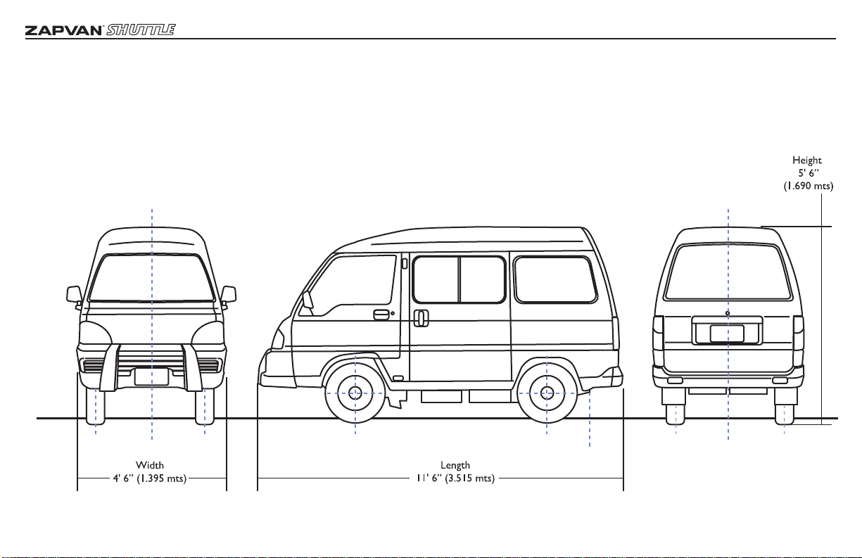
1. Overall dimensions............................................4
2.Table of performance, structure
and specication for entire truck..................5
3. Vehicle marking..................................................9
Chapter 2
Safety and Important Notes
1. Non-permissible to ret..................................9
2. Inspection of new vehicle................................9
3. Vehicle maintenance..........................................9
4. Vehicle load......................................................10
5. Inspection of tire and tire pressure............10
6. Usage of lubricants and uid for
vehicle................................................................10
7. Proper usage of safety belt...........................10
Chapter 3
Introduction of Devices
and Control Mechanism
1. Position of switches and
control levers in the cabin.............................11
2. Keys, doors and windows..............................17
3. Seats...................................................................18
4. Back gate and side gates of truck bed ........18
5. Safety belts........................................................19
6. Other Devices.................................................21
Chapter 4
Driving Suggestions
1. Driving operation...................................................24
2. Normal driving suggestions .................................24
3. Economical driving suggestions ..........................25
4. Suggestion on slippery road driving...................25
5. Suggestion on parking brake................................25
Chapter 5
Emergency Conditions
1.Vehicle refuses to start..........................................26
2. Vehicle stops running.............................................26
3. Braking trouble.......................................................26
4. Steering trouble......................................................26
5. Light changing..........................................................26
6. Deated tires..........................................................27
7. Emergency towing..................................................29
8. Anchoring.................................................................29
Chapter 6
Service and Maintenance
1. Cleaning and maintenance....................................30
2. Routine maintenance.............................................31
3. Regular maintenance..............................................31
4. Requirement for regular maintenance..............34
Chapter 7
Solutions for Malfunctions
1. Rear axle malfunction..............................................38
2. Steering, suspension, wheel and tire....................39
3. Braking malfunctions...............................................44
4. Malfunctions of power system..............................46
5. Malfunctions of on-board charger........................46
6. Malfunctions of electric controlling system.......47
7.Malfunctions of lights, instruments,
switches and indicating lights.................................48
Chapter 8
Oil Fluid forVehicle
And Electric Theory Fig
of Complete Vehicle
1. Specication and capacity of lubricant,
lubricant grease and braking uid.........................54
2. Electric Theory Fig of Complete Vehicle............54
ZAP Registration Card...................................55

2010 Owner and Operator’s Manual
4
General Information
1. Overall Dimensions

2010 Owner and Operator’s Manual
5
General Information
1. Table of performance, structure and specications for entire vehicle
1.1 Table of Dimension and Mass parameters :
Item ZAPVAN Shuttle
Type at head 4×2 driving with rear wheels
4 seats
Dimension parameters
Overall size
Length 138.4”
Width 54.9”
Height 66.5”
Wheel base 79.1”
Wheel track Front wheel 47.8”
Rear Wheel 46.9”
Mass parameters lb
Complete vehicle kerb mass 1039
Kerb axle mass Front 496
Rear 543
Full load mass 1360
Full load axle mass Front 636
Rear 724
carrying capacity 4 persons [150 lb ] and
108 lb (49 kg) loading

2010 Owner and Operator’s Manual
6
General Information
1.2 Table of performance parameters
1.3 Table of Structure and Specications
Item ZAPVAN Shuttle
Trafcability
parameters
Minimum turn radius 177.2”
Ground clearance 6”
Approach angle°30
Departure angle° 25
Front overhang 30.7”
Rear overhang 28”
Steering parameter
(what is the
measurement?)
Camber angle°2±15´
Kingpin inclination° 13
Kingpin caster° 3±1
Toe-in 2±7
Maximum
turning angle
Of wheel
Inside wheel° 34
Outside wheel° 31
Main parameters
Maximum speed MPH 25
Maximum climbing capability° 8
Max.Travel Distance 40 (miles)
Max. slope-parking capacity° (No-load)20
Item ZAPVAN Shuttle
Suspension Front suspension Coil spring Macpherson independent suspension
Rear suspension Leaf spring non-independent suspension
Steering type Pinion & rack
Braking Service brake Dual-circuit hydraulic braking system front disc and rear drum
brakes
Parking brake Mechanical cable type

2010 Owner and Operator’s Manual
7
General Information
1.3 Table of Structure and Specications (cont’d)
Item ZAPVAN Shuttle
Wheel
Type of tires Meridian tire
Tire specication 155 R12 LT 6PR
wheel rim 4.5B×12
Tire pressure
(COLD)
Front Kpa(PSI) No-load: 200 Kpa (31 PSI)
Full-load: 200 Kpa (31 PSI)
Rear Kpa(PSI) No-load: 200 Kpa (31 PSI)
Full-load: 270Kpa (39.1 PSI)
body ve doors with full metal
Electromotor Rated voltage (v) 72
Rated power ( kw) 6
Electromotor controller Rated voltage (v) 72
Rated electric current (A) 85
Auxiliary storage battery 12 V 36 Ah(C20), cathode ground strap connection
Power storage battery 72V 115Ah(C5)
DC/DC Converter
Input voltage (v) 72
Output voltage (v) 13.5
Max output electric current(A) 25
Charger (AC/DC)
input voltage (v) 90-260 (AC)
Max input electric current (A) 12
Max charging time (h) 12
Safety control system the rated electric current of fuse cutout( A) 300
the rated electric current of contactor( A) 100

2010 Owner and Operator’s Manual
8
Item ZAPVAN Shuttle
Low pressure electrical
equipment
The connection type of wire cathode ground strap connection
Rated voltage of circuit 12V
Battery 12V/36 Ah
Hoot ≥93dB (the position of 2m distance)
Washer intermittent washing and wiping with motor
Wiper Motor auto-return, intermittent and two-speed (no-load 45times/
min, 70time/min)
Lighting system
Head light 60w/55w
Front position light/front
width indicator light 5w
turn signal light 21w for front left, front right, rear left and rear left, 5w for side
front fog light 55w
brake lamp/ rear position
light 21w/5w
backup light 21w
license plate light 10w
interior light 5w
instrument panel light,
indicator light 3.4w
turn signal light ashing frequency 85±12times/min
alarming signal light ashing frequency
General Information
1.3 Table of Structure and Specications (cont’d)

2010 Owner and Operator’s Manual
9
General Information
3.Vehicle Marking
Safety and Important Notes
1. (VIN) Vehicle
Identication
Number
VIN is printed on
the lower frame of
driver’s seat in the cab,
the upper left of the
instrument panel and
on the nameplate.
2.Vehicle Nameplate
The nameplate, which is marked with Vehicle
Identication Number (VIN) is riveted on the left
B-pillar inside cab . See gure below.
3. Branding
Body surface has the ZAP logo in font and back.
ZAPVAN and Zero Emissions are also branded
on the sides.
Safety and Important Notes
WARNING!
Avoid any dangerous operation such as sudden
start and acceleration, sudden steering as the
vehicle could go out of control, roll over or
become damaged.
Avoid driving on extremely rough roads.
All passengers must wear safety belts when
the vehicle is in operation.
Do not overload the vehicle.
Vehicle circuit runs on high voltage. Use
proper procedures to avoid serious injury.
Please disconnect the battery before
performing maintenance.
1. Modication
WARNING!
Vehicle modication is absolutely prohibited
as it may impair the vehicle’s performance,
life, safety provisions and may even be
illegal by state law. Vehicle damage and
personal injury and death caused by vehicle
modication is not within the scope of the
limited warranty.
2. Inspection of New Vehicle
Owners should inspect the following items after
taking delivery of the new vehicle in order to
ensure its safety provisions and reliability:
•Check all xings of the vehicle,
especially safety parts such as steering
nut, braking and wheel nuts, etc.
•Check to see if there is any air or water leaks.
•Check oil level of gear box and rear
axle.
•Check uid level of battery.
•Check tire pressure.
•After turning on, check to see if all
instruments are functioning properly.
•When performing service, make sure
the foot and parking brakes are working
properly.
•Check that steering mechanism is
functioning normally.
•Check the driveline for abnormal noise.

2010 Owner and Operator’s Manual
10
3. Vehicle Maintenance
In order to maintain the vehicle in good running
condition, please service the vehicle according to
this manual.
4.Vehicle Load
The maximum vehicle load is specied by the
manufacturer, the maximum vehicle load capacity
is GVM (Gross Vehicle Mass). See Chapter 1,
General Information, for details. Overloading is
dangerous and may void warranty. The load of new
vehicle should not exceed 660 pounds in the rst
three months.
5. Inspection of Tires andTire Pressure
WARNING!
Improper tread depth, under or over tire
pressure could result in explosion and/or an
accident.
Tire pressure should comply with the specications
contained in the following table. Additionally,
tire pressure should be checked at least twice
monthly.
Tire pressure (Cold conditions) kPa (PSI)
Item No-Load Full-Load
Front
200Kpa
(31 PSI)
200Kpa
(31 PSI)
Rear
200Kpa
(31 PSI)
270Kpa
(39.1 PSI)
6. Usage of Oil and Fluid for vehicle
Use the lubricants and uid for the vehicle according
to the specied interval and specication. Failure
to do so may result in damage and even cause an
accident.
7. Proper Usage of the Safety Belt
For safety, seat belts for all passengers should be
worn when the vehicle is in operation.

2010 Owner and Operator’s Manual
11
Introduction of Devices and Control Mechanism
1. Switches and Control Levers in the Cabin
1
2
3
3
4
56
7
8
9
10
11
12
13
1. Combination switch (for turn signal
lights, headlights and dimmer)
2. Combination instrument panel
3.Wiper and washer switches
4. Odometer
5.Turn signal switch
6. Multifunctional display
7. Brake pedal
8.Accelerator
9. Parking brake
10. Radio
11.Ash tray
12. Glove box
13 . Ignition switch

2010 Owner and Operator’s Manual
12
Introduction of Devices and Control Mechanism
1. Ignition switch and steering lock
The ignition switch has four positions:
LOCK
It is the normal parking position when the key can
be pulled out. After removal, , the steering column
is locked.
Insert the key and turn to another position
clockwise to unlock the steering column. If it is
hard to turn the key, turn the steering wheel left
and right while turning the key.
ACC
The radio and other accessories are powered
on when turning the key to this position. But,
the electrical power of the van’s motor is not
switched on.
ON
When the key is turned to this position, all
electrical power systems of the vehicle are
switched on and the engine is ready to start.
START
When the key is turned to this position, the motor
starts. Release the key, it will return to position
“ON” automatically.
WARNING!
•Never pull out the key while the vehicle
is running. Otherwise, the steering column
will be locked up and the vehicle may go out
of control.
•In order to avoid an accident, never leave
the key in an unattended vehicle especially
when children are present.
2. Combination switch Light switch
Turn the handle to activate the lights, There are
four control positions.
OFF Position: All lights off
Position: Position light, license plate light
and IP light are on.
Position: Position light and head lights are on.
Position: Outer parking light is on.
As shown in the picture, when turning the switch
clockwise, the right turn signal light is on; In
reverse, the left turn signal light is on. (The ignition
switch must be in “ON” position.)
Dimmer switch (when switching high and low
beams)
With the headlights on, depress the control lever
to switch to high beam, lift it up to switch to
low beam. When the high beam is on, one of the
indicating lights on the combination instrument
panel will be switched on.
Lift the control lever up gently again to switch
head lights to high beam which signals your
intention to pass a vehicle ahead of you. After
releasing the control lever, the high beam will
switch to low beam.
3.Windshield Wiper Switch
When the ignition switch is in “ON” or “ACC”
position, turn the switch to “INT”, “LO” or “HI”
position to make the windshield wiper operate in
intermittent, low speed or high speed operating
state respectively.

2010 Owner and Operator’s Manual
13
Introduction of Devices and Control Mechanism
NOTE!
-In winter,before using the windshield wiper,
make sure the blade is not frozen/stuck.
Trying to operate the mechanism in this
condition may cause the windshield wiper
motor to fail.
-If the windshield wiper stops because of ice
or snow snow build, or other reasons while
running,the wiper motor can burn out even
though the windshield wiper is switched
off. At this time it is necessary to stop the
vehicle,turn off the ignition switch and clean
the windshield to ensure that the wiper can
work normally.
-Windshield wiper should not be used when
the windshield is dry,because it may scratch the
glass or damage the windshield wiper itself.
3.Windshield Washer
Lift the switch toward the direction of the arrow
and cleaning uid will spray on the windshield.
Do not use the washer continuously for over 20
seconds and it can not be used when the uid
reservoir is empty.
4. Hazard warning light switch
The red push button on the combination switch
under the steering wheel is the hazard warning light
switch. When pushed in, front, rear and side lights (six
in total) will ash. This indicates the vehicle is parked
for repair or stopped /driving abnormally for other
reasons and calls
attention to oher
drivers’ attention.
Use of the ashers
should not exceed
more than one hour
to prevent severe
battery drain.
5. Direction select switch
There are three positions of the direction al
select switch, all of which can change the driving
direction by switching.
The “F” means forward and the “R” means reverse
while the “N” means neutral.
NOTE
When starting the vehicle,the direction choice
switch must be turned to “N” position.
WARNING!
While the vehicle is moving DO NOT,
change this switch; only change this switch
after the vehicle is stopped.

2010 Owner and Operator’s Manual
14
8. High beam Indicator light
The indicator light is on when high
beam lights are activated.
9.Auxiliary battery charge light - Red
This warning light turns on when
voltage of Auxiliary battery is
below 11.8V and ignition switch is
in “ON” position.
4. Left turn Indicator light
The light ashes when turning left.
5. Speedometer
This indicates vehicle speed in mph.
6. Right turn Indicator light
The light is ashes when turning right.
7. Overload warning light
This warning light turns on when the main
power motor senses heavy use over a period
of time indicative of potential overloading.
Introduction of Devices and Control Mechanism
4. Combination instrument
1. Low Voltage indicator light
When the voltage of the power battery
is below 60V, the light is on.
2. Parking Brake warning light
This red light turns on when the ignition
switch is On and the parking brake is
activated.
3. Brake uid warning light
When brake uid is low, this warning
light turns on. If this occurs, rell brake
uid to the nominal line of uid tank
before driving to prevent brake failure.

2010 Owner and Operator’s Manual
15
Introduction of Devices and Control Mechanism
5. Multi-functional display
1. Screen
2. Display mode Selection button
3. Charge indicator /failure light
Screen
After briey displaying electric power status, the
display automatically shifts to what was selected
last time.
Format and content of the display: Electric power:
two digits, for example: 08 means 80% of the
remainder electric power.
Power battery voltage: two digits + U, for example:
75U means that current power battery voltage is
75 volts.
Power battery current: two digits + A, for example:
135A means that the on-line power battery
discharge current is 135 ampere.
Auxiliary battery voltage: two digits + P + one
digit, for example: 13P5 means that Auxiliary
battery voltage is 13.5 volts at present
Electric power combination battery: Two digits
from 01 to 10 without units ,where 10 means the
electric power remaining is 100% while 01 means
10% is remaining.
Assistant battery warning: two digits +P+ and the
unit is volts.
Display of failure code: When there is a vehicle
malfunction, the failure code display will emit
three warning beeps, and then display partial
failure information such as E-XX.
When there is tow or more concurrent types
of warnings, the multifunction display will emit a
continuous warning sound alternately with the
display code.
Code Denition
E-02 IGBT malfunction
E-03 motor over-current
E-04 control circuit under voltage
E-05 Temperature of radiator over 75℃
E-06 battery under voltage
E-07 overspeed
E-08 overload of temperature sensitive relay
E-09 * logical check of switch
E10 pedal brake warning
E-11 contactor problems
E-12 ** contactor failure
E-13 battery over voltage
E-14 parking brake warning
The specic explanation of partial failure code:
E-09*: Logical checking of switch: If shift “R” and
shift “F” have the same signal at the same time
due to the failure of direction select switch
during driving, the electric control system will
output nothing and export the failure code on
multifunction display. Turn the ignition switch to
“OFF” position and check the direction select
switch and the connecting circuit, and then restart
the vehicle .The failure disappears.

2010 Owner and Operator’s Manual
16
Introduction of Devices and Control Mechanism
E-12** Contactor failure If direction select switch
is in shift “R” or shift “F” when starting vehicle ,
electric control system has nothing to export but
failure code. Turn the ignition switch to shift “OFF”
and then turn the direction select switch to shift
“N”. Restart vehicle and the failure disappears.
NOTE
When there is vehicle, failure, the LCD
screen of the multi-function display
will show the failure code and current
information alternately.
Display mode Selection button
When the ignition switch is in position “ON”,
pressing the button will switch the display mode
as follows:
electric power Error! Not a valid link.
power battery voltage Error! Not a valid link.
power battery current Error! Not a valid link.
Auxiliary battery voltage Error! Not a valid link.
The display mode advances every time you press
this button.
Charge indicator light
When the power battery requires charging, the
light will be on intermittantly or constantly. When
battery power is down to 02, multi-function display
will periodically beep, and the charge indicator
light will be on as well At this time, you should
charge the power battery.
When the current battery power is down to 01,
the multi-function display will beep loudly and the
charge indicator light will be turned on constantly.
At this time, you must charge the power battery
immediately.
NOTE
When battery power is down to 01, charge
the battery at once, otherwise, permanent
damage may result.
5. Odometer
1. Screen
2. Selection switch
Screen
1. Distance shown on display is in miles.
2. After turning on, the screen shows the last
mileage after clearing.
3. Format and content of display:
Accumulation of all mileage:three digits with one
decimal fraction up to 999.9.For example, 234.5
means that the mileage is 234.5 miles. When the
daily mileage is larger than 999.9, the odometer
will reset automatically and add up again.
Select Switch
1. When the ignition switch is in position “ON”,
press the select switch to display mileage and
reset. If pressed for three seconds, the odometer
will reset and add up the mileage again.
2. When the ignition switch is in position “OFF”,
press and hold the select switch down and turn
the ignition switch to position “ON” at same time.
at this time, the odometer will show four low bits
and two high bits of accumulated total mileage
alternately. For example, the odometer shows the
3205, and then shows 06, it means that the total
mileage of the vehicle is 63205 miles.
3. Under the mode showing total mileage, only
when the ignition switch is turned to “ON” again
after turning to position “OFF”, the odometer will
change the mode to show current mileage.

2010 Owner and Operator’s Manual
17
Introduction of Devices and Control Mechanism
1234
5678 9 10
11
12
1. Power/volume
Switch on the electric power and adjust volume.
2. Balance adjustment knob
Adjust left/right channel for preference
3.Tone knob
Adjust for treble and bass tones
4. Screen
Displays current operating status.
5.Tuning knob
Turn to select stations
6. Band selection
7. Stereo
8. Clock/Frequency
9. Exterior Audio Converter
10. Interior Audio Jack
11. Hour
12. Minute
2. Keys , doors and windows
Keys
Each vehicle is equipped with
two identical keys which unlock
all doors and compartments.
NOTE
-It is recommended that one key be kept in a
safe place other than the vehicle.
-The key must not be removed from the
ignition switch while driving
•Never leave the key in an unattended vehicle.
Outside the door (as shown in Figure 1)
Unlocking—Turn the key clockwise
Locking—Turn the key counterclockwise
Open the door—pull the handle outwards
Close the door—Pushing the door properly
Inside the door (as shown in Figure 2)
to unlock—lift up door bolt A
To lock—Press door bolt A down
Open the door—lift Handle E up
Close the door—pull the Door Handle B
Locking the door without key
Open the door and press the door bolt down
at the lower edge of the door window. tThen lift
the outside door handle up and the door will be
locked after closing the door.
NOTE
Do not lock the door when the key is in
the vehicle.
Opening and closing windows
(as shown in Figure 2)
1. Turn the handle clockwise and counter-
clockwise to make the window go up or down
(manual window operation).

2010 Owner and Operator’s Manual
18
Introduction of Devices and Control Mechanism
3. Seats
Front seats
The angle adjuster, mounted on the outer side of
the seats, is used for adjusting the seat-back angle.
After lifting up the adjuster handle, push the seat-
back backward until the suitable position obtained
and then release the handle.
The method of moving the seat forward or
backward is as the arrows show below. To move
forward or backward lift the adjusting handle up
under the seat and then release it. If the motor
needs maintenance, please lift the entire seat up. 1. Lift up the angle adjuster handle as per below
picture to fold seats forward.
2. Draw the seat buckle up as the arrow in the
above picture to unfasten the shackle from hook.
3.Turn the seat over.
Mid-row seats
There are two seats in the mid row. The use
methods are as below:
1.Adjustment of the seat-back.
After lifting up the angle adjuster handle, push the
seat-back backward until it is in a suitable position
and then release the handle to adjust the seat-back.
2. Folding the seat down
Lift up the angle adjuster handle on the outer
side of the seats. Then loosen the rear anchor
buttery bolt or pull the locking handle when
seatback contacts the cushion. After this, you can
fold the seat down.
3.Adjustment of headrest
Loosen the buckle under headrest and adjust the

2010 Owner and Operator’s Manual
19
4. Safety belt
This Van is equipped with three-point Emergency
Locking Retractor (hereafter called ELR) safety
belt and two-point type safety belt.
1. Three-point ELR type safety belt.
Fasten the safety belt
Pull out the belt from retractor and place the
shoulder belt across the shoulder and the waist
belt across the pelvis. Then, insert the dead bolt
into the belt fastener. A “clicking” sound indicates
that the safety belt is buckled
Adjust the seat and sitting posture until it is
comfortable, and fasten the waist belt above
thighs (under the pelvis). Do not fasten it around
the abdomen. Fasten the shoulder belt to the
shoulder, but do not let it slide to arm. The
tightness of the shoulder belt may be adjusted
automatically as needed. When sudden stopping or
impact happens, the belt will lock up automatically
to protect passengers.
Loose the safety belt
With one hand holding the dead bolt, the other
hand presses the red button of belt fastener, then
the dead bolt will be bounced out to unlock the
safety belt. Allow the belt to retract slowly so as
to prevent twisting.
NOTE
After inserting the dead bolt into the belt
fastener, ensure that they are connected
rmly and the belt is not twisted. In this
case, the safety belt is buckled properly.
Adjust the safety belt
Introduction of Devices and Control Mechanism
Table of contents
Other Zap Automobile manuals
Popular Automobile manuals by other brands

Mitsubishi MOTORS
Mitsubishi MOTORS Lancer Evolution 2008 Body repair manual

Fiat
Fiat Bravo Dualogic 2009 Supplement manual

Mercedes-Benz
Mercedes-Benz Sprinter 2019 operating instructions

Mazda
Mazda 2003 Miata MX-5 owner's manual

Genesis
Genesis GV80 2021 Product reference guide

Mercury
Mercury 2006 Mountaineer owner's guide