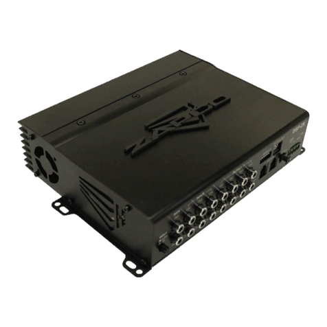
zapco HDSP-V Series User manual

Before operating the unit, please read this manual thoroughly and retain it for future reference.
Last update November 8, 2019
HDSP-V AD-A (DCP v.2.9.2)
Owner’s Manual

MISSION STATEMENT
Committed to Excellence
ZAP O is dedicated to the pursuit of audio fidelity. Our prime objectives are to
design and manufacture audio products of unsurpassed quality, to provide
unparalleled support and service for these products and to conduct business
in a manner that will enhance the quality of life for all involved.
Experience
(Knowledge from doing)
There is absolutely no substitute for experience; that is a simple fact of life.
Another simple fact is that ZAP O has, for over forty years, been the leader in
defining quality standards for the car audio industry.
These years of experience have led to a thorough understanding of the challenges
that are unique to the world of car audio. ZAP O's relentless quest for sonic purity
consistently yields imaginative designs that utilize the most innovative technologies.
The resulting products set the criteria by which all others in the industry are judged.

Table of Contents
Introduction
....................................................................................................................................................................................................... 4
The revolutionary Zapco HDSP-V Series .................................................................................................................... 4
Bar raising numbers for the Zapco HDSP-V ............................................................................................................. 5
Upgradable internal modules/components ........................................................................................................... 7
HDSP-V PAD-A Input End
........................................................................................................................................................................... 8
HDSP-V PAD-A Output End and Dash Board
............................................................................................................................... 9
HDSP-V PAD-A Cover Plate
.................................................................................................................................................................... 10
Installing the Control Program (GUI)
............................................................................................................................................. 11
Unit Installation
............................................................................................................................................................................................ 13
12V onnections .................................................................................................................................................................... 13
Input Sensitivity for Radio/ D Head Unit ............................................................................................................... 14
Opening the Control Program (GUI)
............................................................................................................................................... 15
The HDSP-Z16 V Control Program
................................................................................................................................................... 17
The Main Page .......................................................................................................................................................................... 17
The I/O Page .............................................................................................................................................................................. 22
Defining Outputs ............................................................................................................................................. 22
Defining Inputs ................................................................................................................................................. 23
Auto-Summing ................................................................................................................................................. 25
The Delay Page ........................................................................................................................................................................ 26
The rossover Page ............................................................................................................................................................... 28
The Phase Page ........................................................................................................................................................................ 30
The VSEQ Page ......................................................................................................................................................................... 32
The Equalizer ............................................................................................................................................................................. 33
Speaker Polarity and Phasing
............................................................................................................................................................. 36
Tuning - The Simple Rules
....................................................................................................................................................................... 37
Dash Board Control
.................................................................................................................................................................................... 39
Formatting Larger USB Thumb Drives/Sticks
.......................................................................................................................... 42
HD Player Quick Start
............................................................................................................................................................................... 43
Special Features of the HDSP-Z16 V Processor
........................................................................................................................ 43
Ambient Rear Fill .................................................................................................................................................................... 43
reating a Pair of 60-Band Equalizer hannels .................................................................................................... 45
Firmware Update
......................................................................................................................................................................................... 47
Technical Specifications
.......................................................................................................................................................................... 49
3

The revolutionary Zapco HDSP-V Series
From Italy finally comes a masterpiece of engineering that will mark the history of Zapco with a
fundamental step from the analog to the digital world, with everything at the highest levels possible
today in the high-end audio world. It was made for the car, but the performances are so extraordinary
that it's a unique product to use even at home as it can hold up to comparison with home audio
products, which have significantly higher prices.
The new HDSP-V is finally available in its 16 and 8 channel versions. Long-awaited, it has required an
incredibly long work for the development of firmware, software, and hardware. Six Master Engineers
have worked for 3 years on this project with over 15,000 hours of activity. It has been developed for
performance that will set entirely new standards. The noise floor of this device reaches -140 dB (noise
plane without input signal). In the 192 KHz version with player or with digital inputs, the S/N of the
analog outputs is equal to 115 dB in the basic version, or over 130 dB with the DA A option.
The HDSP-V has only one chipset that integrates two processors that work up to 64 bits and 456 MHz
(for a total of 912 MHz), both for the management of the Player and the DSP. The Player is therefore
completely integrated into the DSP itself. This guarantees the Player a total absence of connection
problems and the transmission of the signal, from the Player's processor to the DSP's processor, within
the same chipset. All up to 192 KHz for a signal line that can reach the new digital Z-AP amplifiers (coming
next year) through an optical SPDIF connection.
The possibilities of connection of the HDSP-V are with its dash remote control or with Wi-fi connection.
HD Bluetooth streaming is possible thanks to the optional module.
Vincenzo Biasella
President
APEX & Zapco
4

Bar raising numbers for the Zapco HDSP-V
The HDSP-V is the best hardware that Zapco has ever built, and the numbers attest to that. Although
the HDSP is composed of 18 individual pieces (HDSP-Z16V) put together in a modular version that is
easy to adapt or update according to your needs, the background noise and the crosstalk numbers are
superb. The end result surpassed even the expectations of the designers and engineers who built it.
The numbers are the proof of the design, for example
-140 dB of background noise
and
-115 dB of
crosstalk
. For a 16-channel device, crosstalk at -115 dB (average around 1 KHz) is proof of the accuracy
with which the layout was made. The digital inputs have 114 dB of A weighted signal/noise and the
analog inputs have 109 dB at rated output. We kept the output voltage at 4 Volts to avoid added
distortion of analog preamplification. Distortion of analog and digital inputs are lower than 0.001% at
4 Volt output and lower than 0.00175% at 1 Volt output. The HDSP-V power supply continues to work
down to 6 Volts to solve the problem of cars that have the stop-start ignition system.
The main processor is a dual core 456 + 456 MHz, 8 and16 channels solution have a 192 and 96 KHz
sampling rate and the converters are new 32 bit/784 KHz devices from AKM. Very importantly, it is an
HD Player that works at 24 bit/192 KHz integrated with DSP. There is no connection between the Player
and the DSP, no P B, no connectors, no cables. Player and DSP are integrated in one dual core chipset
that has a total power of 912 MHz. Then there is a microprocessor that controls only the Player and does
not have to do other heavy computational work like can happen, for example, with a computer. The
player has a dedicated browser that starts to work immediately when you insert the USB memory stick.
It can read all formats up to 24 bit/192 KHz, compressed or not compressed, and from the 3” touch
screen display, you can control all the functions using 3 different levels of folders. The dash board that
controls the Player also controls minor DSP functions and can manage up to 10 tuning presets with
instantaneous switching of one to another for A/B comparison.
5

All-in-one Dual Core Processor - Why a Player with on-board DSP?
Players (portable or not), often have a DSP inside, either simple or sofisticated, but it is a DSP. Zapco has
been inspired by this to offer its customers a professional DSP with the Player inside. What are the
advantagesof our integrated solution compared to that of connecting a Player to the DSP? First, it must
be said that not all portable players have a digital output. If analog, even if it’s of excellent quality, it
would always result in a degradation of quality due to the presence of two more converters on the
signal path. Therefore a coupling of an external player to an analogue input is strongly inadvisable. If,
on the otherhand, the external player has a digital output, then the situation is much better, but still
there is the limit of an SPDIF connection. The SPDIF protocol has a maximum resolution of 24 bits and
a maximum sampling rate of 192 KHz. Another limitation of the SPDIF connection is that the receiver
does not control the speed of data, so it is possible to have connection problems. In any case, the
maximum integration of the two products, DSP and Player inside the same chipset, protects from any
issues of connection whatever the nature of the problem may be.
High-End Solution: 18 independent PCB - Why odular?
The modularity of the apparatus offers considerable advantages. The first advantage is that the customer
can request the product with the cards that he needs without having to buy what he does not need.
Subsequently it is possible to easily up-grade a part of the product keeping all the rest unaltered. This
allows to keep the value of the product higher over time. The 16-channel HDSP-V is composed of 18
boards and the 8-channel HDSP-V of 15.
96 KHz (16 ch) and 192 KHz (8 ch) - What is the Sampling Rate?
The Sampling Rate represents the capacity of the digital signal to reproduce the analog signal more
faithfully. The higher it is, the better it is, but the difficulty in processing the signal increases proportionally
as well as the power of the processors used. 44 KHz is the sampling rate of a D disc. The DSPs are
normally at 48 KHz. 96 Khz and 192 KHz are the sampling rates of the most sophisticated DSPs. With
192 KHz sampling rate it is possible to have a 192 KHz digital signal line, starting from the Player up to
the amplifiers.
Very accurate Phase Filter
The HDSP-V has a very accurate All Pass filter for phase adjustment. It is possible to fix the working
frequency of the filter as accurate as 1 Hz and the phase shift also as fine as 1 degree.
VSEQ Filter
This is another innovation of the HDSP-V. Zapco has already introduced this function some time ago in the
analogue ASP-OE8 and ASP-OE2 processors. This allows to restore the response on the low frequencies of
the OEM systems as it is altered by the original manufacturers in order to protect their weak speakers
or other weaknesses when the volume of the radio is increased above a certain level.
6

7
DAC odule
hanging a DA board is a streightforward swap. One screw holds each module in its socket. You simply
remove all power to the HDSP, remove the top cover and top plate, remove the screw, and gently lift
the board out starting with the side that was screwed down. Installation is just the opposite.
Note: This is a delicate piece of electronics and parts must be lined up correctly. If you have any concerns at all,
please see your Zapco dealer for assistance.
pgradable internal modules/components
Zapco thinks to provide a perfect line of signal path to the speakers and through the listening area.
For that reason, hardware and software will be easily up-gradable with different modules that can be
changed later as the situation requires. In building the HDSP-V digital processors, we used the very best
components we could find for a production product. But knowing that there would be high-end users
out there with their personal favorite AD s or DA s, we programmed the HDSP chips to accept
different components to provide the more fanatic audiophiles the ability to easily customize the units
to their personal tastes.
ain Board
Screw

HDSP-V AD-A Input End
1.
Three
i2S (Z.CO )
allow for digital input expansion such as HD Digital Bluetooth Module (optional).
2. Coaxial Digital Input
.
3. Toslink Digital Input
.
4.
There are up to 8 hannels of input,
Differentially Balanced RCA
s, or High Level speaker inputs, for
main input. For maximum sound quality the HDSP units have analog level controls for the inputs tied
to LED clip lights. This allows you to get the maximum unclipped (clean) signal for the HDSP to work
with. Of the 8 R A input channels two (In7 and In8) can be used for an Auxiliary R A input if not all
eight inputs are needed for the main in.
5.
Below each R A input pair, there is a pair of
Speaker Level Inputs
, if you are adding the HDSP to an OEM
factory stereo you will use these connectors to take the input from the factory stereo system’s speaker
leads. The wires of each of the four plugs are labeled for correct hookup.
While your head unit may have up to 8 channels of output, we highly recommend that you use only a single full range
pair of inputs to the HDSP since the HDSP processing will be far superior to your head unit processing. Also using two
different processing stations will greatly complicate the tuning process and add distortion.
The OEM input plugs allow up to 8 channels of speaker level input, but you need only connect enough
speaker wires to get a full range signal for the HDSP to work with. Once you have wired the OEM plug the
HDSP can sum all the signals together into a full range R/L signal pair as input for all the output channels.
As noted above Input Channels 7 and 8 can be used as additional Low Level audio source. You can switch from Main
input to Auxiliary input using the G I on the PC or by choosing the LINE on the dash remote.
6. PC USB
: This USB-B receptacle can be used to connect the HDSP processor to a P for system setup.
7. WiFi odule
: This DIN receptacle will accept the Zapco Wireless Dongle for wireless connection to a
P for system adjustments.
8. Audio USB
: The USB-A receptacle accepts FAT 32 formatted USB sticks (up to 2 TB) for up to 24
Bit/192 KHz, HD Music files for the on-board Hi Definition Audio Player.
9. Dash Board
: The RG onnector accepts the connection to the Wired Remote.
10. LED Indicators
for power and protection.
1 2 3 4
6
7910 85
8

HDSP-V AD-A Output End and Dash Board
1.
The Output end is very straight forward with eight (HDSP-Z16V AD-16A) or four (HDSP-Z16V AD-8A)
pairs of Zapco’s proprietary Gold
RCA Output
connectors.
2.
The
1A Power Fuse
.
3.
The processor’s
Electrical Connections
. Below is the wire harness with the wire colors.
1 2 3
Switched ACC +12V
Turn-on +12V from Head Unit
Ground
Empty
+12V Trigger Output (Amp turn-on)
ain +12V from Battery
Power On/Off and Volume Knob
Long press to turn ON or turn OFF
the HDSP. A quick push puts the sys-
tem in MUTE. Tap again to Un-Mute.
9
HDSP-Z16 V AD-8A HDSP-Z16 V AD-16A

HDSP-V AD-A Cover Plate
There is a cover plate in the top of the HDSP processors held in place by screws. Under that plate are
the main input controls.
1.
Each channel pair has a switch to choose
ain (RCA Level)
or
OE (Speaker Level)
for the main
analog inputs.
2.
Above the level switches are the
Input Gain Controls
. Each channel has its own gain control.
3. Clipping Indicator
to adjust gain for the maximum clean (unclipped) signal.
Digital is fast, digital is convenient, but Digital is also limited. Adding gain to a signal after it is already in the digital
domain is convenient, but it will use valuable memory resources and it will increase the noise of the system and reduce
the signal's dynamic range. The HDSP processors were designed to be the best sounding digital processors... period.
To that end we used custom designed high precision analog pots to adjust the input signal to the HDSP.
Also, on the HDSP top plate are screens to assist in connecting the outputs and inputs.
10
1 2 3

Installing the Control Program (G I)
The HDSP-V Zapco processors are controlled by a P using the Zapco Digital ontrol Program.
The program is available for download on the Zapco website:
zapco.com/hdsp-5-support
Inside the HDSP-V support page you will find user’s manual, software and firmware download and
update options. lick
DCP Software v.2.9.2 (Windows PC)
under ontrol Program.
The version number will be the most current version.The program is designed to work on all Windows
systems from XP to W-10. After downloading the program, you will find this file in your Downloads
folder. Open the .exe file and the installation will begin.
The first screen gives permission to install the program. You will want to click Yes. To avoid any installation
issues you should close any other programs you have running and then click Next. By default the program
files will be stored in the HDSP-V folder. Here you can assign a different folder though we recommend
that you let it use the default folder and click Next.
In the next screen you can determine if you will have a desktop icon to open the program. By default
the HDSP icon will be installed on the desktop. lick Next. This is the final screen to make the installation.
lick Install to proceed. After the installation you can click Finish to close the installation.
11

12
Windows Drivers
The HDSP control program works with Windows system from XP through W-10. In the new 2.9.1 GUI
version, we added the signed certification to the driver. This is an autogenerated certification that
should be accepted by all the Windows OS from XP to 8.1. This should resolve all the compatibility
problems with Windows 7/8/8.1. Note also that is still possible that some version of Windows 7 still
show the warning during the installation of the driver due to Windows bug, but it is just a warning, and
it will work anyway. If your operative system, for whatever reason, does not recognize the processor,
then, you will need to turn off the Driver Signature Verification. Here is a method to do that:
Open Advanced Boot Options. Hold down the Shift key and click Restart to get Advanced Options.
hoose Troubleshoot then choose Advanced Options, and lick Startup Settings.
lick Restart to enter startup screen.
Press 7 or F7 to disable driver dignature enforcement.
Then press Enter and you will restart without driver
signature enforcement.
If you want to turn enforcement back on after you
load the drivers, you can do that the same way.

nit Installation
The first step in the installation of your processor is to disconnect the negative terminal of the battery
to prevent damage to the equipment and to the car's electrical system. The HDSP-V processor needs to
be securely mounted in a location where it will not be exposed to excessive heat, moisture, or vibration.
When choosing a location be sure there is room for all the cables and wiring that will be connected to
HDSP-V and be sure you have easy access to the USB control input to connect to the P . If you are
using the factory high level inputs from an OEM amplifier you will need to bring those connections to
the location as well. You will also want to run the cable for your dash remote, leaving plenty of extra
cable at the front until you pick a permanent location for the dash remote.
12 Volt Connections
• The
+12V Battery
wire should have a 2A fuse mounted in-line within 18 inches of the battery. If you
are connecting to a distribution block there should be a 2A fuse in-line at that connection.
• The
+12V Key
(Acc) power wire allows the HDSP to be turned when the Key is in Acc or Run positions.
• The
Ground
connection is critical to the performance of the processor. Inadequate or loose ground
connections can not only damage the processor, but they open a path for many sources of unwanted
noise. Make sure you have a good solid ground point to bare metal which is connected to the car frame.
• The
+12-Volt In for Turn-On
connects to the turn-on wire from the head unit. All aftermarket units and
many factory OEM units have these turn-on trigger wires. When available you should always use them.
•
Auto-on Sensing
: Many of the newer cars however do not have turn-on wires in the factory harness.
For these systems there is an auto-on from Audio Input switch in the GUI that activates sensors that
read signal from the speaker input wires and turn on the HDSP automatically when the factory system
is turned on.
• The
+12-Volt Output
connection is used to provide turn-on current for your amplifiers. This connection
will be active whether you use the +12 turn-on from the head unit, or you use the Auto-on system. All
amplifiers should use this source for the turn-on so the Processor can control the turn-on of the amplifiers.
NOTE: To avoid turn-on pops and other noises all amplifiers must use the turn-on output of the HDSP for their trigger
inputs. For multiple amplifiers turn on, it is safest to use a relay as below (common Bosch Style Automotive Relay).
After the +12 Volt and Ground connections are completed you can finalize all the other connections
at the HDSP except the R A signal cables to the amplifiers. These should not be connected to the
HDSP until after the input levels and default crossovers are set. This will avoid damage to the speakers
during gain setting.
From DSP turn-on output
From Car Battery
To all amplifiers turn-on wires
To Ground
13

At this point you should have:
• Secure power and ground connections to all system components with fuses at each component and
a fuse or fuses at the main feed close to the battery.
• The main input at either the R A or Spk level input connected, and the input switches are set accordingly.
• Any Auxiliary input cables (R A or Digital) are run and connected.
• The dash remote cable is run and connected.
• All amplifiers cables and turn-on wires are run and connected. All the amplifier gain controls should
be set to minimum at this time but the amplifier signal cables should not be plugged into the HDSP.
You can now re-connect the negative battery terminal and prepare for system set-up.
First: Input Sensitivity for Radio/CD Head Unit
To get the best possible signal to noise ratio and the widest dynamic range, you want the HDSP to
receive the strongest undistorted signal it can accept. To aid in this, Zapco provides a gain pot and lip
LED for each channel accessed under the top cover as seen earlier in the manual. The first step is to
ensure that the Input switch is in the correct position for either MAIN (R A) or OEM (Speaker level).
heck that all tone controls are off and balance controls, and fader controls are set "0" or enter. To set
the gains you will turn the system on and watch the LEDs in the gain panel on the top of the DSP.
Remember: the amplifier RCAs are not plugged in yet, so there will be no sound. You're just watching the LEDs
To properly set the gains you want to play the most dynamic (usually the loudest) piece of music you are
likely to listen to and play it at the highest volume your head unit can play cleanly. If you are unsure about
what that volume is, you can consider that most modern head units will play cleanly to about 80% of the
volume control, so a little over 3/4 volume. With the volume at this level you can begin adjusting the gain
pots up starting with hannels 1/2. Slowly turn the gain pots up until the red LED just flashes and then
back off just slightly. The red LED tells you the signal is in the distorted area. At the final position you want
the level as high as it can be without flashing the red LED. Of course you need to adjust only those channels
you are actually using for input. Most systems with aftermarket head units will only use the inputs h1/2.
After you have set the input for the active input channels, be sure to turn the head unit volume back to minimum to
avoid bad surprises later, and then turn the system off.
Connecting the PC
Now you should connect your Laptop or P to the HDSP with the supplied USB cable. Then you can
open the Digital ontrol Program and familiarize yourself with the different GUI pages.
14

Opening the Control Program (G I)
When you click on the Zapco HDSP Heatsink icon you get the splash screen below. Notice the GUI version
number (here it is v.2.9.1) on the right side under DIGITAL ONTROL PROGRAM.
The HDSP Series is an evolving product and any number of features will be added as new technologies
become available. You will want to keep a regular eye out for updates at
zapco.com/hdsp-5-support
to
keep your HDSP current.
Before the GUI opens, you need to tell the program if you wish to open in
Connect via WIFI*
or
Connect via CO **
mode and which HDSP model you will be working with Select Device drop-down
menu. If you choose onnect via OM mode you will confirm the OM port number and you can click
START to open the GUI.
* Your HDSP processor can be controlled by P or laptop through either the supplied USB connection or
by wireless connection. The initial connection must be by USB, then once the GUI is opened you can
enable the WiFi for future connections (see pag. 17 to enable WiFi).
** Different P s can react differently to USB cables. If the supplied 5m cable does not allow immediate
connection (no OM port showed under Select OM, you should try a 2m USB cable.
15

16
If you have already used the GUI and you have previously saved some configurations, you can choose
which configuration to upload between Last Saved, Default, hoose from P , or hoose from DSP Preset.

The HDSP-Z16 V Control Program
The HDSP graphic user interface (GUI) currently consists of a Main page and 5 function pages.
The function pages allow a user to set all the channels for a particular function at the same time. The
Main page then is an at-a-glance review of the settings and allows fine tuning adjustments that may
be needed during the equalization stage.
1. Speaker Channel Assignments:
This section shows the function of each output channel and is
where you will choose a channel for fine tuning. The information here is transferred in from the I/O
page where the assignments are made.
2. Crossover Section
: This shows the crossover choices of each output channel. As you assign functions
on the I/O page, default crossovers will be assigned to protect speakers. In the rossover section you
can modify the crossovers to match the needs of your particular speakers.
12 3 4 5
6
17

3. Delay and Polarity
: Signal delay allows you to adjust the arrival time of each channel so that it will
sound as though you are dead center in the car, even though you are likely sitting far to one side or the
other. All speakers in a system must be “in phase” for tuning to be effective. This means they must be of
the same polarity (all moving the same direction at the same time). If a speaker is out of phase with the
rest of the system you can change its polarity in the GUI to the right of the delay adjustments.
4. ute/Solo
: These buttons allow you to listen to individual speakers or groups of speakers, as needed
during fine tuning. If you Right lick on any channel’s mute button you have the option to Mute All or
Unmute All.
5. Output Level
: Here you can adjust for any channels whose output level is not as needed for the
correct overall sound.
6. Equalizer
: This is the section where you will do the fine tuning. We will discuss more about equalizing
later in the system setup. The Equalizer is on the Main page, so you can have all your other settings
handy for fine adjustments as needed during the equalization procedure.
The Navigation Bar
At the top of the Main page is the navigation bar. On the right side the navigation bar are the links to
the function pages. At the left side you will find the FILE menu and the LOAD/SAVE menu.
FILE enu
: The file holds the seseveral functions below.
WiFi anagement
: Your HDSP processor can be controlled by P or laptop through either the supplied
USB connection or by wireless connection. The initial connection must be by USB, then once the GUI is
opened you can enable the WiFi for future connections (be sure to connect the WiFi dongle at the
round Mini DIN WiFi port on the processors input side).
ZapcoA P is your access point. The default password is 12345678. You can change the password by
highlighting the current password and clicking SET.
18

Power ON/OFF anagement
- The On/Off function of electrical components cause pulses that can be
amplified by the system’s amplifier and cause “POP” noises. The HDSP firmware and software are designed
to prevent this. The Power On/Off menu lets you modify the On /Off delays to best suit your system’s
needs. From the factory, the HDSP will turn on with only power and ground by pushing the Volume
knob of the Dashboard remote. One of the first things you should do is what system you will use for
On/Off triggers. A couple of notes are needed for Power by Audio in and for the timing of the amplifier
turn-on from the HDSP. For the Power On/Off by Audio In you will want a short delay for On, but a long
delay for Off. The lower section is to control the amplifier turn-on from the White +12v out. Power off
delays are normally not used because you want the amp to turn off fast so it cannot amplify the turn-off
pulse. This is often a problem because most processors that have turn-on wires must turn off before
the amp trigger can turn off. The HDSP lets you set a delay for the amp turn-on and delay, or no delay,
for amp turn-off. The third setting (Off Power Enable Delay) lets you set a delay time that keeps the
HDSP on until after the amp has had time to shut off completely so there will be no turn-off noise.
Reset
- Allows you to undo changes you have made to the system. You can choose to return to the
default settings of the desired parameter or you can simply return to the last saved value to undo only
the last adjustment.
19

OE Automix
: Most new vehicles have information/warning systems operating through the factory
stereo system. Since the HDSP has a considerable number of input choices beyond the factory stereo
we have included the OEM Auto-Mix function so your information system will work regardless of your
music source. Given that there are many differences in signal level in different vehicles, the OEM Auto-mix
function lets you determine the threshold of the signal to be allowed to mix into the music and the
volume of the information signal in relation to the music signal.
Logout
: Logout will save close the GUI screen and return you to the opening splash screen.
LOAD/SAVE enu
: You can load or save to a file on your computer or to one of the 10 presets in the
HDSP-V.
To PC File
- The HDSP program installed a folder on your P specifically for storing and retrieving
preset configurations. When you choose Save to P file you will be taken to the Preset 16 h or Preset
8 h folder. The System will apply a name for the configuration which will be highlighted when the folder
opens. You can choose to keep that name, but it is recommended that you assign your own name. ie
Rock Tune, ompetition Tune, etc. The name of the current preset will always show in the navigation
bar next to the LOAD/SAVE icon.
To Device
- Saving to Device puts the preset configuration into one
of the HDSP’s on-board memory positions. As with the P file, you will assign a preset number and be
asked to assign a name to the preset.
Navigation Bar (or Traffic) Lights
At the right side of the Navigation bar you will see the function buttons that can be lit green, yellow, or
red. You can change the color of these lights as needed. These green, red, and yellow lights have been
added to be used as reminders to help assure that your system setup is complete. Just like traffic lights,
green indicates that a process is completed, and you can continue on, yellow means you may need to
check on the function before moving on, and red means something definitely needs to be done before
proceeding.
20
This manual suits for next models
1
Table of contents
Other zapco Signal Processor manuals
Popular Signal Processor manuals by other brands

Boss Audio Systems
Boss Audio Systems CPBK3.5 user manual

Rosendahl
Rosendahl nanoclocks GL instruction manual

Extron electronics
Extron electronics MGP 641 xi Series user guide

Kurzweil
Kurzweil KSP8 MLAN IO OPTION - REV B Reference

BBE
BBE Sonic Maximizer 882i User guide and reference manual

turck
turck MS96-11EX0-R/230VAC quick start guide