34
Summarize
T7AH-2400 is a style of RC equipments that can be used for fixed wing aircraft also
can be used for helicopters model aircraft.It use the 2.4 GHz frequency-hopping
spread spectrum radio system, tell the replacement of the remote control
equipment crystal trouble,you won't have to worry about interference cause by the
remote control equipment of the same frequency. This type of remote control also
can restassured be used in large oil power plane,because the receiver of it can
resist almost all of electromagnetic interference in the air.
The transmitter main performance indicators
Work power: 8 nimh battery charge section
Working current: <
Launch frequency: 2400 MHz (FHSS)
Channel number: 7
Function set instructions way: LCD
Receiver main performance indicators
Work power: 4.8 V-6
Receive frequency: 2400 MHz
Channel number: 7 + PPM signal channel
Second, Characteristics
●7 channel steering gear had function
●With the helicopter and fixed wing two kind of control mode and free switch when
starting up.
●A memory of various models' parameter settings of 8 kinds of fixed wings and 8
kinds of helicopters flight respective.
●Wireless simulator funtion can be used to directly output simulator's signal to
computer.
●Wireless trainer function can prevent the user from the trouble connecting the
trainer line.
●The way of receiving code can easily finish matching between transmitter and
receiver.
●A transmitter can match with more than one of receivers's codes.
●Transmitters can work at same time without any special set. They wouldn't be
interfered with each other.
●The receiver's antenna horizontal polarization and vertical polarization double
receive complementary system
Three, the machine configuration
A T7AH-2400 transmitter
A R7AH-2400 a receiver
Four pcs DJ 200 servo
Transmitter battery
Receiver battery
Special charger
Four, the binding transmitter and receiver
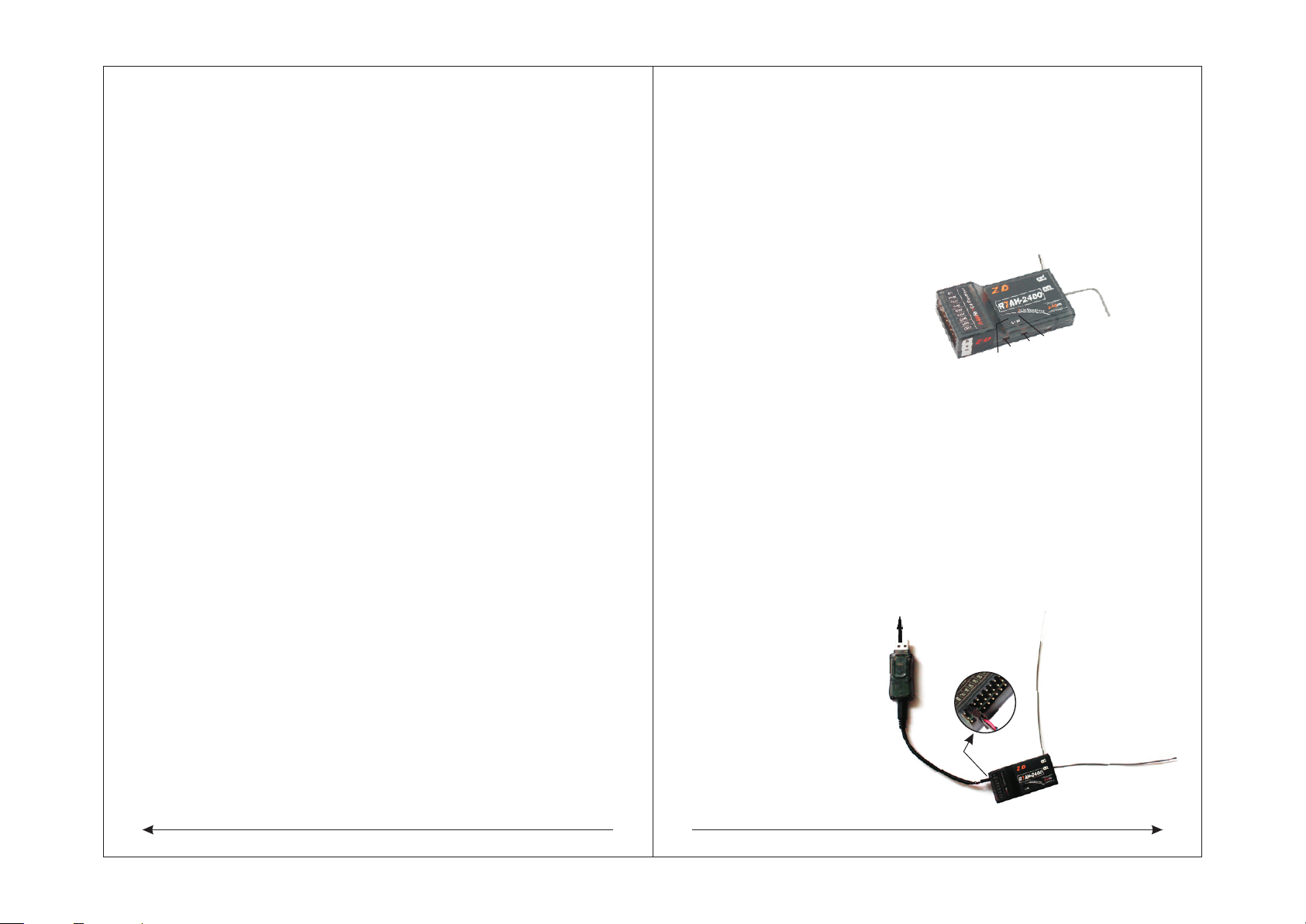
◆the code of thehost and receiver
he transmitter can and two different receiver supporting the use of the R7AH
-2400 and R7AH-2400 A. The type 2400 have antenna with Double channel
receiver function. the vertical and horizon plate form are more sensitive,
and with wireless trainer function Function of code as follows:.
◆Using receiver with trainer fuction to code
R7AH 2400 receiver with wirless trainer function can use any transmitter as trainer,
another one transmitter as student machine. Student machine should code with the
trainer R7AH 2400 receiver , then the students transmitter can be used. The method
is shut down power of the trainer, while open the student transmitter's and connect
with receiver transmitter power, press the S-code switch untill the green S-LED
indication go solid
Note: There couldn't have other 7 TAH-2400 in the receiver's received signal range
when coding, or not success
Five, R7AH-2400 wireless simulator function
Connecting a computer USB outlet
The second
plug-in of pins
from the
front view
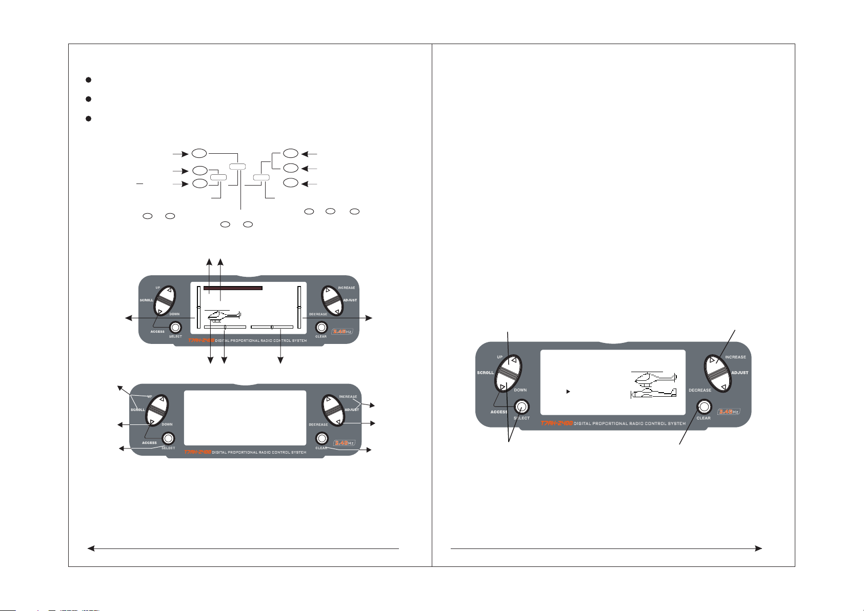
Six, control stick tension adjustment
◆Remoting the screws of the back of the RC
R7AH-2400 PPM channel can use special set of plugs line connection with
simulator decoder. Then insert the decoder into the computer USB mouth, use
transmitter can complete wireless simulator function.
Connect transmitter and receiver's power, firstly, press the M code switch of
receiver till the M-LED indicator light changes from flickering into lighting. Then,
press the S code switch till the S-LED indicator light changes from flickering into
lighting, shows that transmitter and receiver code success.
The model 2400 A is single received channel with wireless trainer function,
only one code switch and a indicator light, the way to code is same with
2400 type, only coding the single yards.
Note: There couldn't have other 7 TAH-2400 in the receiver's received signal range
when coding, or not success.
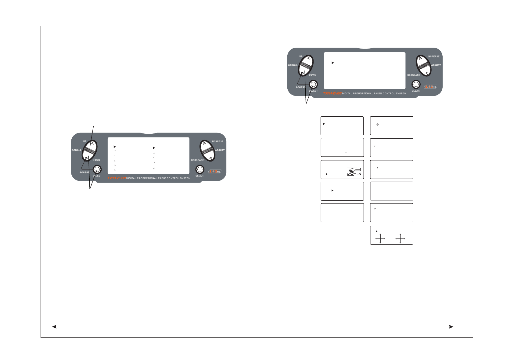
S-LED indicator light
Scode switch
Mcode switch
M-LED indicator light