ZENEC Z-E7015S User manual

PORSCHE
Z- E 7 0 15 S
INSTALLATIONSANLEITUNG
DEVICE INSTALLATION MANUAL

Bitte Beachten / Please Note
➜ Eine einwandfreie Funktion des Gerätes kann nur
dann gewährleistet werden, wenn Sie das im Lieferumfang
enthaltene Zubehör verwenden.
➜ Am beiliegenden originalen Hauptanschlusskabel dürfen
keine Veränderungen irgendwelcher Art vorgenommen
werden.
➜ Achten Sie bei der Installation darauf, dass die
verschiedenen Anschlusskabel und Zubehörteile nicht
durch scharfe Kanten beschädigt oder geknickt werden.
Verwenden Sie keine Gewalt während der Montage.
➜ Die im Text in Klammern stehenden Nummern (No.x) sind
den im Lieferumfang befindlichen Zubehörteilen zugeordnet.
Beachten Sie zur besseren Identifikation die Packliste mit
den entsprechenden Abbildungen.
➜ Achten Sie vor der finalen Montage des Gerätes darauf,
dass alle Steckverbindungen auf der Geräterückseite richtig
verbunden und fest eingerastet sind.
➜ Aktualisierungen der Gerätesoftware des Gerätes
werden mit einem USB-Datenträger installiert.
Das Gerät muss während der Montage mit dem im
Lieferumfang enthaltenen USB-Hub bestückt werden,
um zukünftige Software Updates zu gewährleisten.
➜ Bei Fahrzeugen mit dem originalen Navigationssystem
PCM 2.1. und integrierter SOS-Taste muss die externe Box
für die Freisprecheinrichtung stillgelegt werden.
➜ Achten Sie bei Fahrzeugen mit Lichtwellenleitertechnik
darauf, dass die Kabel nicht zu sehr gebogen oder geknickt
werden. Bei Nichtbeachtung kann eine Beschädigung des
Kabels resultieren.
➜ Bei Fragen oder Problemen wenden Sie sich an Ihren
ZENEC-Händler, bei dem Sie das Gerät gekauft haben.
➜ The flawless function of the device can only
be guaranteed, when the original accessories and wire
harnesses contained in the set are deployed as described in
this installation manual.
➜ Do not apply any modifications on the original wire
harness of device and vehicle.
➜ During device installation, pay proper attention not to
damage any of the wires, plugs or other parts. Avoid
applying excessive mechanical force especially when
pushing the unit back into the slot.
➜ There are numbers inside the parentheses (No.x), which
are dedicated to the accessories, contained in the scope of
delivery. For a better identification, please pay attention to
the packing list with the corresponding drawings.
➜ Please check if all plug-and-socket connections on the
rear of the device are properly seated before you insert
and fix the device in the console.
➜ MainSystem software updates of the device are
installed via a USB flash memory device.
The device thus requires fitting of the USB hub which is
included in delivery, to sustain future software updates.
➜ For vehicles with the original navigation system PCM 2.1
and integrated SOS button, the external hands-free box has
to be shut down.
➜ If your vehicle is equipped with fibre optic cable technol-
ogy, pay proper attention not to bend the wires too much.
Non-observance may damage the cables.
➜ Please contact your authorized ZENEC dealer or the
distributor of the country, where you have purchased your
E>GO unit, if you have any technical problems or further
questions.
Das Fahrzeug ist mit einem Eigen-
diagnosegerät (DME) ausgestattet.
Um Fehlermeldungen und Fehlfunk-
tionen (z.B. Antennensystem) zu ver-
meiden, muss vor Beginn der Montage
unbedingt der negative Pol der Fahr-
zeugbatterie abgehängt werden.
Montage / Installation This vehicle is equipped with a DME
system featuring self-diagnosis. To avoid
error codes in the DME and malfunctions
(e.g. antenna system), the GND wire
of the negative battery pole must be
disconnected before any wiring or instal-
lation work is started.
1
Entfernen Sie die sich hinter den
Seitenabdeckungen befindlichen Torx-
schrauben (TX25).
Remove the torx screws (TX25) behind
the side covers.
2
2
Entfernen Sie jeweils die Torxschraube
(TX20), um die hinteren Seitenabdeckun-
gen im Fussraum der Fahrer- und Beifah-
rerseite zu demontieren.
Remove the torx screws (TX20) to disas-
semble the rear side covers on the floor
of the driver and passenger side.
3
3
You can now remove the panels on both
sides of the center console.
Sie können nun die Verkleidungen auf
beiden Seiten der Mittelkonsole ent-
fernen.
4
4

Entriegeln Sie mit einem Imbusschlüssel
(M5) das Originalradio aus den beiden
Halteklammern auf der Fahrerseite. Dre-
hen Sie dazu den Imbusschlüssel um 90
Grad nach unten.
Lösen Sie mit einem Gabelschlüssel
(M7) die auf dem Bild markierte Schrau-
be bis sich das Originalgerät aus der
Halterung entfernen lässt.
Unlock the original radio out of the two
holding clamps on the driver side by us-
ing an Allen key (M5). Turn the Allen key
by 90 degrees so it points out.
66
77
Carefully remove the original radio out of
the radio mounting slot.
Ziehen Sie das Originalgerät vorsichtig
aus dem Radioschacht.
88
Entriegeln Sie vorsichtig die Stecker an
der Rückseite des Originalgerätes.
99Unplug all connectors on the backside
of the original radio.
If your vehicle is equipped with a BOSE
active sound system, please use the
MOST adapter (No.13), which is included
in the scope of delivery.
Connect the plug of the on-board fibre
optic cable with the MOST adapter.
Connect the detachable cable with the
pre-amplifier outputs (No.4), which is
included in the scope of delivery, and
connect it with the ZENEC device.
Next, connect the FR and FL plugs
with the FR and FL plugs of the MOST
adapter.
Entriegeln Sie mit einem Imbusschlüssel
(M5) das Originalradio aus den Halte-
klammern auf der Beifahrerseite. Drehen
Sie dazu den Imbusschlüssel um 90
Grad nach unten.
Unlock the original radio out of the two
holding clamps on the passenger side by
using an Allen key (M5). Turn the Allen
key by 90 degrees so it points out.
55
Falls Ihr Fahrzeug mit einem BOSE
Sound System ausgerüstet ist, verwen-
den Sie den im Lieferumfang enthaltenen
MOST Adapter (No.13).
Verbinden Sie den Stecker des fahrzeug-
seitigen Lichtwellenleiterkabels mit dem
MOST Adapter.
Nehmen Sie nun das im Lieferumfang
enthaltene steckbare Anschlusskabel mit
den Vorverstärkerausgängen (No.4) und
verbinden Sie es mit dem ZENEC Gerät.
Die Anschlüsse FR und FL des An-
schlusskabels müssen anschliessend mit
den FR und FL Anschlüssen des MOST
Adapters verbunden werden.
10 10
Release the screw marked in the left pic-
ture, by using an open-end wrench (M7)
until it is possible to remove the original
radio out of the mounting slot.

Route the extension cord of the USB hub
(No.4) from the radio mounting slot to
the required place of installation (with-
out illustration).
Verbinden Sie das Hauptanschlusskabel
mit dem ZENEC CAN-Bus Interface
(No.12).
Verwenden Sie den im Lieferumfang
enthaltenen Antennenadapter (No.8),
um das ZENEC Gerät (No.1) an die Fahr-
zeugantenne anzuschliessen.
Montieren Sie die GPS-Antenne (No.2)
an einer geeigneten Stelle und achten
Sie darauf, dass der GPS-Empfang nicht
durch die Abschattung von metallischen
Fahrzeugteilen negativ beeinflusst wird
(Wärmeschutzverglasung etc.).
Empfehlenswerte Montageorte
für die GPS-Antenne ist auf dem
metallischen Tragerahmen auf der
Beifahrerseite(ohne Abb.).
Verlegen Sie das Verlängerungskabel
des USB-Hubs (No.4) vom Radioschacht
an den von Ihnen gewünschte Montage-
ort (ohne Abb.).
Falls Sie das mitgelieferte externe
Bluetooth Mikrofon (No.6) verwenden
möchten, montieren Sie es jetzt und
verlegen das Anschlusskabel ebenfalls
in den Radioschacht.
Empfehlenswerte Montageorte für das
Bluetooth Mikrofon sind in der Nähe
des Rückspiegels bzw. der Innenraum-
leuchte.
Je nach Präferenz und Wahl des gerätein-
ternen oder externen Mikrofons, muss
im „Setup Menü“ die Mikrofonquelle für
den Bluetooth Modus entsprechend an-
gepasst werden (ohne Abb.).
12 12
13
14
15
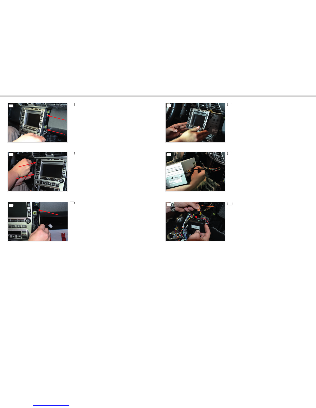
11 Connect the main wire harness with the
ZENEC CAN bus interface (No.12).
Use the antenna adapter (No.8), which
is included in the scope of delivery, to
connect the ZENEC device (No.1) to the
vehicle antenna.
Mount the GPS receiver (No.2) at a
suitable location and make sure that the
GPS reception isn’t adversely affected by
shadowing effects of car parts made of
metal (heat-insulating glass etc.).
A recommendable place of installation
for the GPS antenna is at the metal spar
on the passenger side (without illustra-
tion).
If you want to use the included, external
Bluetooth microphone (No.6), mount it
now and route the connection cable to
the radio mounting slot as well.
Recommendable places of installation
for the Bluetooth microphone are close
to the rear view mirror or the car interior
lighting.
Depending on the preference and selec-
tion of the device internal or external (to
be installed) microphone, the BT micro-
phone source must be chosen correctly
in the setup menu (without illustration).
Verbinden Sie alle zuvor in den Radio-
schacht verlegte Kabel mit dem ZENEC
Gerät.
Schieben Sie anschließend das ZENEC
Gerät vorsichtig zurück in den Radio-
schacht.
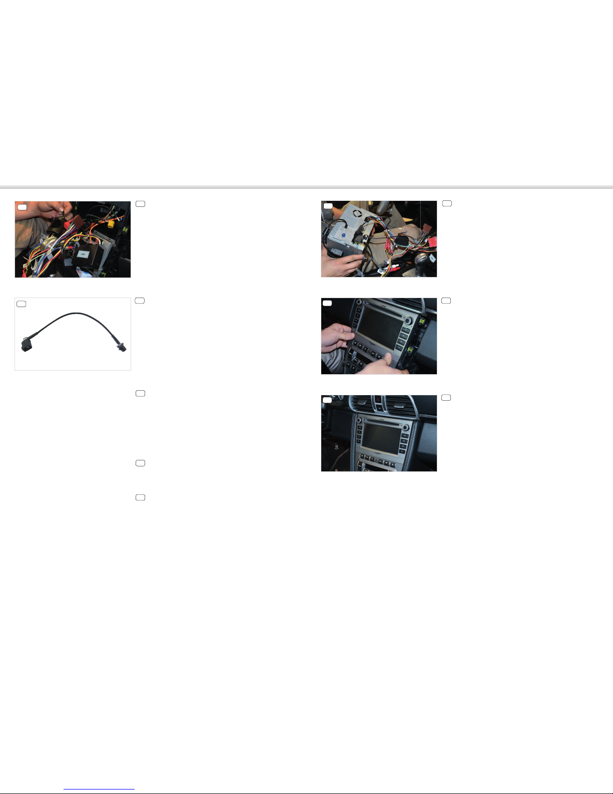
16 16 Connect all cables, which were routed
to the radio mounting slot before, to the
ZENEC device.
Carefully slide the ZENEC device into the
radio mounting slot.
Für die Endmontage folgen Sie den An-
weisungen ab Punkt 3 in umgekehrter
Reihenfolge.
17 17 For the final assembly, please follow step
three in reverse order.
Stellen Sie sicher, dass sich das Fahr-
zeug im Freien befindet und der GPS
Empfang nicht durch irgendwelche
Abschattungen (Bäume, hohe Gebäude
etc.) negativ beeinflusst wird.
Stecken Sie die mitgelieferte SD-Karte
(No.11) mit der Navigationssoftware in
den dafür vorgesehenen SD-Kartenslot
des ZENEC Gerätes und starten Sie es
anschließend, um den sogenannten
Sat-Fix zu erstellen.
Achten Sie darauf, dass das Fahrzeug
nicht bewegt wird, bis der Sat-Fix er-
stellt ist. Drücken Sie nun die NAV-Taste,
um den Navigationsmodus zu starten
und wählen Sie Kartenansicht aus.
Sobald in der Kartenansicht Ihr aktu-
eller Standort zu sehen ist, wurde der
Sat-Fix automatisch erstellt, was je
nachdem 3 bis 5 Minuten dauern kann.
Sie können das ZENEC Gerät jetzt ver-
wenden.
Führen Sie abschliessend einen all-
gemeinen Funktionstest durch und
nehmen Sie die Grundeinstellungen
vor. Stellen Sie zudem sicher, dass
fahrzeugseitig keine Fehlermeldungen
erscheinen.
18 Make sure that the vehicle is outdoors
under free sky and that GPS reception
isn’t impaired by shadowing effects
(trees, tall buildings etc.).
Insert the provided SD card which con-
tains the navigation software into the
respective SD card (No.11) slot of the
ZENEC device and turn on the device
allowing it to create a Sat-Fix.
The vehicle should not be moved until
the Sat-Fix has completed. Now press
the NAV button to start the navigation
mode and choose the map screen.
Once your current position is visible
on the map, the Sat-Fix has been suc-
cessfully created (which may take 3 to
5 minutes). You can use your ZENEC
device now.
You should carry out a general function
test and adjust all basic settings. Make
sure that the vehicle does not produce
any error messages.
18
11

Anschlussdiagramm / Device Connection Diagram
Packliste / Packing list
NO. ITEM SKETCH MAP QUANTITY
1
Grundgerät
1
Main unit
2
Externe GPS-Antenne
1
External GPS antenna
3
Hauptanschlusskabel
1
Main wire harness
4
USB-Hub mit Kabel
1
USB hub with cable
5
DVB-T/DAB
Anschlusskabel 1
DVB-T/DAB
connection cable
6
Externes BT
Mikrofon 1
External BT
microphone
7
BT Mikrofon
Adapterkabel 1
BT microphone
interface
8
Antennenadapter
1
Antenna adapter
9
Steckbare
Anschlusskabel 3
Detachable cables
8
GND
B+
ACC
RCA FR
RCA FL
C
D
Use only for
Bose®Sound Systems
Druckfehler und technische Änderungen vorbehalten. Subject to technical changes and misprints.
Stand Dezember 2014 · Rev. A
ZENEC · Bohrturmweg 1 · CH-5330 Bad Zurzach · Schweiz/Switzerland · E-Mail: support@zenec.com · www.zenec.com
TOUCH ANOTHER WORLD
10
Fernbedienungen
1
Remote control
11
SD Karte 8 GB
1
SD card 8 GB
12
ZENEC CAN-Bus Interface
1
ZENEC CAN bus interface
13
MOST Adapter
1
MOST adapter
14
Diebstahlschutzaufkleber
1
Anti-theft label
15
Bedienungsanleitung
4
Device user manual
16
Installationsanleitung
1
Device installation manual
17
Anschlussdiagramm
1
Device connection diagram
18
Nav Schnellstartanleitung
2
Nav quick start guide
Popular Car Stereo System manuals by other brands

Blaupunkt
Blaupunkt Hamburg CD70 installation instructions

JEHNERT SOUND DESIGN
JEHNERT SOUND DESIGN 75075 installation instructions

Alfa Romeo
Alfa Romeo 4C Alpine Radio 2018 manual

Kenwood
Kenwood EZ500 - Radio / CD instruction manual

Clarion
Clarion DXZ758RMC installation manual

MNC
MNC OVERDRIVE user manual