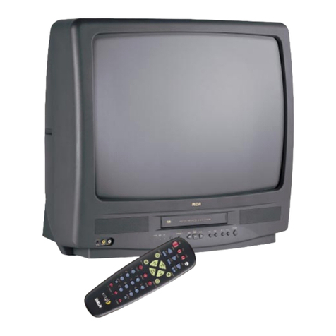
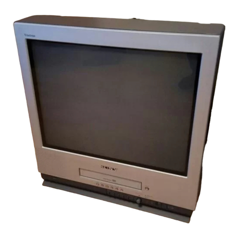
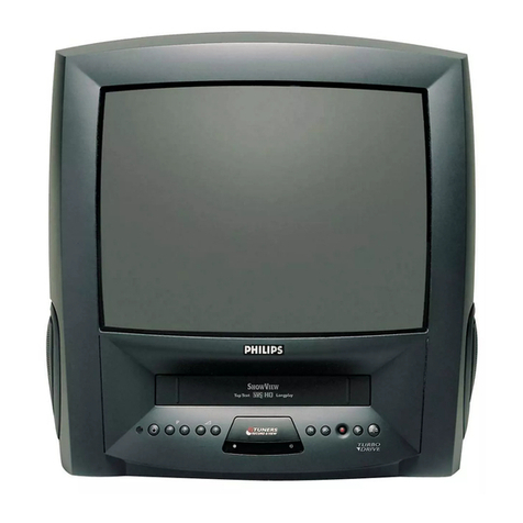
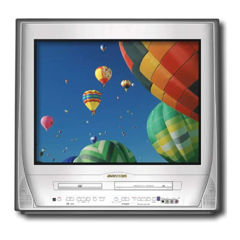
Zenith TVBR1342Z User manual

SERVICE MANUAL
Product Type: Color TV /VCR Combo
Chassis: CC-002
Manual Series: CM152
Manual Part #: 923-03440
Model Line: C
Product Year: 2000
PublishedbyTechnicalPublications
Zenith Electronics Corporation
201 James Record Road - Huntsville, Alabama 35824-1513
May 2000
Printed in U.S.A.
CN DG 5k
Model Series:
TVBR1342Z
CONTENTS
General Information ......................................1
Servicing.....................................................2
Parts ..........................................................3
Exploded views.............................................4
Schematics ..................................................5
TVBR1942Z
TVBR2542Z

IMPORTANT SAFETY NOTICE
This manual was prepared for use only by properly trained audio-visual service
technicians.
When servicing this product, under no circumstances should the original
design be modified or altered without permission from Zenith Electronics
Corporation. All components should be replaced only with types identical to
those in the original circuit and their physical location, wiring and lead dress
must conform to original layout upon completion of repairs.
Special components are also used to prevent x-radiation, shock and fire hazard.
These components are indicated by the letter “x” included in their component
designators and are required to maintain safe performance. No deviations are
allowed without prior approval by Zenith Electronics Corporation.
Circuit diagrams may occasionally differ from the actual circuit used. This way,
implementation of the latest safety and performance improvement changes into
the set is not delayed until the new service literature is printed.
Caution: Do not attempt to modify this product in any way. Never perform
customized installations without manufacturer’s approval. Unauthorized
modifications will not only void the warranty, but may lead to property damage
or user injury.
Service work should be performed only after you are thoroughly familiar with
these safety checks and servicing guidelines.
Graphic symbols
The exclamation point within an equilateral triangle is intended
to alert the service personnel to important safety information in
the service literature.
The lightning flash with arrowhead symbol within an equilateral
triangle is intended to alert the service personnel to the presence
of noninsulated “dangerous voltage” that may be of sufficient
magnitude to constitute a risk of electric shock.
The pictorial representation of a fuse and its rating within an
equilateral triangle is intended to convey to the service personnel
the following fuse replacement caution notice:
CAUTION: FOR CONTINUED PROTECTION AGAINST RISK OF FIRE,
REPLACE ALL FUSES WITH THE SAME TYPE AND RATING AS MARKED
NEAR EACH FUSE.
SERVICE INFORMATION
While servicing, use an isolation transformer for protection from AC line shock.
After the original service problem has been corrected, make a check of the
following:
FIRE AND SHOCK HAZARD
1. Be sure that all components are positioned to avoid a possibility of
adjacent component shorts. This is especially important on items trans-
ported to and from the repair shop.
2. Verify that all protective devices such as insulators, barriers, covers,
shields, strain reliefs, power supply cords, and other hardware have been
reinstalled per the original design. Be sure that the safety purpose of the
polarized line plug has not been defeated.
3. Soldering must be inspected to discover possible cold solder joints, solder
splashes, or sharp solder points. Be certain to remove all loose foreign
particles.
4. Check for physical evidence of damage or deterioration to parts and compo-
nents, for frayed leads or damaged insulation (including the AC cord), and
replace if necessary.
5. No lead or component should touch a receiving tube or a resistor rated at
1 watt or more. Lead tension around protruding metal surfaces must be
avoided.
6. After re-assembly of the set, always perform an AC leakage test on all exposed
metallic parts of the cabinet (the channel selector knobs, antenna terminals,
handle and screws) to be sure that set is safe to operate without danger of
electrical shock. DO NOT USE A LINE ISOLATION TRANSFORMER DURING THIS
TEST. Use an AC voltmeter having 5000 ohms per volt or more sensitivity in
the following manner: Connect a 1500 ohm, 10 watt resistor, paralleled by
a .15 mfd 150V AC type capacitor between a known good earth ground
water pipe, conduit, etc.) and the exposed metallic parts, one at a time.
Measure the AC voltage across the combination of 1500 ohm resistor and
.15 mfd capacitor. Reverse the AC plug by using a non-polarized adaptor
and repeat AC voltage measurements for each exposed metallic part. Voltage
measured must not exceed 0.75 volts RMS. This corresponds to 0.5 milliamp
AC. Any value exceeding this limit constitutes a potential shock hazard and
must be corrected immediately.
X-RADIATION
1. Be sure procedures and instructions to all service personnel cover the
subject of x-radiation. The only potential source of x-rays in current TV
receivers is the picture tube. However, this tube does not emit x-rays when
the HV is at the factory-specified level. The proper value is given in the
applicable schematic. Operation at higher voltages may cause a failure of
the picture tube or high-voltage supply and, under certain circumstances
may produce radiation in excess of desirable levels.
2. Only factory-specified CRT anode connectors must be used.
3. It is essential that the service personnel have available an accurate and
reliable high-voltage meter.
4. When the high-voltage circuitry is operating properly, there is no possibility
of an x-radiation problem. Every time a color chassis is serviced, the
brightness should be run up and down while monitoring the high voltage
with a meter, to be certain that the high voltage does not exceed the
specified value and that it is regulating correctly.
5. When troubleshooting and making test measurements in a product with a
problem of excessively high voltage, avoid being unnecessarily close to
the picture tube and the high voltage power supply. Do not operate the
product longer than necessary to locate the cause of excessive voltage.
6. Refer to HV, B+, and shutdown adjustment procedures described in the
appropriate schematics and diagrams (where used).
IMPLOSION
1. All direct view picture tubes are equipped with an integral implosion
protection system; take care to avoid damage during installation.
2. Use only the recommended factory replacement tubes.
TIPS ON PROPER INSTALLATION
1. Never install any receiver in a closed-in recess, cubbyhole, or closely
fitting shelf space over, or close to, a heat duct, or in the path of heated
air flow.
2. Avoid conditions of high humidity such as: outdoor patio installations
where dew is a factor, near steam radiators where steam leakage is a factor,
etc.
3. Avoid placement where draperies may obstruct venting. The customer
should also avoid the use of decorative scarves or other coverings that
might obstruct ventilation.
4. Wall- and shelf-mounted installations using a commercial mounting kit
must follow the factory-approved mounting instructions. A product mounted
to a shelf or platform must retain its original feet (or the equivalent
thickness in spacers) to provide adequate air flow across the bottom. Bolts
or screws used for fasteners must not touch any parts or wiring. Perform
leakage tests on customized installations.
5. Caution customers against mounting a product on a sloping shelf or in a
tilted position, unless the receiver is properly secured.
6. A product on a roll-about cart should be stable in its mounting to the cart.
Caution the customer on the hazards of trying to roll a cart with small
casters across thresholds or deep pile carpets.
7. Caution customers against using a cart or stand that has not been listed
by Underwriters Laboratories, Inc. for use with its specific model of
television receiver or generically approved for use with TVs of the same or
larger screen size.
8. Caution customers against using extension cords. Explain that a forest of
extensions, sprouting from a single outlet, can lead to disastrous
consequences to home and family.
PRODUCT SAFETY SERVICING GUIDELINES FOR AUDIO-VIDEO PRODUCTS
i
A.C. Voltmeter
1500 OHM
10 WATT
Place this probe
on each exposed
metal part.
Good Earth Ground
such as the Water
Pipe, Conduit, etc.
0.15uF

CM152 H13C01L - SAFETY
and confirm a good signal is being displayed. Reduce Brightness
and Contrast settings until the picture is well extinguished.
Observe the Anode Voltage meter reading and compare with the
table below. If the voltage reading is higher than the maximum,
verify circuit component values and proper operation.
EQUIPMENT REQUIRED
a) Video Generator
b) HV DC meter (0 to 40kv, high Z)
TEST PROCEDURE
To verify the Shutdown Circuit is working properly, proceed with the
following procedure.
1. Istall a 100K ohm variable resistor across R529.
2. Turn the unit on and set the input A.C. Voltage to 130VAC.
3. Adjust the variable resistor from maximum to minimum. During this
adjustment monitor the anode voltage to the C.R.T. this voltage
SERVICING GUIDELINES FOR X-RADIATION PROTECTION
ii
X-RAY PROTECTION CIRCUIT DESCRIPTION
If the High Voltage on Anode off (FB401) F.B.T. is increased, the
Heater voltage will increase at the same time. The voltage from
Heater is rectified by D412, and then the dc voltage is divided by
R420 and R442. At normal operation, the voltage V1 on pin 85
of IC-I1001 is 5.9V. If HV exceeds its safety level, Q1023 is
switched on, resulting in V1 loss on pin 85 this in turn causes a
lossof horizontaldrive toq405, therebyshutting downthe unit,
activating H.V. Shut Down. The X-Ray protect line also monitors
CRT ANODE HIGH VOLTAGE MEASUREMENT PROCEDURE
Each screen size has its own safe Anode Voltage and shutdown
voltage. Critical Safety Components (designated with shading in the
component parts list) are designed to operate the CRT at a safe
operating Anode voltage and provide proper shutdown thresholds.
If replacement of any of these components are deemed necessary, it
is important to use original Zenith replacement components. After
replacement is made, confirm proper Anode Voltage using the fol-
lowing procedure.
Measurement of the CRT Anode Voltage must be performed using a
high impedance high voltage meter, with no visible raster on the
screen, and operating at nominal horizontal scanning frequency.
Connect a strong broadcast signal (or TV signal generator
operating at 15.734kHz horizontal scanning rate) to the RF input.
After the CRT is discharged, connect a high impedance high
voltage meter at the distribution point. Turn the television on
SCREEN B+ VDC HV NOM HV MAX
SIZE (0 BEAM) KV KV
13 128.5+/-2% 26kv 29kv
COMPONENT LEVEL REPAIR
19
25
128.5+/-2%
128.5+/-2%
28kv
31.5kv
33kv
34kv
the B+ line via D408 which is fed by a voltage divider circuit
consisting of R441,R440 and R439.
should not exceed the maximum H.V. listed in the chart above. If
this voltage exceeds the maximum H.V. for the size C.R.T. listed,
the X-Ray protect circuit is not working properly and must be
repaired prior to returning the unit to the customer.


CM152 TOC TVBR
TABLE OF CONTENTS
SECTION 1 GENERAL INFO / REMOTE CONTROL
SPECIFICATIONS .......................................................... 1-1
SECTION 2 SERVICING
DISASSEMBLY INSTRUCTION .......................................... 2-1
REMOVAL OF MECHANICAL PARTS AND PC BOARDS........... 2-1
REMOVAL OF DECK PARTS.............................................. 2-5
REMOVAL OF ANODE CAP .............................................. 2-10
KEY ABBREVIATIONS.................................................... 2-12
SERVICE MODE............................................................ 2-14
PREVENTIVE CHECKS AND SERVICE INTERVALS ................. 2-15
NOTE FOR REPLACING OF MEMORY IC ............................. 2-17
SERVICING FIXTURES AND TOOLS ................................... 2-19
PREPARATION FOR SERVICING ........................................ 2-20
MECHANICAL ADJUSTMENTS.......................................... 2-21
ELECTRICAL ADJUSTMENTS............................................ 2-25
SECTION 3 PARTS LIST
COMPONENT PARTS LIST ............................................... 3-1
SECTION 4 EXPLODED VIEW
13/19" MECHANICAL EXPLODED VIEW ............................ 4-1
25” MECHANICAL EXPLODED VIEW ................................. 4-2
13/19" CHASSIS EXPLODED VIEW .................................. 4-3
25” CHASSIS EXPLODED VIEW ....................................... 4-4
13/19/25" UPPER DECK EXPLODED VIEW ........................ 4-5
13/19/25" LOWER DECK EXPLODED VIEW ........................ 4-5
SECTION 5 SCHEMATIC
13/19" POWER SUPPLY CIRCUIT ..................................... 5-1
13/19" Interconnect Diagram ....................................... 5-1
13/19" Main Micro Block Diagram ................................. 5-2
13/19" Audio Block Diagram ........................................ 5-3
13/19" Video Block Diagram ........................................ 5-4
25" Interconnect Diagram ............................................ 5-5
25" Main IC Block Diagram .......................................... 5-6
25" Audio IC Block Diagram ......................................... 5-7
25" Video IC Block Diagram ......................................... 5-8
13/19" Primary Power Circuit ....................................... 5-9
13/19" Deflection Circuit ............................................. 5-10
13/19" Main Microprocessor Circuit ............................... 5-11
13/19" Chroma Circuit ................................................. 5-12
13/19" Head Amp Circuit ............................................. 5-13
13/19" Audio Amp Circuit ............................................ 5-14
13/19" CRT Circuit....................................................... 5-15
13/19" Deck Circuit ..................................................... 5-16
13/19" Input/Output Circuit ......................................... 5-17
13/19" Control Panel Circuit......................................... 5-18
25" Primary Power Circuit ............................................ 5-19
25” Deflection Circuit .................................................. 5-20
25" Main Micro Circuit ................................................. 5-21
25" Chroma Circuit...................................................... 5-22
25" Head Amp Circuit .................................................. 5-23
25" Audio Amp Circuit ................................................. 5-24
25" CRT Circuit ........................................................... 5-25
25" Deck Circuit.......................................................... 5-26
25" Input/Output Circuit .............................................. 5-27
25" Control Panel Circuit.............................................. 5-28
13/19" Main PCB Top Layout ........................................ 5-29
13/19" Main PCB Bottom Layout ................................... 5-30
13/19" Control Panel & Deck PCB Layout ....................... 5-31
25" Main PCB Layout ................................................... 5-32
25" System Control PCB Top Layout ............................... 5-33


SPECIFICATIONS
(TV SECTION)
PICTURE SIZE:
13 INCH TVBR1342Z
19 INCH TVBR1942Z
25 INCH TVBR2542Z
SYSTEM: NTSC
FREQUENCY:
VHF: 2-13 ch
UHF: 14-69 ch
CATV: 14-36 (A) – (W) ch
37-59 (AA) – (WW) ch
60-85 (AAA) – (ZZZ) ch
86-94 (86) – (94) ch
95-99 (A-5) – (A-1) ch
100-125 (100) – (125) ch
01 (5A) ch
INTERMEDIATE FREQUENCY
Picture IF Carrier Frequency: 45.75 MHz
Sound IF Carrier Frequency: 41.25 MHz
SOUND INTERMEDIATE
FREQUENCY: 4.5 MHz
MAXIUM OUTPUT POWER: 1.5W (Model TVBR1342Z)
1.5W (Models TVBR1942Z)
2.5W (Models TVBR2542Z)
SPEAKER: 8 ohm (Models TVBR1342Z, TVBR1942Z)
16 ohm x 2 (Models TVBR2542Z)
POWER SOURCE: AC 120V, 60Hz (All Models)
POWER CONSUMPTI0N:70W (ModelsTVBR1342Z)
86W (Models TVBR1942Z)
120W (Models TVBR2542Z)
CM152 1-1 GENERAL INFO

SPECIFICATIONS
(VCR SECTION)
OPERATING TEMPATURE: 5°C to 40°C
STORAGE TEMPATURE: -20°C to 60°C
VIDEO RECORDING SYSTEM: VHS, 2 head rotary heads helical scanning system
Luminance: FM azimuth recording
Color Signal: Low frequency converted direct recording
HEADS:
Video: 2 Head (Models TVBR1342Z. TVBR1942Z, TVBR2542Z)
Audio/Control: 1 Stationary Head
Erase: 1 Full Track Erase
TAPE WIDTH: 12.65mm high density
AUDIO TRACK: 1 Track
F.FWD TIME: Approx. 3’40” (with T-120 cassette)
REW TIME: Approx. 2’50” (with T-120 cassette)
TAPE SPEED: SP: 33.35mm/sec
LP: 16.67mm/sec
SLP: 11.12 mm/sec
INPUT LEVEL: Video: 1.0Vp-p, 75ohm unbalanced
Audio: 300mV, 50k ohm unbalanced
OUTPUT LEVEL: Video: 1.0Vp-p, 75ohm unbalanced
Audio: 300mV, 1k ohm unbalanced
WEIGHT: 27.6 lbs. (Models TVBR1342Z)
48.7 lbs. (Models TVBR1942Z)
67.1 lbs. (Models TVBR2542Z)
DIMENSION: 14.48”(W) x 14.8”(D) x 15.28”(H) (Model TVBR1342Z)
19.56”(W) x 18.5”(D) x 19.18”(H) (Model TVBR1942Z)
24.72”(W) x 19.8”(D) x 24.2”(H) (Models TVBR2542Z)
CM152 1-2 GENERAL INFO

TVBR 13/1942Z DISASSEMBLYINSTRUCTIONS
1. REMOVAL OF MECHANICAL PARTS
AND P.C. BOARDS
1-1: BACK CABINET (Refer to Fig. 1-1)
1.
2.
3.
4.
Remove the 6 screws 1.
Remove the screw 2which is used for holding the Back
Cabinet. (2 Screws on the back of TVBR 2542Z)
Remove the AC cord from the AC cord hook 3.
Remove the Back Cabinet in the direction of arrow.
1-2: CRT PCB (Refer to Fig. 1-2)
CAUTION: BEFORE REMOVING THE ANODE CAP,
DISCHARGE ELECTRICITY BECAUSE IT
CONTAINS HIGH VOLTAGE.
BEFORE ATTEMPTING TO REMOVE OR
REPAIR ANY PCB, UNPLUG THE POWER
CORD FROM THE AC SOURCE.
1.
2.
3.
Remove the Anode Cap.
(Refer to REMOVAL OF ANODE CAP)
Disconnect the following connector: (CP801).
Remove the CRT PCB in the direction of arrow.
Fig. 1-2
Front Cabinet
1-3: VCR BLOCK (Refer to Fig. 1-3)
1.
2.
3.
4.
Fig. 1-3
Front Cabinet
CRT PCB
1
VCR Block
UP TO
RELEASE
2
Remove the 2 screws 1.
Disconnect the following connectors:
(CP757, CP353, CP401 and CP502).
Unlock the support 2.
Remove the VCR Block in the direction of arrow.
1
Fig. 1-1
1
1
12
1Back Cabinet
Front Cabinet
1
1
3
CM152 2-1 SERVICING

TVBR 13/1942Z DISASSEMBLYINSTRUCTIONS
1-5: SYSCON PCB (Refer to Fig. 1-5)
1.
2. Remove the screw 1.
Remove the Syscon PCB in the direction of arrow.
1
Syscon PCB
Fig. 1-5
Deck Holder
1-4:
1.
2.
3.
4.
5.
6.
7.
Remove the 3 screws 1.
Remove the 3 screws 2.
Remove the Deck Shield Plate in the direction of arrow (A).
Disconnect the following connectors: (CP1004, CP1005,
CP1006, CP4001, CP4002 and CP4003).
Remove the Deck Chassis in the direction of arrow (B).
Remove the screw 3.
Remove the Bottom Shield in the direction of arrow (C).
2
1
2
2
1
1
3
(C)
(B)
(A)
Bottom Shield
Fig. 1-4
Deck Shield Plate
Deck Chassis
Syscon PCB
DECK SHIELD PLATE, DECK CHASSIS AND
BOTTOM SHIELD (Refer to Fig. 1-4)
CM152 2-2 SERVICING

Front Cabinet
TVBR2542Z DISASSEMBLYINSTRUCTIONS
1. REMOVAL OF MECHANICAL PARTS
AND P.C. BOARDS
1-1: BACK CABINET (Refer to Fig. 1-1)
1.
2.
3.
Remove the 6 screws 1.
Remove the 2 screws 2which are used for holding the
Back Cabinet.
Remove the Back Cabinet in the direction of arrow.
1-3: TV/VCR BLOCK (Refer to Fig. 1-3)
1.
2.
3.
4.
Remove the 2 screws 1.
Disconnect the following connectors:
(CP303, CP401, CP502, CP4201 and CP4202).
Unlock the support 2.
Remove the TV/VCR Block in the direction of arrow.
Fig. 1-3
1-4: MAIN PCB (Refer to Fig. 1-4)
1.
2.
3.
4.
Remove the PCB Holder in the direction of arrow (A).
Remove the 3 screws 1.
Disconnect the following connectors:
(CP810 and CP820).
Remove the Main PCB in the direction of arrow (B).
2
1
Fig. 1-1
Front Cabinet
1-2: CRT PCB (Refer to Fig. 1-2)
CAUTION: BEFORE REMOVING THE ANODE CAP,
DISCHARGE ELECTRICITY BECAUSE IT
CONTAINS HIGH VOLTAGE.
BEFORE ATTEMPTING TO REMOVE OR
REPAIR ANY PCB, UNPLUG THE POWER
CORD FROM THE AC SOURCE.
1.
2.
3.
Remove the Anode Cap.
(Refer to REMOVAL OF ANODE CAP)
Disconnect the following connectors:
(CP802 and CP850).
Remove the CRT PCB in the direction of arrow.
Fig. 1-2
Back Cabinet
Front Cabinet CRT PCB
1
1
1
2
2
1
1
1
Fig. 1-4
1
UP TO
RELEASE
TV/VCR Block
Main PCB
1
PCB Holder
(A)
(B)
VCR Block
CM152 2-3 SERVICING

TVBR2542Z DISASSEMBLYINSTRUCTIONS
1-5: DECK SHIELD PLATE (Refer to Fig. 1-5)
1.
2.
3.
Remove the 2 screws 1.
Remove the screw 2.
Remove the Deck Shield Plate in the direction of arrow.
1
1
2Deck Shield Plate
VCR Block Fig. 1-5
1-6: DECK CHASSIS (Refer to Fig. 1-6)
1.
2.
3.
Remove the 3 screws 1.
Disconnect the following connectors:
(CP1004, CP1005, CP1006, CP4001, CP4002 and CP4003).
Remove the Deck Chassis in the direction of arrow.
1-7: JACK PLATE AND SYSCON PCB (Refer to Fig. 1-7)
1.
2.
3.
4.
5.
6.
7.
Remove the screw 1.
Remove the Syscon PCB in the direction of arrow (A).
Remove the 2 screw 2.
Remove the nut 3.
Remove the washer 4.
Unlock the 2 supports 5.
Remove the Jack Plate in the direction of arrow (B).
Jack Plate
Deck Holder
Syscon PCB
(A)
2
5
5
(B)
3
4
Fig. 1-7
2
1
11
1
Deck Chassis
Syscon PCB
Fig. 1-6
CM152 2-4 SERVICING

TVBR13/19/2542Z DISASSEMBLYINSTRUCTIONS
2. REMOVAL OF DECK PARTS
2-1: TOP BRACKET (Refer to Fig. 2-1)
Remove the 2 screws 1.
Slide the 2 supports 2and remove the Top Bracket.
1.
2.
NOTE
When you install the Top Bracket, install the screw (1)
first, then install the screw (2).
1
(2)
Top Bracket Top Bracket
Main Chassis
Main Chassis
2
1
(1)
2
Fig. 2-1
NOTE
When you install the Tape Guide L, install as shown in the
circle of Fig. 2-3-B. (Refer to Fig. 2-3-B)
REC Lever
Tape Guide L
• The REC Lever is not installed on the Video Cassette Player. Fig. 2-3-B
2-4: CASSETTE HOLDER ASS'Y (Refer to Fig. 2-4)
Move the Cassette Holder Ass'y to the front side.
Push the Locker R to remove the Cassette Side R.
Remove the Cassette Side L.
1.
2.
3.
Main Chassis
Main Chassis
Cassette Side L
Cassette Side R Locker R
Fig. 2-4
2-5: CASSETTE SIDE L/R (Refer to Fig. 2-5)
Unlock the 4 supports 1and then remove the Cassette
Side L/R.
1.
• Screw Torque: 5 ±0.5kgf•cm
2-2: FLAP LEVER/TAPE GUIDE R (Refer to Fig. 2-2)
NOTE
When you install the Cassette Side R, be sure to move the
Locker R after installing.
Cassette Side L
Cassette Side R
1
1
1
Locker R 1
Fig. 2-5
Move the Cassette Holder Ass'y to the back side.
Remove the Polyslider Washer 1.
Remove the Flap Lever.
Unlock the 3 supports 2and remove the Tape Guide R.
1.
2.
3.
4.
Fig. 2-2
2-3: TAPE GUIDE L (Refer to Fig. 2-3-A)
Move the Cassette Holder Ass'y to the back side.
Unlock the 2 supports 1and remove the Tape Guide L.
Remove the REC Lever. (Recorder only)
1.
2.
3.
1
Main Chassis
Tape Guide L
REC Lever
Fig. 2-3-A
• The REC Lever is not installed on the Video Cassette Player.
1
1
2
2
2
Tape Guide R
Flap Lever
Main Chassis
CM152 2-5 SERVICING

TVBR13/19/2542Z DISASSEMBLYINSTRUCTIONS
2-6: LINK ASS'Y (Refer to Fig. 2-6)
Set the Link Ass'y to the Eject position.
Remove the (A) side of the Link Ass'y first, then remove
the (B) side.
1.
2.
Main Chassis
(A)
Main Chassis
Link Ass'y
Fig. 2-6
2-7: LOADING MOTOR ASS'Y (Refer to Fig. 2-7)
Remove the Link Lever.
Remove the Dumper Spring.
Remove the 2 screws 1.
Unlock the support 2and remove the Loading Motor
Ass'y.
Unlock the 2 supports 3and remove the Deck PCB
(BOT).
1.
2.
3.
4.
5.
2-9: TENSION ASS'Y (Refer to Fig. 2-9-A)
Move the Inclined S Ass'y to the back side.
Remove the Tension Spring.
Unlock the support 1and remove the Tension Arm
Ass'y.
Remove the Tension Adjust.
Unlock the 2 supports 2and remove the Tension Band
Ass'y.
Unlock the support 3and remove the Tension Holder.
Remove the SS Brake Spring.
Remove the SS Arm Brake.
1.
2.
3.
4.
5.
6.
7.
8.
1
2
1
Loading Motor Ass'y
Link Lever
Main Chassis
ï Screw Torque: 5 ±0.5kgfïcm Fig. 2-7
2-8: SENSOR COVER L3 (Refer to Fig. 2-8)
Unlock the support 1and remove the Sensor Cover L3.1.
Deck PCB
(BOT)
Link Ass'y
(B)
Dumper Spring
3
3
1
2
2
Tension Adjust
Tension Band Ass'y
Tension Spring Tension Arm Ass'y
Tension Holder
Inclined S Ass'y
Fig. 2-9-A
SS Brake Spring
SS Arm Brake
NOTE
When you install the Tension Adjust, install as shown in
Fig. 2-9-B. (Refer to Fig. 2-9-B)
Fig. 2-9-B
2-10: T BRAKE ASS'Y (Refer to Fig. 2-10)
Remove the T Brake Spring.
Remove the T Brake Ass'y.
1.
2.
T Brake Ass'y
Fig. 2-10
Adjust the direction of the Marker to inside.
T Brake Spring
Main Chassis
Sensor Cover L3
1
Fig. 2-8
Main Chassis
Sensor Cover L3
1
TVBR13/1942Z TVBR2542Z
CM152 2-6 SERVICING

DISASSEMBLY INSTRUCTIONS
2-11: S REEL/T REEL (Refer to Fig. 2-11)
Remove the S Reel and T Reel.
Remove the 2 Polyslider Washers 1.
1.
2.
NOTE
Do not touch the Pinch Roller. (Use gloves.)
When you install the Pinch Roller Block, install as shown
in the circle of Fig. 2-12-B. (Refer to Fig. 2-12-B)
1.
2.
NOTE
Take care not to damage the gears of the S Reel and T
Reel.
The Polyslider Washer may be remain on the back of
the reel.
Take care not to damage the shaft.
Do not touch section "A" of S Reel and T Reel. (Use
gloves.) (Refer to Fig. 2-11)
When you install the reel, clean the shaft and oil it.
(If you do not oil, noise may be heard in FF/REW
mode.)
After installing the reel, adjust the height of the reel.
(Refer to MECHANICAL ADJUSTMENT)
1.
2.
3.
4.
5.
6.
S Reel
1
(A)
T Reel
(A)
1
Fig. 2-11
2-12:PINCH ROLLER BLOCK/P5-3 ARM ASS'Y
(Refer to Fig. 2-12-A)
Remove P5 Spring.
Remove screw 1.
Unlock the 2 supports 2and remove the Cassette
Opener.
Remove the Pinch Roller Block, Pinch Roller Arm
Spring, Pinch Roller Lever Ass'y and P5-3 Arm Ass'y.
1.
2.
3.
4.
1
2
2
P5 Spring
Cassette Opener
P5-3 Arm Ass'y
Pinch Roller Block
Pinch Roller Lever Ass'y
Main Chassis
Fig. 2-12-A
Pinch Roller Arm Spring
ï Screw Torque: 5 ±0.5kgfïcm
Fig. 2-12-B
2-13: A/C HEAD (Refer to Fig. 2-13-A)
Remove screw 1.
Remove the A/C Head Base.
Remove the 3 screws 2.
Remove the A/C Head and A/C Head Spring.
1.
2.
3.
4.
NOTE
Do not touch the A/C Head. (Use gloves.)
When you install the A/C Head Spring, install as shown
in Fig. 2-13-B. (Refer to Fig. 2-13-B)
When you install the A/C Head, tighten screw (1)
first, then tighten screw (2), finally tighten screw
(3).
1.
2.
3.
A/C Head
2
2
A/C Head Spring
1
(3)
(1)
2
(2)
A/C Head Base
Spring Position Fig. 2-13-B
2-14: FE HEAD (RECORDER ONLY) (Refer to Fig. 2-14)
Remove screw 1.
Remove the FE Head.
1.
2.
1
FE Head
ï The FE Head is not installed on the Video Cassette Player.
ï Screw Torque: 4 ±0.5kgfïcm
Fig. 2-13-A
ï Screw Torque: 4 ±0.5kgfïcm (Screw 1)
Fig. 2-14
CM152 2-7 SERVICING

DISASSEMBLY INSTRUCTIONS
1
2
E-Ring
Middle Gear
Main Cam
Pinch Roller Cam
Joint Gear
P5 Cam
Fig. 2-17-A
NOTE
When you install the Pinch Roller Cam, P5 Cam and Main
Cam, align each marker. (Refer to Fig. 2-17-B)
Pinch Roller Cam
P5 Cam
Main Cam
Marker
Check the hole of Main
Chassis can be seen.
Fig. 2-17-B
2-18: CLUTCH ASS'Y (Refer to Fig. 2-18)
Remove the Polyslider Washer 1.
Remove the Clutch Ass'y, Ring Spring and Coupling
Gear.
Unlock the 2 supports 2and remove the Clutch Lever.
1.
2.
3.
2-16: CAPSTAN DD UNIT (Refer to Fig. 2-16)
Remove the Capstan Belt.
Remove the 3 screws 1.
Remove the Capstan DD Unit.
1.
2.
3.
• Screw Torque: 5 ±0.5kgf•cm Fig. 2-16
2-17: MIDDLE GEAR/MAIN CAM (Refer to Fig. 2-17-A)
Remove the Polyslider Washer 1, then remove the
Middle Gear.
Remove the E-Ring, then remove the Main Cam, P5
Cam and Pinch Roller Cam.
Remove the Polyslider Washer 2, then remove the
Joint Gear.
1.
2.
3.
Capstan DD Unit
Capstan Belt
11
1
Fig. 2-18
1
Clutch Ass'y
Ring Spring
Coupling Gear
Clutch Lever
2
2
2-15: AHC ASS'Y/CYLINDER UNIT ASS'Y
(Refer to Fig. 2-15)
Unlock the support 1and remove the AHC Ass'y.
Remove the 3 screws 2.
Remove the Cylinder Unit Ass'y.
1.
2.
3.
When you install the Cylinder Unit Ass'y, tighten the
screws from (1) to (3) in order while pulling the Ass'y
toward the left front direction.
NOTE
1
AHC Ass'y
Cylinder Unit Ass'y
2
2
2
• Screw Torque: 3 ±0.5kgf•cm Fig. 2-15
(1)
(3)
(2)
CM152 2-8 SERVICING

DISASSEMBLY INSTRUCTIONS
2-19: LOADING GEAR S/T ASS'Y (Refer to Fig. 2-19-A)
1.
2.
3.
4.
5.
6.
7.
8.
9.
1
2
Capstan Brake Spring Capstan Brake Ass'y
Main Rod Main Loading Gear
Tension Lever
Loading Gear T
Loading Gear
Spring
Loading Arm T Ass'y
Loading Gear S
Loading Gear
Spring
Loading Arm S Ass'y
LED Reflecter
Idler Arm Ass'y
Clutch Actuator
Remove the E-Ring 1and remove the Main Loading
Gear.
Remove the Capstan Brake Spring.
Slide the Main Rod and remove the Capstan Brake
Ass'y.
Remove the Main Rod, Tension Lever, Clutch Actuator,
Idler Arm Ass'y.
Remove the screw 2.
Remove the LED Reflecter.
Remove the Loading Arm S Ass'y and Loading Arm T
Ass'y.
Remove the Loading Gear S and Loading Gear T.
Remove the Loading Gear Spring.
2. When you install the Clutch Actuator, install as shown in
the circle of Fig. 2-19-C. (Refer to Fig. 2-19-C)
Fig. 2-19-C
Clutch Actuator
NOTE
Do not touch the roller of Guide Roller.
Fig. 2-20
Loading Gear Holder
Inclined T
P4 Cover
Guide Roller
Inclined S
1
2
3
4
4
Guide Roller
2-20: INCLINED S/T ASS'Y (Refer to Fig. 2-20)
Unlock the support 1and remove the P4 Cover.
Remove the screw 2.
Unlock the support 3and remove the Loading Gear
Holder.
Remove the Inclined S.
Remove the Inclined T.
Remove the 2 screws 4, then remove the Guide Roller.
1.
2.
3.
4.
5.
6.
• Screw Torque: 5 ±0.5kgf•cm Fig. 2-19-A
NOTES
Loading Arm T Ass'y
Main Loading Gear
Marker
Marker
Loading Arm S Ass'y
1. When you install the Loading Arm S Ass'y, Loading Arm
T Ass'y and Main Loading Gear, align each marker.
(Refer to Fig. 2-19-B)
Fig. 2-19-B
• Screw Torque: 5 ±0.2kgf•cm (Screw 2)
• Screw Torque: 0.7 ±0.2kgf•cm (Screw 4)
CM152 2-9 SERVICING

3. REMOVAL OF ANODE CAP
After turning the power off there might still be a potential
voltage that is very dangerous. When removing the
Anode Cap, make sure to discharge the Anode Cap's
potential voltage.
Do not use pliers to loosen or tighten the Anode Cap
terminal, this may cause the spring to be damaged.
REMOVAL
1. Follow the steps as follows to discharge the Anode Cap.
(Refer to Fig. 3-1.)
Connect one end of an Alligator Clip to the metal part of
a flat-blade screwdriver and the other end to ground.
While holding the plastic part of the insulated Screwdriver,
touch the support of the Anode with the tip of the
Screwdriver.
A cracking noise will be heard as the voltage is discharged.
Flip up the sides of the Rubber Cap in the direction of the
arrow and remove one side of the support.
(Refer to Fig. 3-2.)
2.
GND on the CRT
Screwdriver
Alligator Clip
Support CRT
GND on the CRT
Rubber Cap
CRT Support Fig. 3-2
3. After one side is removed, pull in the opposite direction to
remove the other.
NOTE
Take care not to damage the Rubber Cap.
INSTALLATION
1. Clean the spot where the cap was located with a small
amount of alcohol. (Refer to Fig. 3-3.)
Location of Anode Cap
NOTE
Confirm that there is no dirt, dust, etc. at the spot where
the cap was located.
2.
3.
Arrange the wire of the Anode Cap and make sure the
wire is not twisted.
Turn the Rubber Cap over.(Refer to Fig. 3-4.)
DISASSEMBLY INSTRUCTIONS
Fig. 3-3
Fig. 3-4
*
Fig. 3-1
*
Read the following NOTED items before starting work.
CM152 2-10 SERVICING

4. Insert one end of the Anode Support into the anode button,
then the other as shown in Fig. 3-5.
5.
6. Confirm that the Support is securely connected.
Put the Rubber Cap on without moving any parts.
DISASSEMBLY INSTRUCTIONS
CRT Support Fig. 3-5
4. REMOVAL OF DEFLECTION YOKE
(Refer to Fig. 4-1)
1.
2.
3.
4.
5.
Loosen the screw 1.
Remove the Convergence • Purity Magnet in the
direction of arrow (A).
Loosen the screw 2.
Remove the 3 Wedges.
Remove the Deflection Yoke in the direction of arrow
(B).
Wedge
Wedge
Deflection Yoke
Convergence •
Purity Magnet
2
1
(A)
(B)
Fig. 4-1
INSTALLATION
Install new Deflection Yoke in reverse steps of REMOVAL.
NOTE
After adjusting the purity and the convergence, tighten the
screw 2and lock the wedges. See page 2-31 for Purity Adj.
CM152 2-11 SERVICING

KEY TO ABBREVIATIONS
A
B
C
D
E
F
G
H
A/C
ACC
AE
AFC
AFT
AFT DET
AGC
AMP
ANT
A.PB
APC
ASS'Y
AT
AUTO
A/V
BGP
BOT
BPF
BRAKE SOL
BUFF
B/W
C
CASE
CAP
CARR
CH
CLK
CLOCK (SY-SE)
COMB
CONV
CPM
CTL
CYL
CYL-M
CYL SENS
DATA (SY-CE)
dB
DC
DD Unit
DEMOD
DET
DEV
E
EF
EMPH
ENC
ENV
EOT
EQ
EXT
F
FBC
FE
FF
FG
FL SW
FM
FSC
FWD
GEN
GND
H.P.F
:
:
:
:
:
:
:
:
:
:
:
:
:
:
:
:
:
:
:
:
:
:
:
:
:
:
:
:
:
:
:
:
:
:
:
:
:
:
:
:
:
:
:
:
:
:
:
:
:
:
:
:
:
:
:
:
:
:
:
:
:
:
Audio/Control
Automatic Color Control
Audio Erase
Automatic Frequency Control
Automatic Fine Tuning
Automatic Fine Tuning Detect
Automatic Gain Control
Amplifier
Antenna
Audio Playback
Automatic Phase Control
Assembly
All Time
Automatic
Audio/Video
Burst Gate Pulse
Beginning of Tape
Bandpass Filter
Brake Solenoid
Buffer
Black and White
Capacitance, Collector
Cassette
Capstan
Carrier
Channel
Clock
Clock (Syscon to Servo)
Combination, Comb Filter
Converter
Capstan Motor
Control
Cylinder
Cylinder-Motor
Cylinder-Sensor
Data (Syscon to Servo)
Decibel
Direct Current
Direct Drive Motor Unit
Demodulator
Detector
Deviation
Emitter
Emitter Follower
Emphasis
Encoder
Envelope
End of Tape
Equalizer
External
Fuse
Feed Back Clamp
Full Erase
Fast Forward, Flipflop
Frequency Generator
Front Loading Switch
Frequency Modulation
Frequency Sub Carrier
Forward
Generator
Ground
High Pass Filter
I
K
L
M
N
O
P
R
S
H.SW
Hz
IC
IF
IND
INV
KIL
L
LED
LIMIT AMP
LM, LDM
LP
L.P.F
LUMI.
M
MAX
MINI
MIX
MM
MOD
MPX
MS SW
NC
NR
OSC
OPE
PB
PB CTL
PB-C
PB-Y
PCB
P. CON
PD
PG
P-P
R
REC
REC-C
REC-Y
REEL BRK
REEL S
REF
REG
REW
REV, RVS
RF
RMC
RY
S. CLK
S. COM
S. DATA
SEG
SEL
SENS
SER
SI
SIF
SO
SOL
SP
STB
SW
:
:
:
:
:
:
:
:
:
:
:
:
:
:
:
:
:
:
:
:
:
:
:
:
:
:
:
:
:
:
:
:
:
:
:
:
:
:
:
:
:
:
:
:
:
:
:
:
:
:
:
:
:
:
:
:
:
:
:
:
:
:
Head Switch
Hertz
Integrated Circuit
Intermediate Frequency
Indicator
Inverter
Killer
Left
Light Emitting Diode
Limiter Amplifier
Loading Motor
Long Play
Low Pass Filter
Luminance
Motor
Maximum
Minimum
Mixer, mixing
Monostable Multivibrator
Modulator, Modulation
Multiplexer, Multiplex
Mecha State Switch
Non Connection
Noise Reduction
Oscillator
Operation
Playback
Playback Control
Playback-Chrominance
Playback-Luminance
Printed Circuit Board
Power Control
Phase Detector
Pulse Generator
Peak-to Peak
Right
Recording
Recording-Chrominance
Recording-Luminance
Reel Brake
Reel Sensor
Reference
Regulated, Regulator
Rewind
Reverse
Radio Frequency
Remote Control
Relay
Serial Clock
Sensor Common
Serial Data
Segment
Select, Selector
Sensor
Search Mode
Serial Input
Sound Intermediate Frequency
Serial Output
Solenoid
Standard Play
Serial Strobe
Switch
CM152 2-12 SERVICING
This manual suits for next models
2
Table of contents
Other Zenith TV VCR Combo manuals

Zenith
Zenith TVSB1340V Operating and maintenance manual

Zenith
Zenith SLV1340S Operating and maintenance manual

Zenith
Zenith SLV1940S Operating and maintenance manual

Zenith
Zenith TVSC1320 Operating and maintenance manual

Zenith
Zenith SY3581 Operating and maintenance manual

Zenith
Zenith TVSB1320V Operating and maintenance manual

Zenith
Zenith TVSB1320 Operating and maintenance manual

Zenith
Zenith SRV1320S Operating and maintenance manual

Zenith
Zenith TVBR1322Z User manual

Zenith
Zenith TVBR2742Z User manual