Zinko ZPE-35RH-1M Manual

1
Power Supply
The power supply is AC110V or 220V 50/60Hz single phase. Make sure your line voltage is compatible with your pump.
The wrong voltage connection or voltage drop of your line will cause burning or heating.
1. BE CAREFUL ABOUT VOLTAGE DROP WHEN USED WITH AN ELECTRIC GENERATOR.
2. When the power supply is disconnected, ALWAYS GRASP THE POWER PLUG AND PULL IT OUT. Disconnect by
grasping the cord and pulling it out will cause breaking of a wire or a short circuit.
3. When a supplement cord is used, use only three-wire grounded cords of such sufficient gauge as 1.25mm2or more
with a maximum length of 10M. This will help to avoid voltage drop or damage of the solenoid valves or the electric
motor.
CAUTION
!
!
Using the Pump
Be Sure to Take Appropriate Safety Measures
When hydraulic equipment is operated, protect yourself with a personal safeguard, working clothes and shoes, safety
glasses, etc.
Always Check Pressure Limitations of the Hydraulic Circuit
Always confirm in advance that maximum permissible working pressure of a hydraulic pump is lower than the pressure
rating of the lowest rated component connected in the system.
1. BE CAREFUL TO AVOID ELECTRIC SHOCK. Do not pull power plug out with a wet hand. Use a grounded outlet or a
plug adapter with a grounding attachment in order to protect the operator from electric shock.
2. DO NOT OPERATE PUMP BY THE SIDE OF AN ELECTRIC WELDER.
3. DO NOT PLACE THE PUMP ON EARTHED MATERIALS OR EQUIPMENT.
WARNING
!
1. DO NOT USE PUMP IN THE RAIN OR ON/IN WET AND DUSTY PLACES.
2. DO NOT EXPOSE HYDRAULIC SYSTEM TO THE DIRECT RAYS OF THE SUN. Be careful with unacceptable rise in
hydraulic oil temperature, which can cause trouble in hydraulic equipment.
3. In the case pumps are used outdoors in extremely cold regions, exchange oil for hydraulic oil with the proper viscosity.
Increased viscosity due to a drop in oil temperature may cause equipment to function improperly.
CAUTION
!
Cautions When Installing Pump
Install a pump unit for better balance
Since the reservoirs of totally enclosed rubber structures are used in these series of pumps, the pumps can be placed for
use in any position (slanted, inverted, or perpendicular). However, the pumps should be installed on stable places. When
a pump is used aslant, make sure it is firmly affixed to prevent sliding which may result in damage or personal injury.
Prepare a suitable working environment
Make sure all system components are protected from external sources of damage such as excessive heat, flame, moving
machine parts, sharp edges, or corrosive chemicals.
Caution Remarks Used In This Manual
DANGER
!
WARNING
!
CAUTION
!
As a result of incorrect use and/or disregard of this remark, imminent danger may occur resulting in
serious injury or death.
As a result of incorrect use and/or disregard of this remark could cause serious injury or death.
As a result of incorrect use and/or disregard of this remark, there is a possibility that an operator may
receive an injury or material damage may occur.
Safety Information
Read and follow all WARNINGS, CAUTIONS and INSTRUCTIONS included with each product to use the product correctly
and to avoid personal injury or property damage during system operation. ZINKO will not be held responsible for damage
or injury resulting from unsafe use of products, lack of maintenance or incorrect system application.
Operation & Maintenance Manual
Toll Free: 1-800-579-8088 Web: www.zinko.com
ZINKO
Hydraulic Jack
MODELS
ZPE-35RH-1M & ZPE-35RH-1MB
Electric/Hydraulic Pumps

2
Instructions Before Use
1. Inspection of all components for shipping damage or oil leakage. If any shipping damage is found, notify carrier at
once. Shipping damage is not covered by warranty. The carrier is responsible for all repair or replacement costs
resulting from damage in shipment.
2. Oil feeding plugs (Code No.5) are always shut tightly when in shipment and even in use because
the tanks are completely enclosed. Use them together with quick couplers with check valves.
3. Check your power supply. Power supply is AC110V or 220V 50/60Hz single phase. Make sure
that a grounded outlet or a plug adapter with a grounding attachment must be used.
4. Check hydraulic oil. Always check oil level before operation with the connected cylinders fully
retracted (extend if pull cylinders). In case oil is added with cylinders fully extended and then
cylinders are retracted, the returned oil will overflow in the reservoirs causing generation of high pressure in the
reservoirs. Verify required oil volume in a reservoir as follows:
a) Retract the connected cylinder fully.
b) Pull power plug out.
c) Turn oil feeding plug counterclockwise and remove it.
d) Clean the oil gauge of the removed oil feeding plug with a piece of cloth and put it in the oil feeding port again to
check oil level. BE CAREFUL WITH THE O-RING.
!
!
WARNING
!
WARNING
!
CAUTION
!
Description of Components
4.33
10.63 .39 Ø .16
4.15
.39
Ø 4.37 (Ø 4.72)
5.31
12.68 (15.75)
6.97 (7.44)
2.32
1.65 4.09
1. Oil Plug
2. Reservoir
3. Pump
4. Motor
5. Electric Cord
6. Switch
7. Handle
8. Release Valve
9. Output: 3/8" NPT
Specifications
*Remarks: 2L (usable oil: 1.6L) reservoir pumps are also available.
Model # Electric Motor Reservoir Weight
1st Stage 2nd Stage 1st Stage 2nd Stage
…70 0.6 0.3
Capacity
1.0L
Usable
0.8L
17 lb.
Commutator and
open type,
0.35KW 110V or
220V 50/60Hz
single phase, "E"
type insulation
2000rpm
ZPE-35RH-
1M(L)
Hydraulic Pump
Maximum Work
Pressure Mpa
Flow Rate L/min(50Hz)
Zinko Hydraulic Jack
Models: ZPE-35RH-1M & ZPE-35RH-1MB

3
Pressure and Piping
1. Composition of hydraulic equipment system. When a pump, high pressure hose(s), cylinder, valve,
or couplings are connected together, always check product limitations regarding pressure ratings
and load capacities. The system operating pressure must not exceed the pressure rating of the lowest rated compo-
nent in the system.
2. Pressure gauges. Always install or prepare a pressure gauge in-line from the pump in order to monitor pressure.
3. Piping. Use wrapping of teflon tape on hose fittings, valves and couplers. Make sure all hose
connections are tight - use proper tools to tighten connections with reference to the following table.
DO NOT OVERTIGHTEN CONNECTIONS.
*Make sure that tape does not shed into the hydraulic system causing damage. Trim loose ends.
WARNING
!
CAUTION
!
NPT, PT
SIZES
TIGHTENING TORQUE
N-m (kgf-m)
1/8" 13-14 (1.3-1.4)
1/4" 30-40 (3.0-4.0)
3/8" 60-70 (6.0-7.0)
1/2" 100-110 (10.0-11.0)
Oil Exchange
The frequency of oil change depends upon general working conditions, severity of use, and overall
cleanliness. 300 hours (working time) of use or about 3 months is considered as a standard change
interval. Periodically compare samples of the reservoir oil with new oil. Inspect oil color for contaminants or differences.
Remove oil feeding plug and tilt the pump to drain out old oil. Be careful that impurities such as dust do not enter into
the reservoir and that new oil is filled up to the gauge level mark indicated in the pump. Precautions for oil change are:
a) Reatract all cylinders fully to the return position.
b) Do not fill with even a small quantity of replensihment of different kinds of oil.
c) Be careful that impurities or foreign matter do not enter into new oil.
Oil Safety Notes
When oil enters into the eyes, wash it away fully with clean water and consult a doctor immediately
In case oil enters into an open wound, wash it away with soapy water and quickly consult a doctor.
CAUTION
!
WARNING
!
Temperature Seal
NORMAL CONDITION UNACCEPTABLE RISE IN OIL
TEMPERATURE HAS OCCURED
55
e) It is OK if the reservoir is filled with oil reaching to the upper bound of the oil gauge. Replenish of oil is short
(See Maintenence section) for hydraulic oil details.
f) Replace the oil feeding plug and screw it in by turning counterclockwise.
Operation
When using a pump with an opened type, turn the oil supply cork twice counterclockwise at the time of use.
NOTE: TURN CLOCKWISE AT THE TIME OF CONVEYANCE AND FASTEN THE OIL SUPPLY CORK. When using a pump
with a sealed type, use it with the oil supply cork fastened.
1. Close the release valve lever by turning clockwise and depress the "ON" switch to advance the plunger.
2. To retract the plunger, turn the valve lever counterclockwise to open the valve.
Maintenance
Hydraulic Oil
Use only ZINKO hydraulic oil or an approved high grade oil (ISO #32, viscosity: 32 cSt @40oC) with these pumps.
Oil Temperature
Aptitude temperature for use of hydraulic oil is maximum 55oC. If the color of the temperature seal attached to the tank
has changed and indicated "55" as shown below, an unacceptable rise in oil temperature has occured. STOP WORKING
IMMEDATELY to decrease the oil's temperature. Installation of an oil coller may be appropriate.
Zinko Hydraulic Jack
Models: ZPE-35RH-1M & ZPE-35RH-1MB

4
Relief Valve Adjustment
Range of standard pressure adjustment available is from 58.8 to 68.6MPa. Loosen lock screw on the high pressure relief
valve and turn the adjusting screw a few turns counterclockwise to decrease pressure setting to a lower desired pressure.
Clockwise rotation of the adjusting screw will increase pressure. After setting pressure, replace the lock screw. NOTE: A
different kind of spring is needed to adjust and set at a lowe pressure than standard. Consult a ZINKO authorized dealer.
WARNING
!
6mm
Carbon Brushes
Always check the wearing condition of the carbon brushes. When the carbon brushes have been worn
down and replacing them is necessary, the motor will stop automatically. Replace when a brush has
been worn down to 6mm in length as shown below, or working time of the motor is 500 hours or more (NOTE: Carbon
brush replacement times may depending on the conditions of use). Use only ZINKO approved brushes with these pumps
to extend the life of the unit(s). When they have been worn down the spring exerts insufficient pressure to hold brush
against the commutator.
How To Change
1) Disconnect the power supply.
2) Remove rubber caps on two places and loosen (Code No. 1-21).
3) Remove fitting screws inside with a screwdriver so the
carbon brush can be taken out.
4) Replace brushes with new ones and reattach the screws
and rubber caps.
Bleeding Air From the System
Reservoirs of ZPE-35RH series pumps are made of totally enclosed rubber tanks and tank covers.
Rubber tanks are filled with oil making no room for air accumulation. However, in case a new cylinder
and/or new hose is connected with the pump or oil is exchanged, air may accumulate in the hydraulic system. This air
will prevent the pump from delivering oil or cause the cylinder to respond in an unstable or slow manner. Be careful with
air accumulation in the system. To remove air:
a) Make sure the tank is full with oil. Open the oil supply cork on the upper part of the pump, check the quantity of oil
and carry out until full.
b) When oil does not come out or pressure does not rise when a return valve is opened, push the button on the operation
switch about 10 times and perform air omission of the pump.
c) Air may accumulate in the pump (rubber tank) when hydraulic equipment is connected. Always check and confirm that
the oil tank is full before use.
CAUTION
!
Quick Couplers
Connections
Make sure that all couplers are connected properly. Incomplete coupling connections might cause partial or complete
blockage of oil flow resulting in trouble of hydraulic system.
Handling
If the coupler becomes damaged, stop operating the pump. The damaged coupler can cause a serious
accident. DO NOT DISCONNECT COUPLER SETS, they are under pressure.
WARNING
!
High Pressure Hoses
1. Hose Installation. Install hoses leaving something in the reserve because high pressure hoses expand
and contract more or less when full pressure is applied. Be careful that the hoses do not rub against
other soild materials. Never allow the hoses to kink, twist, curl or bend so tightly that oil flow within hoses are blocked
or restricted. DO NOT CLAMP THE HOSES. Clamping the hoses can cause problems.
Hose Handling
Never drop heavy things against the hoses. This can cause bursting of the hoses resulting in serious
accident or injury. Do not subject the hoses to any potential hazard (fire, extreme heat or cold, heavy
impact, or sharp surfaces), which may rupture or weaken the hoses. Never pull hoses to move or lift equipment connect-
ed with hoses.
Should a hose ever burst or rupture, STOP OPERATING THE PUMP IMMEDIATELY before attempting to remedy the
situation. Never attempt to grasp a leaking hose under pressure with your hands. The force of the escaping hydraulic
fluid could cause serious permanent injury.
WARNING
!
DANGER
!
Zinko Hydraulic Jack
Models: ZPE-35RH-1M & ZPE-35RH-1MB

150
322
22 150
ø120
ø111
5-1 5-2 2-2 1-6 1-4 1-13 1-12 1-5 1-3 1-11 1-4 1-2 6-13 1-1 6-11 6-12 1-10 1-8 1-9 6-10 1-7
120 128
2-10 5-3 5-4 2-9 2-8 2-7 2-6 2-1 2-5 2-4 2-13 3-6 3-4 3-5 3-3 3-2 3-1 6-6 6-8 6-9 5-7
Parts Description
4-6 4-7 4-4 4-5 2-11 2-12 2-13 2-14
2-15
4-2 4-3 4-1
2-16 2-16 2-163-7
6-1 6-3
2-16
6-2 1-18 1-17 1-15
6-5 6-4
2-16 4-9 1-166-14 1-14
178
172
CODE # DESCRIPTION CODE # DESCRIPTION
1-1 Base Plate 3-1 Steel Ball
1-2 Oil Seal 3-2 Ball Receiver
1-3 Eccentric Collar 3-3 Relief Spring
1-4 Ball Bearing 3-4 O-ring
1-5 Spring Pin 3-5
Relief Spring
1-6 Shaft 3-6 Screw
1-7 Motor 3-7 Lock Screw
1-8 Gear
1-9 Key 4-1 Steel Ball
1-10 G-ring 4-2 Valve Screw
1-11 Bearing 4-3 O-ring
1-12 Thrust Bearing 4-4 Stopper Screw
1-13 Thrust Washer 4-5 Lock Screw
1-14 Set Screw 1 4-6 Handle
1-15 Set Screw 2 4-7 Spring Pin
1-16 Blind Rubber Plug
1-17 Leg Stay 5-1 Rubber Tank
1-18 Fitting Bolt 5-2 Tank Cover
5-3 Leg Stay
2-1 High Press. Piston 5-4 Rubber Leg
2-2 Spring
2-3 Copper Packing 6-1 Power Cord
2-4 Blind Cover 6-2 Protection Tube
2-5 Screw 1 6-3 Pendant Switch
2-6 Spring 6-4 Cord Clip
2-7 Steel Ball 6-5 Fitting Screw
2-8 Copper Packing 6-6 Muffler
2-9 Screw 6-7 Fitting Screw
2-10 Filter 6-8 Dashboard 1
2-11 Steel Ball 6-9 Dashboard 2
2-12 Spring 6-10 Hand Grip
2-13 Copper Packing 6-11 Fitting Screw
2-14 Retainer C 6-12 Spring Washer
2-15 Screw 2 6-13 Fitting Screw
2-16 Blind Plug 6-14 Oil Feeding Plug
Tank Portion
Electrical Parts Portion
Driving Portion
Pump Portion
Relief Valve Portion
Return Portion
5
HYDRAULIC CIRCUIT ELECTRIC CIRCUIT
Circuits
Zinko Hydraulic Jack
Models: ZPE-35RH-1M & ZPE35RH-1MB Parts Description

6PO Box 4903,
Ontario, CA 91761
http://www.zinko.com
Toll Free: 1-800-579-8088
Phone: (909) 989-9526
Fax: (909) 989-1724
WARRANTY
Warranty period is for one year from purchase.All ZINKO products and parts, with the exception mentioned below, are
warranted against defects in materials and workmanship, which results in damage to products and parts. This warranty
shall cover repair and/or replacement of the products or components/parts free of charge. To qualify for warranty
consideration, return the ZINKO product, freight prepaid, to a ZINKO service facility.
Warranty Exceptions
No warranty claim will be accepted for damage or breakdown arising for any of the following reasons:
"Abuse or improper use, fair wear and tear, faulty or negligent operation, improper storage, chemical/electrical influences
or climatic or other effects which can not be related specially to faults in manufacture."
No liability is accepted for packing seals, springs, and/or the like, and the following:
• Alterations or remodeling on the products undertaken by the purchasers without any prior notice and
agreement to ZINKO.
• Severe and very highly frequent use, deviating from product specifications.
• Damage due to faulty installation or assembly by puchasers or third parties.
• Damage from natural disaster.
• Damage from such accidents as fire, submersion, dropping, etc.
If the above procedures do not correct the problem, contact your nearest ZINKO service facility. When submitting any jack or
equipment to be repaired, be sure to state the nature of the problem and indicate whether an estimate of the repair cost is needed.
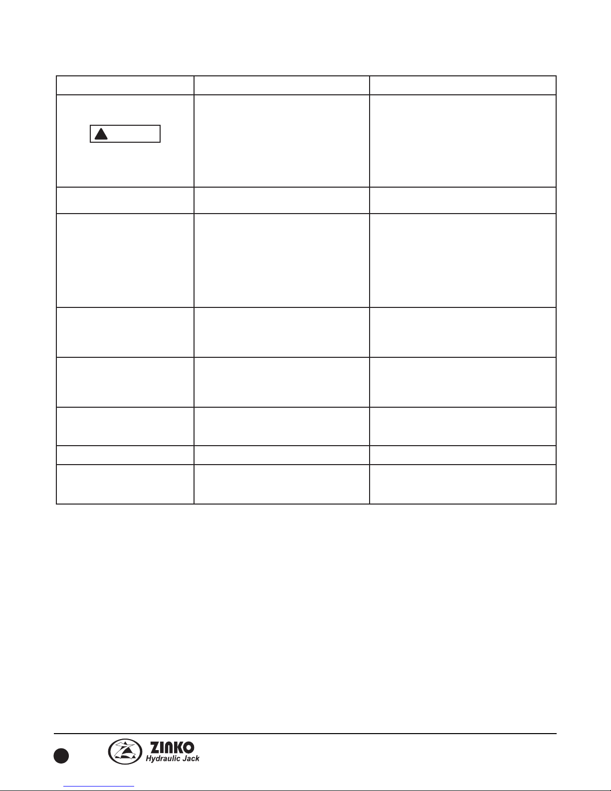
PROBLEM CAUSE SOLUTION
Motor Does Not Run.
Disconnect Power Supply
Before Disassembly or Repair.
1. No supply voltage.
2. Broken lead wire or defective power
cord plug.
3. Defective switches.
4. Worn carbon brushes.
5. Defective motor.
6. Defective remote switch.
7. Unit is not plugged in.
1. Check line voltage.
2. Replace defective part.
3. Check switches.
4. Replace carbon brushes (see page 4).
5. Repair or replace motor.
6. Repair or replace switch.
7. Plug in unit.
Abnormal Noise From Motor. 1. Damage to pump or motor.
2. Damage of ball bearings, etc.
1. Repair or replace unit.
2. Replace ball bearings.
Motor Runs, But Cylinders
Do Not Advance or Retract.
1. Damage of release valve.
2. Oil level is too low.
3. Air in the system.
4. Filter plugged or dirt in the pump.
5. Damage of the pump body.
6. Relief valve out of adjustment.
1. Repair or replace release valve.
2. Fill reservoir to 1/2 of level gauge with
all cylinders retracted.
3. Bleed the system (see page 4).
4. Pump filter should be dismantled and
cleaned if necessary.
5. Repair pump.
6. Readjust as needed.
Cylinders Work, But Full
Pressure is Not Reached.
1. Damage of release valve.
2. Air in the system.
3. Damage of the pump body.
4. Lowering of set pressure.
1. Repair or replace release valve.
2. Bleed the system (see page 4).
3. Repair pump.
4. Readjust set pressure.
1. Damage of release valve.
2. Air in the system.
3. Unacceptable rise in oil temperature.
4. Damage of the pump body.
Cylinders Work, But
Speed is Too Slow or Erratic.
1. Repair or replace release valve.
2. Bleed the system (see page 4).
3. Stop operation or install oil cooler.
4. Repair pump.
1. Damage of release valve.
2. Damaged cylinder return springs or
damaged quick couplers.
Cylinders Do Not Retract.
1. Repair or replace release valve.
2. Repair or replace springs or couplers.
1. Damaged seals, seats, or steel balls.Leaking Oil. 1. Replace damaged component(s).
1. Damaged cords.
2. Bad insulation of electric parts.
Short Circuit.
1. Replace damaged component(s).
2. Locate and replace damaged
component(s).
Troubleshooting
WARNING
!
Zinko Hydraulic Jack
Models: ZPE-35RH-1M & ZPE-35RH-1MB Troubleshooting
REV 110707
This manual suits for next models
1
Table of contents
Other Zinko Water Pump manuals
Popular Water Pump manuals by other brands

Graco
Graco 226012 Instructions-parts list

Grundfos
Grundfos BME Installation and operating instructions

MULTIQUIP
MULTIQUIP YELLOW SUBMARINE Operation and parts manual

Blue-White industries
Blue-White industries A3V series operating manual

aquanique
aquanique QFP320 manual

Regulus
Regulus CSE OTS MFB+ZV W Installation and operation manual

Varian
Varian Turbo-V70LP instruction manual

Masport
Masport HXL5W Owner's/operator's manual

LMI
LMI Milton Roy E7 Series instruction manual

Silicon Solar
Silicon Solar AquaJet SPB50-801210D user manual

Speck pumpen
Speck pumpen BADU 45 Installation and operation manual

Giant
Giant P200A-3100 Series Repair and Repair instructions