ZSA VARIO-VENT DUO User manual

by
DecentralizeD Ventilation Unit VARIO-VENT DUO
operating anD installation instrUctions

2
Contents
1. Introduction................................................................................................................................ 3
2. Delivery contents ...................................................................................................................... 3
3. Safety instructions .................................................................................................................... 4
4. Installation................................................................................................................................. 5
4.1 Installation instructions .................................................................................................................... 5
4.2 Ventilation unit installation ............................................................................................................. 5
4.3 Control panel installation .................................................................................................................9
5. Control panel operation............................................................................................................ 11
5.1 Control panel display ........................................................................................................................11
5.1.1 Main screen display ................................................................................................................11
5.1.2 Screen 2......................................................................................................................................11
5.1.3 Screen 3..................................................................................................................................... 12
5.1.4 Screen 4.................................................................................................................................... 12
5.2 Control Panel ................................................................................................................................... 12
5.2.1 Operating modes ................................................................................................................... 12
5.2.2 Symbols ................................................................................................................................... 14
6. Care and maintenance .............................................................................................................16
6.1 Cleaning the dust filter....................................................................................................................16
6.2 Cleaning the porcelain heat exchanger ...................................................................................... 17
6.3 Filter change ..................................................................................................................................... 18
7. Error message ...........................................................................................................................18
8. First Aid ....................................................................................................................................19
9. Warranty .................................................................................................................................. 20
10. Inspection certificate............................................................................................................. 20

3
1. Introduction
Dear Customer,
We would like to congratulate you on your
purchase of your decentralized ventilation
unit Vario-Vent DUO.
You have chosen a high quality product
“Made in Germany”.
Hygienic cleanliness, easy and whisper
quiet operation are convincing arguments
for choosing this product.
2. Delivery contents
1 x Casing tube
1 x Ventilation unit Vario-Vent DUO
2 x Porcelain heat exchanger
1 x Plaster guard with level
1 x Cover plate
2 x Lid for electronic box
1 x Outer hood, plastic or stainless steel
1 x Inner hood
4 x Closing flaps for the inner hood
4 x Filter holder
2 x Filter G3
1 x Control panel
6 x Screws and dowels
2 x Clamps
1 x Drilling template
6 x Wedges
1 x Sealing tape
1 x Operating and installation instructions
manual
Modern production facilities in Germany,
carefully selected materials and examined
quality are the basis of our five-year war-
ranty from the original purchase date.

4
3. Safety Instructions
Please read your Operating and Installa-
tion Instructions carefully and follow the
directions. Please keep your manual in a
safe place. You may need it in the future for
other useful information and tips.
The Vario-Vent DUO is designed to ventilate
rooms. This system is installed into the
exterior wall. This wall must have a mini-
mum width of 27 cm and may not be wider
than 56 cm.
A 230 volt electric power supply is needed.
The control voltage has 12 volt.
The use of the Vario-Vent DUO is only
permitted with the use of the dust filter.
This filter must be cleaned regularly and or
replaced.
The respective regional construction regula-
tions that apply must be followed.
The unit can only go into operation after all
construction work has been completed.
The unit is not suitable or permitted to be
used to dry out the building during the
construction phase.
For maintenance always disconnect the
power supply.
With the use of a fireplace please check
with a chimney sweep or specialist for
safety reasons.
This device is not intended to be used by
persons (including children) with limited
physical, sensory or mental aptitude or lack
of experience and/or knowledge unless
they are supervised by a person responsible
for their safety or have received instruc-
tion from this person as to how the device
is used.
The manufacturer cannot be made liable to
damages due to improper installations or
failure to follow the manufactures guide-
lines for proper use.

5
4.2 Ventilation unit installation
4. Installation
4.1 Installation instructions
On-site preparation:
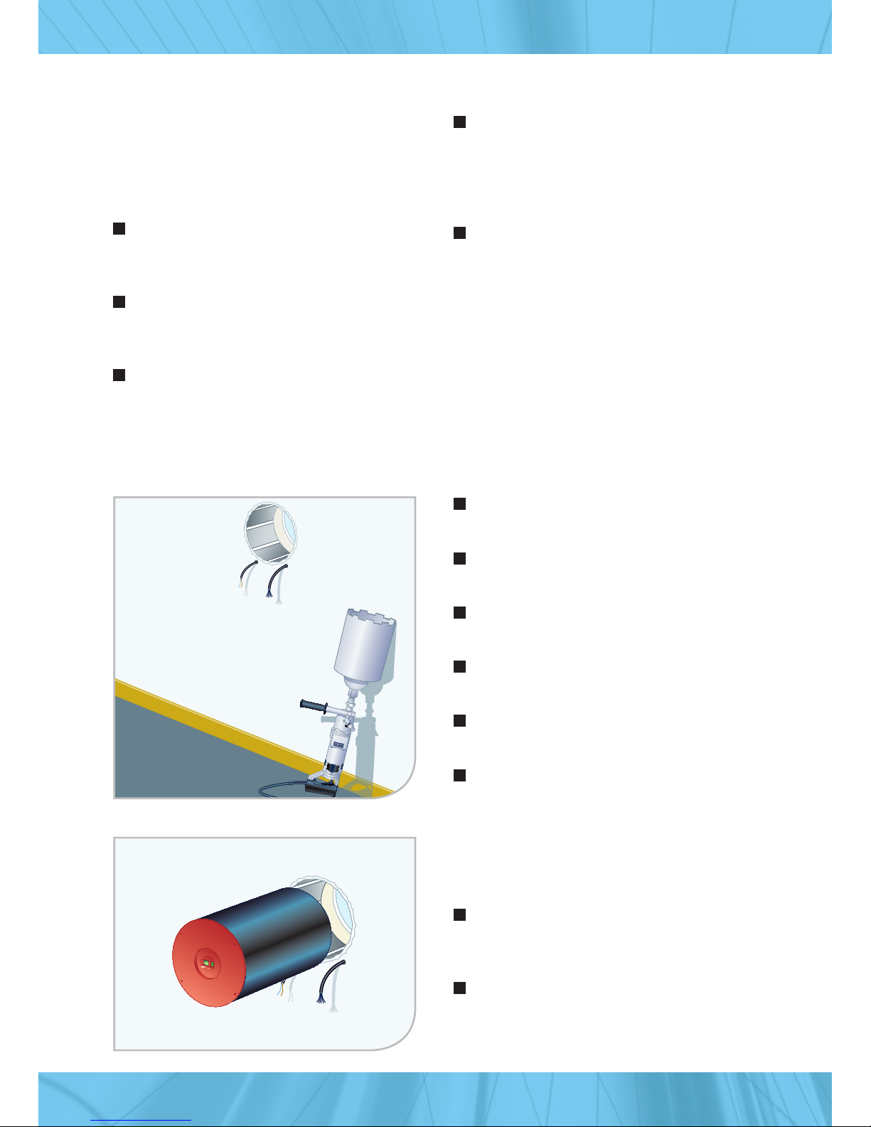
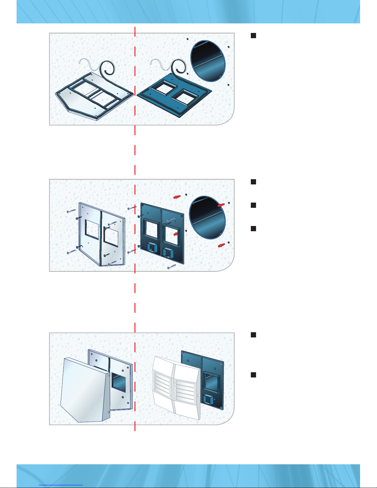
A core drilling of 290 to max. 300 mm
must be drilled in order to install the
Vario-Vent DUO.
The electrical supply of 230 volt must be
laid properly according to the specifica-
tions.
A 6 x 0,1 mm²control line must be in-
stalled between the Vario-Vent DUO and
the control panel.
Make a core drilling of 300 mm diameter
with a 1% decline toward the outside.
Cable for left side:
2 x 0,75 mm²for 230 volt
Cable for right side:
6 x 0,1 mm² to the control panel
Optional: additional cable right side:
min. 2 x 0,1 mm² additional input.
Take the measurements from the drilling
template.
Connection cables must be installed by
the customer on site.
A separate 2 x 0,1 mm²control line must
be available when using the additional
input. This is an additional switching
input that can be used with the software
as opened or closed.
For the exact measurement please use
the included drilling template.
Please examine the Vario-Vent DUO after it
is unpacked for any external damage that
may have occurred during transport. If you
notice any damages please contact us on
our service number located on the type
label. Please let us know the extent of
damage and the serial number of the
ventilation unit.
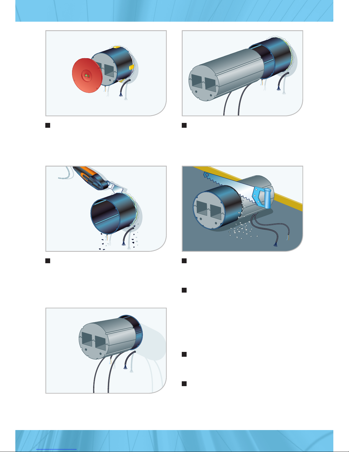
Insert the casting tube from the inside
to the outside. The casting tube must
be flush to the exterior finish wall.
The ventilation unit must be inserted
into the casting tube. The ventilations
fans must be pointed toward the
exterior wall.
Inside
Inside

6
Use the wedges to keep the casting
tube of the ventilation unit in place
and make a seal around it using special
construction foam.
The casting tube must be shortened on
both sides, flush to the finished wall.
Use the cutoff piece of the casting tube
as a template when shortening the
ventilation unit to size.
Caution: Do not damage the cable.
Remove the ventilation unit after the
foam has hardened.
Inside
Inside
Inside
Insert the shortened ventilation unit
from the inside as far as it will go into
the casting tube.
Make sure that the fans are pointing
toward the outer side.
Inside

7
Place the plastic cover
plate onto the cover
plate until it clicks into
place.
Alternative: Screw the
stainless steel cover
onto the cover plate.
Apply the sealing
tape to the backside
of the cover plate.
Mount the cover plate
from the outside
Fasten 4 x onto the
wall
Fasten 4 x onto the
casting tube
Outside
stainless steel
Outside
plastic
Outside
stainless steel
Outside
plastic
Outside stain-
less steel
Outside
plastic

8
Connect the cables together according
to the identification marking. 1-brown,
2-red (purple), 3-blue, 4-white, 5-green,
6-yellow. The two other colors are for
the additional input.
Close the electronic boxes with the
covers.
Insert filter holder nr. 1
Insert filter
Insert filter holder nr. 2
Mount the inside cover plate by pressing
the clips on the right and left side.
Mount the cover plate
Fasten 4 x onto the wall
Fasten 4 x onto the casting tube
Insert the cable into the electronic box
Inside

9
Information: 4 closing flaps are included
to completely air tighten the unit from
the inside cover panel.
Place the flaps on the outside of the
interior cover panel to seal the air slots.
We also recommend turning the unit off.
Connect the wires from left to right into
the clamp. Please make sure to follow
the number/color code.
Break out the middle piece of the frame
and guide the cable through. Then
attach the frame to wall and or the wall
mounted box.
There must be a 6-wire control line
(6 x 0,1 mm² minimum) installed from the
ventilation unit to the control panel. Max
length should not exceed 25 meters.
1-brown, 2-red (purple), 3-blue, 4-white,
5-green, 6-yellow
4.3 Control panel installation
1
It is recommended to use a flush mounted
box when installing the control panel. This
makes the installation much easier.

10
Set the desired operating mode.
The interface of the control panel allows
you to view the operations and adjust
settings with the service software.
The service software is to be ordered
separately and only to be programmed
by a skilled tradesman.
Insert the clamp onto the back side of
the control panel.
Attach the control panel to the frame.
Start from the top of the frame.
Now activate the 230 volt cable and the
Vario-Vent DUO is ready for use.
654321

11
5.1.2 Screen 2
This picture shows the screen after it
has been scrolled to “screen 2” in the
navigation bar.
Confirming with enter (checkmark)
allows access to the selections.
While selecting the operating mode with
the up/down buttons the display shows
the current operation function that has
been selected. The display of the opera-
tion symbols changes when pressing the
up/down buttons.
Confirming with enter (checkmark)
allows access to the fan stages
While selecting the fan stages with the
up/down buttons the display shows the
current stage that has been selected. The
display and the fan stages change with
the use of the up/down buttons (stage
0 display no bars, stage 4 display four
bars).
Fan stage selection display
5. Control panel operation
5.1 Control panel display
5.1.1 Main screen display
The navigation bar is located all the way
on the left hand side. This shows the
number of the screen you are currently
on. It allows you to scroll through the
different screens.
Next to the navigation bar is the opera-
tion symbol (current setting) shown
(normal operation with heat recovery).
The middle position (next to the opera-
tion symbol) displays the current fan
stage. The picture displays the active
(running) fan on stage 4. If the unit is
set on stage 4 and not in use the display
will show only the outline of the bars.
When turning the fan stage down one
stage, one bar (beginning at the top) will
disappear from the display.
Error symbols and or service require-
ments are displayed to the right of the
fan stage (not displayed in the picture).

12
5.1.3 Screen 3 5.1.4 Screen 4
Display of the error messages such as
filter change, battery lever etc.
The fourth screen shows the logo of
the distribution partner and the serial
number of the unit.
1311
0
7
00
4
4
Normal operation with heat recovery
The fans are running on the set stage in opposite directions and
change directions every 70 seconds. This time may change
according to the preset that has been chosen with the software.
Normal operation with heat recovery and day/night regulation
The fans are running on the set stage in opposite directions and
change directions every 70 seconds. This time may change accord-
ing to the preset that has been chosen with the software. The fans
are on stage 1 between 7 pm and 7 am.
5.2 Control panel
The control panel allows you to choose and set different operating modes.
5.2.1 Operating modes
Summer operation without heat recovery
The fans are running on the set stage in opposite directions without
direction changes.

13
Summer operation without heat recovery and day/night
regulation
The fans are running on the set stage in opposite directions without
direction changes. The fans are on stage 1 between 7 pm and 7 am.
Moisture protection ventilation
If the humidity rises above the set value, for exp. 55 %, the fans will
run in opposite directions at the set fan stage. When the humidity
drops below that value the fan will then shut off. The values can be
set with the service software by a skilled tradesman.
Moisture protection ventilation and day/night regulation
Same function as the “moisture protection ventilation”. The fans are
also on stage 1 between 7pm and 7am. The values can be set with
the service software by a skilled tradesman.
Exhaust air operation
Both fans are running on the set stage blowing the air toward the
outside.
Ventilation while absent
The fans are running on the set stage in opposite directions just like
in the “normal operation”. The fans run at an interval for 15 minutes
every 2 hours.
Incoming air operation
Both fans are running on the set stage blowing the air toward the
inside.

14
5.2.2 Symbols
The control panel allows you to set fan stages and displays error messages. When an error
message is displayed the ventilation unit will shut off until the error is fixed. (Except for filter
change)
Filter
In connection with the
“enter” key: Filter is
functioning.
In connection with alarm
symbol: Filter change is
necessary.
Additional input
In connection with the “ON“ symbol: Additional input is
functioning.
In connection with the “OFF” symbol: Additional input is not
functioning.
Power supply
In connection with the
“enter” key: Power supply
is functioning.
In connection with the
alarm symbol: Power
supply is disconnected
Battery
In connection with the
“enter” key: Battery is full.
In connection with the alarm
symbol: Battery is empty.
Moisture sensor
In connection with the
“enter” key: Moisture
sensor is active.
In connection with the
alarm symbol: Moisture
sensor in not active.
For example: A smoke detector or a depression sensor
can be connected.
Opener Closer

15
Exit
Exit out of a function.
Alarm symbol
Please check the error message on screen 3. Make sure to eliminate
the problem displayed.
Up/Down
Toggle up and down through the menu.
Enter
Functions are operating properly. “Enter” is also used to confirm
your selection.

16
Remove the filter holder from the side
and take out the dust filter.
The filter can be rinsed out under
running water.
Remover the inner hood by pressing the
latches on the right and left side.
6. Care/maintenance
6.1 Cleaning the dust filter
Make sure to reinsert the filter and filter
holder after it is completely dry.
Re-insert the filter and filter holder.
Clean the entire inner hood with a damp
rag.
Mount the inner hood by pressing the
latches on the right and left side.

17
Remove both filter holders and filters.
Pull out the porcelain heat exchanger.
Clean the heat exchanger with a vacuum
cleaner or place them into the dish-
washer (by 30°C without dishes).
Reinsert the heat exchanger, filter and
filter holder. Make sure to push the heat
exchanger as far back as possible.
Remover the inner hood by pressing the
clips on the right and left side.
6.2 Cleaning the porcelain heat exchanger
Clean the entire inner hood with a damp
rag.
Mount the inner hood by pressing the
clips on the right and left side.

18
7. Error message
The main screen displays all error/alarm
messages.
Switch to screen 3 to see witch error/
alarm message is displayed.
IN
OFF
IN
OFF
IN
OFF
You can select the alarm symbol with
the enter button (checkmark).
Press the enter button (checkmark)
again to reset the exchange interval.
The alarm symbol lights up behind the
filter symbol.
6.3 Filter change
The alarm symbol is displayed behind
each symbol. (See 5.2.2)

19
8. First aid
In case of an error display, please use this help list to see if the problem can be solved by
following these steps mentioned below.
Problem Possible cause Help aid
Fans are not working No power supply Please check the power supply
Wrong operation mode Please check the operation mode
Installation error Please check the wiring
Fan is stuck Please remove the object
Control panel is broken Please replace the control panel
Fan is broken Please call customer service
Low air flow rate Wrong operation mode Please check the operation mode
Filter is blocked Please clean the filter
Porcelain heat exchanger is
blocked Please clean the porcelain heat
exchanger
Control panel not functioning Control panel is hung up Press the enter button (checkmark) &
the exit button (X) at the same time
and hold for 2 seconds. The control
panel will then restart.

ZS VT BA GB 1403
All technical data are factory specifications. Technical data are subject to change!
9. Warranty
10. Inspection certificate
Our “general conditions” apply to our
scheduled date of delivery unless otherwise
specified. Our conditions are found on our
website: www.zsa-online.de. The unit has
a 5 year manufacturer’s warranty form the
time of commissioning, however begins at
the latest 3 months after ex-works delivery
date.
During the warranty period faulty units may
be replaced or repaired. Please contact your
contract partner.
After the warranty period has expired,
repairs carried out or repairs not covered by
the warranty are invoiced.
Table of contents
Popular Fan manuals by other brands

Ebmpapst
Ebmpapst R3G630-AB06-03 operating instructions

Homebase
Homebase 647422 instruction manual

Delta
Delta BreezIntegrity ITG80 Installation and operating instructions

oneConcept
oneConcept 10029726 Instruction

Ebmpapst
Ebmpapst R2D180-AL02-15 operating instructions

Pro Breeze
Pro Breeze PB-F04 instruction manual