The quick guide is for quick installing this product. For details, please refer to the camera’s User Manual.
Installation Guide
Lead cables through ceiling or side of the semi-dome camera according to the installation condition. If from side
of camera, unscrew the screw on the side and remove the thin wall of the line outlet with pliers and debur it, as
shwon in
1. Outgoing Line Mode
Figure 1.
Figure 1Outgoing from Side Figure 2 Install Expansion Screw Sleeve
Drill four Φ6 holes (center distance of holes are 90*86.8mm) with an impact drill on the mounting plate. Press four
Φ6 screw sleeves into the holes (supplied with accessories); If lead cables through ceiling, drill an outlet first.
The location of outlet should be determined appropriately based on the bottom case of the semi-dome camera,
as shown in Figure 2.
2 Install expansion screw sleeve
Connect cables, including video, alarm, power, audio, and network cables, by tags as per Figure 16 and Table 1.
3 Connect Cables
To install TF card, please perform the following steps: 1) Open the bottom cover; 2) Place TF card on PCB
flatly; 3) Insert TF card into the TF card socket as in the direction of arrow, as shown in
4 Install TF Card
Figure 3.
To pull out TF card, please perform the following steps: 1) Push the TF card in the direction of the arrow,
then release; 2) Take the TF card out at about 1cm from TF card socket, as shown in Figure 4.
Figure 3 Install TF Card and Adjust Brightness Figure 4 Pull out TF Card
For HD manual zoom color semi-dome IP camera, it is required to adjust brightness. To do so, please perform
the following steps: Adjust brightness regulator is as shown in
5 Adjust Brightness
Figure 3.Adjust the regulator to proper position,
clockwise to increase the brightness, counterclockwise to decrease, as shown in Figure 5.
Figure 5 TF Card Installation and Brightness Adjustment Figure 6 Bottom Case Installation
Take the four O-shape silicone rings (Spec: D8*2.5) and the four tapping screws (Spec: BA4*25) out from the
accessory bag, put the four silicone rings onto the four tapping screws, and then pass them through the four
holes on the bottom case and aim them at the four expansion screw sleeves on the ceiling, fasten them with
cross screw driver, as shown in Figure.
6 Lock the bottom case onto ceiling
(1) Aim the lens at the target direction, rotate it in horizontal (0-3600) and vertical (±600) directions respectively to
adjust, and then tighten the thumb screws at both sides of the U-shape bracket, as shown in
7 Adjust HD Semi-dome IP Camera from Three-axis
Figure 7.
Figure 7 Three-axis Adjustment Figure 8Adjust Optical Axis of Lens
(2) Confirm the image formed is exactly consistent with actual observed scene, if any inversion or deflection,
loosen the thumb screws and rotate the camera to adjust the optical axis within 3600till the image is totally fit
with the actual situation, then tighten the two screws, as shown in Figure 8.
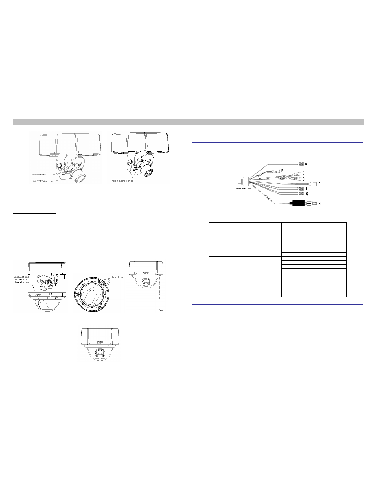
For manual zoom lens, the focal length of lens is required to be adjusted. To adjust it, perform the following:
Loosen the focus control bolt, then adjust the focal length to an appropriate position by rotating the focal length
adjusting bolt toward “T” or “W”, tighten the focus control bolt, then loosen the focal length adjust bolt and rotate
the focusing ring clock/counterclock-wise till the optimum image effect is obtained, as shown in
8 Adjust Lens
Figure 9.