Chapter 3. Installing CT28 on the
Wall Bracket
Critical information
Attention: This wall-mount bracket is intended for installation by
qualified professionals.
Notice: Please read these instructions carefully and completely
before attempting installation.
WARNING
Improper installation or suspension of any heavy load
can result in death or serious injury to persons, as well
as damage to property.
It is the responsibility of the installation personnel to
verify and guaranty the reliability and safety of the
installation.
Notice: This product must be installed in compliance with all
applicable local, state and national regulatory provisions. The
responsibility rests with the installer to verify that the installation
is carried out in accordance with any applicable legislation.
Important: The installer must assess the appropriate stability
andsturdinessofthe mountingsurface. Inthe caseof wall-mount
and ceiling-mount brackets, this includes, but is not limited to
verifying the positions of suitable studs in the case of drywall
mounts, hollow points in concrete block or solid concrete, as well
as the presence and vicinity of electrical wiring or plumbing.
Restriction: Only hardware and accessories included with
the product or specified by 1 Sound should be used for its
installation.
Restriction: Do not modify or alter the loudspeaker or any
accessory. Any modification by the user or installer could render
the product or the installation unsafe.
Restriction: Do not install a loudspeaker or any accessory near
any open flame or heat source.
Products, accessories and tools required
To install a CT28 enclosure permanently on a wall or surface using the
Horizontal Mounting Bracket, you will need the following:
•A CT28 loudspeaker enclosure
•The CT28 Wall Bracket kit
•An appropriate power drill and bit for the installation surface
material
•A 4 mm hex driver and/or a 4 mm hex wrench (Allen)
•A 5 mm hex wrench (Allen)
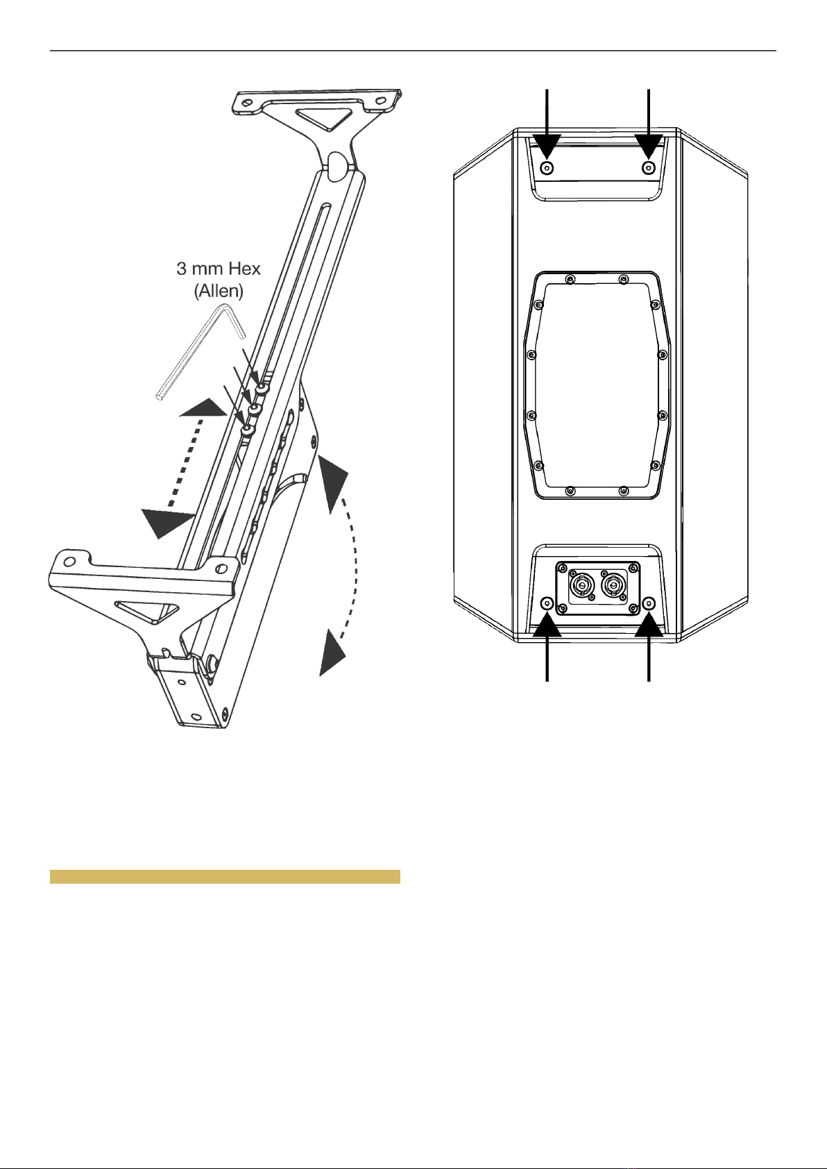
•A 3 mm hex wrench (Allen)
•Medium-duty mounting screws or bolts appropriate to the
mounting surface (coach screws for drywall studs, concrete
screw anchors for concrete or masonry, etc.); screws and bolts
should have a flanged head or a coupled washer ø14-16 mm in
order to retain the mounting plate
•Appropriate tools for securing the aforementioned fasteners
(power screwdriver etc.)
•A Torque wrench
•Optional: a short two-leg steel wire rope bridle, 2 × M5 lifting eye
bolt (shouldered type); eye bolt spanner or driver
•Recommended: pencil or marker, spirit level, stud finder
Procedures
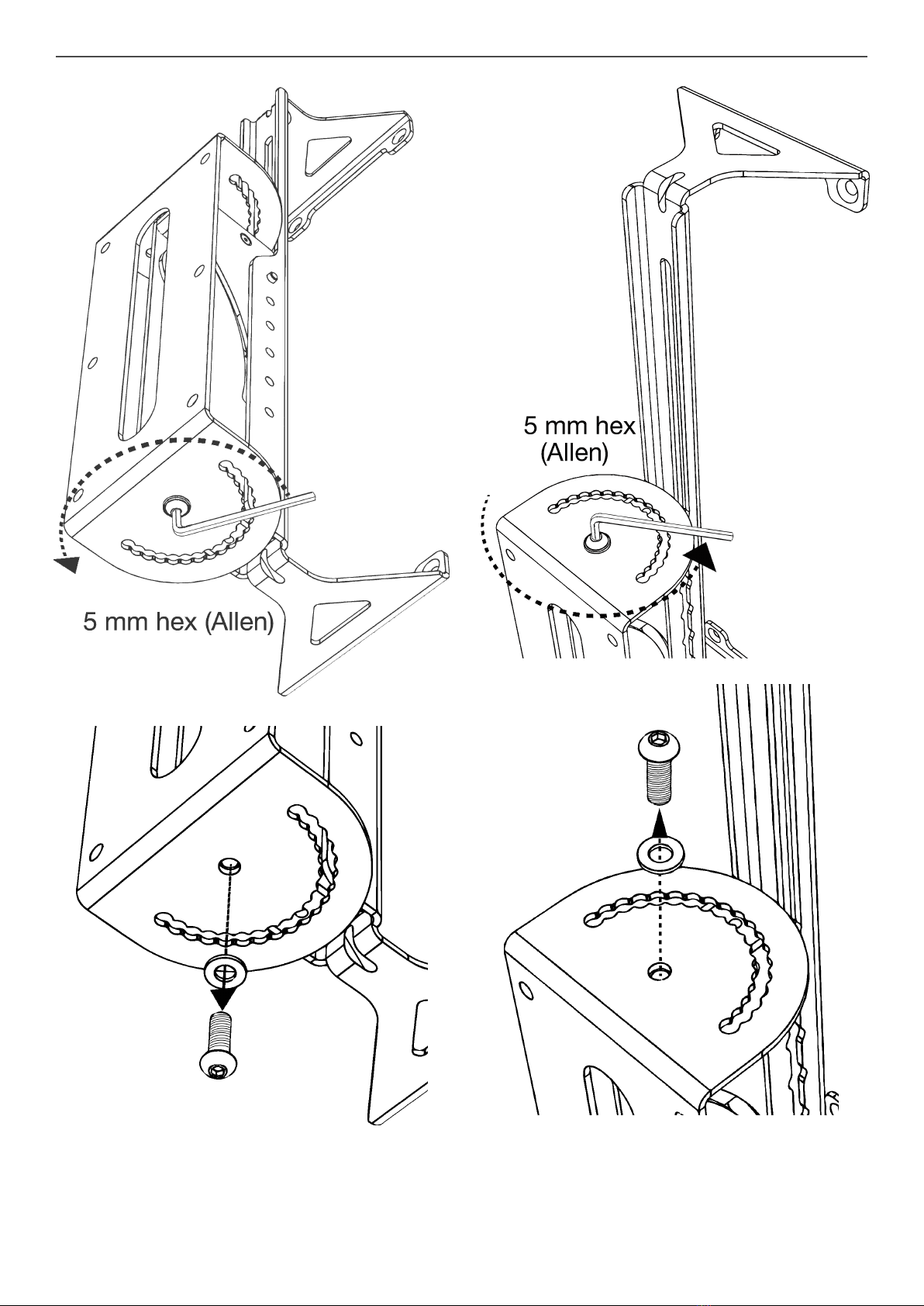
Disassembling the CT28 Wall Bracket
The Wall Bracket ships fully assembled, but to facilitate installation, it
should first be separated into two parts, the bracket arm with the tilt
mechanism, and the wall-mounted yoke with the pan-fixing mechanism.
Before disassembly, be sure to note the proper interlocking configuration
of the Bracket; this will remove doubts when it is time to reassemble the
bracket.
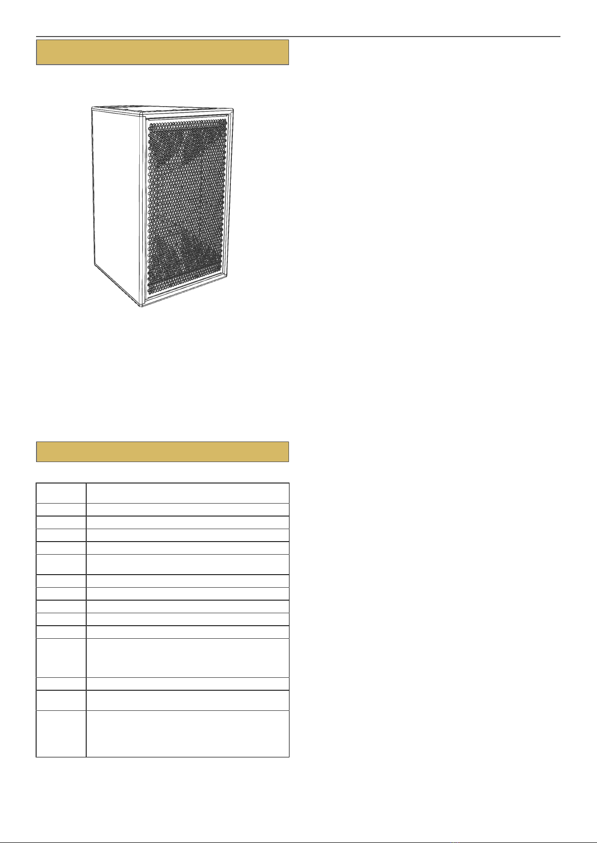
Figure 5. The CT28 Wall Bracket.