3D R Solo User manual

Thermal Gimbal
for the
3DR SOLO
Installation Instructions
P.O. Box 4242 Middletown, New York 10941 USA
Phone: 1-888-919-2263 | Outside the U.S.: +1-845-343-4077 | Fax Line: +1-845-343-4299
Version 1.3
10MAR2017

THERMAL GIMBAL FOR 3DR SOLO MANUAL
Safety Notes
2
SAFETY NOTES:
Product Notes:
•Do not disassemble or attempt to repair the product by yourself.
•Do handle the product properly. This product may be damaged ifdropped.
•Do not use corrosive, alcoholic or organic-solvent-containing cleaners to wipethis
product.
•Do not use or store this product in high temperature environment.
•If the product is quickly transferred from a low temperature environment to a high
temperature environment, water condensation may occur in the product due to physical
changes. In this case, it is recommended to wait until the product returns to room tem-
perature before turning iton.
•Store the product in a dry and clean environment when storing the product for a long
period of time.
•Do not disconnect the power or turn the product off during firmware updating process.
Doing so may cause incorrect data to be written and the product may not power onlater.
•After using the product in the presence of sand, mud or other foreign matter, wipe the
gimbal with a clean, dry, lint-free cloth.
•This product is intended for use solely with the FLIR VUE, FLIR VUE PRO andFLIR
VUE PRO-R Series of Thermal ImagingCameras.
Do not Use this product with any other device other than the 3DR Solo as it may cause
damage to the gimbal assembly or the other device it is connected to.

3
THERMAL GIMBAL FOR 3DR SOLO MANUAL
Modification Notice & Instructions
MODIFICATION NOTICE & INSTRUCTIONS:
NOTICE:
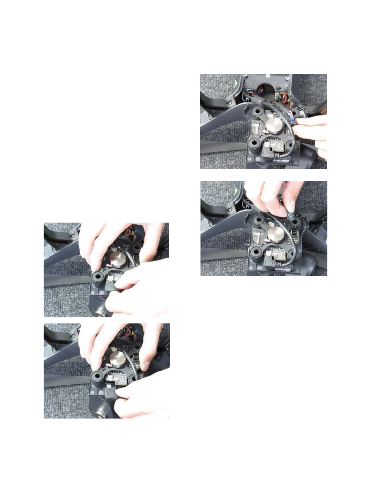
In order to take advantage of the controlling features, the FLIR VUE PRO and
FLIR VUE PRO-R Thermal Imaging Cameras will require a modification. This modification can
be performed by OEM Cameras at no charge and the warranty on your thermal camera will not
be void.
You will be able to control all parameters remotely on the FLIR VUE via the 3DR Solo APP
directly out of the box with no camera modifications required.
For the FLIR VUE PRO/VUE PRO-R modifications, please contact OEM Cameras for a Return
Authorization and shipping instructions to our facility in New York.
•
E-Mail:
• Toll Free: 1-888-919-2263
• Outside the US: +1-845-343-4077
The VUE PRO Series modifications will allow you to control the following parameters remotely
via the 3DR Solo APP:
•
Color Palette: - 3 Choices
•
Camera Digital Zoom: 1x, 2x, 4x
•
Flat-Field Correction/FFC (Manual)
•
Region of interest (ROI): - 3Choices
•
Scene Presets: - 3 Choices
•
Start and Stop Image Sequence or Video Capture on the VUE PRO or VUE PRO-R’s
Internal Micro SDCard
On the VUE PRO and PRO-R at this time only two (2) parameters can be set and adjusted
remotely. These parameters are set by connecting to the camera via Bluetooth using the FLIR
VUE PRO APP on your iOS or Android Device.
iOS APP: http://apple.co/2dT688Q
Android APP: http://bit.ly/2eyC0jj
Without VUE PRO or VUE PRO-R modifications, you will only be able to view the cameras
images on your iOS or Android device and Record or Capture images on your iOS or Android
device using the 3DR Solo APP.

4
THERMAL GIMBAL FOR 3DR SOLO MANUAL
FLIR VUE/VUE PRO Installation
CONNECTING THE GIMBAL TO THE VUE/VUE PRO SERIES THERMAL CAMERAS:
In this section we will show how to:
•
Connect the FLIR VUE Thermal Camera to theGimbal
•
Connect the FLIR VUE PRO / PRO-R Thermal Camera to theGimbal
NOTE: THE VUE SERIES CAMERAS SHOULD BE INSTALLED TO THE GIMBAL BEFORE
ATTACHING THE GIMBAL TO THE 3DR SOLO.
Before installing the camera to the Gimbal, please remove the battery and any other power source
that may be connected.
FLIR VUE PRO-R USERS:
Before you begin, please remove the FLIR
band attached to the outside of the Thermal
Camera. There are four allen screws. Store in
a safe place for future use.(Fig. 1)
There are three steps for attaching the FLIR VUE
Series Thermal imaging camera to the Gimbal.
Step 1:
With the supplied allen key, detach the cover plate
by removing the short allen-head screw on the side
of the gimbal and set aside. (Fig. 2&3)

5
THERMAL GIMBAL FOR 3DR SOLO MANUAL
FLIR VUE/VUE PRO Installation
CONNECTING THE GIMBAL TO THE VUE/VUE PRO SERIES THERMAL CAMERAS:
Step 3:
Plug the USB connector on the gimbal, intothe
VUE Series Camera and secure using the four
short allen-head screws provided. (Fig. 6)
Step 2:
Align to the USB Connector to the cover plate.
The holes are aligned differently on the VUE
PRO/PRO-R. (Fig. 4&5)
Use the long allen-head screws provided, to
mount the plate on the camera.

6
THERMAL GIMBAL FOR 3DR SOLO MANUAL
Installing theGimbal
GIMBAL INSTALLATION:
In this section we will show how to:
•
Disconnect the Current Gimbal.
•
Connect the Thermal Gimbal Assembly to the 3DR SOLO.
Before You Begin:
Before installing, please remove the battery or any power source from the 3DR SOLO.
Removing the cover plate:
If there is no Gimbal attached, the cover
plate will need to be removed. The plate
is attached with three screws on the 3DR
SOLO. Loosen the self retaining screws
with the provided Phillips screwdriver.
Store the plate in a safe place for future
use. (Fig. 7)
There are two cables inside the body of the
3DR SOLO. Carefully bring them out of
the drone. They will connect to the board
of the Gimbal in the steps following this
procedure. (Fig. 8)

7
THERMAL GIMBAL FOR 3DR SOLO MANUAL
Installing theGimbal
GIMBAL INSTALLATION:
Uninstalling your current Gimbal Assembly:
If you have a gimbal currently attached to the SOLO, it will need to be re-
moved before installing the 3DR Solo Thermal Gimbal Assembly.
Loosen the three self retaining screws with
the provided Phillips screwdriver.
Carefully lift up the Gimbal assembly from
the drone while pressing in on the two tabs
near the front legs. (Fig. 9)
The Gimbal should release.
Carefully lift off, and set in front of the
SOLO as shown.
The two cables attached will need to be
disconnected. (Fig. 10)

8
THERMAL GIMBAL FOR 3DR SOLO MANUAL
Installing theGimbal
GIMBAL INSTALLATION:
Disconnect the Power / Data Cable by pressing
the locking tab and gently lifting the connec-
tor straight up from the board as shown: (Fig.
11&12)
To disconnect the HDMI cable, gently sepa-
rate the cable from the connection by pulling
away from the board. (Fig. 13&14)
Once you have disconnected both cables,
store the existing gimbal in a safe place for
future use.

9
THERMAL GIMBAL FOR 3DR SOLO MANUAL
Installing theGimbal
GIMBAL INSTALLATION:
The Philips screwdriver (included), will be the only tool needed for installation.
Before connecting:
The three position Camera Select Switch will allow the thermal gimbal to pass certain information
to the remote controller and the 3DR Solo App.
Be sure to select the correct position before connecting the HDMI cable.
Position 1 - FLIR VUE CAMERA:
This position allows the control of the FLIR VUE
and adjustments through the 3DR App.
Position 2* - FLIR VUE PRO/PRO-R Camera:
This position allows the control of the VUE
PRO or VUE PRO-R. Adjustments can be made
through the 3DR App.
Position 3* - This position will disable control
through the 3DR App and pass MAVLINK/GPS
Data from the SOLO to the VUE PRO and VUE
PRO-R. (Fig. 15)
(
*See Page 3 for Modification Details.
)
When the desired toggle switch position has
been selected, connect the HDMI Cable to the
HDMI port and the Gimbal Data Cable to the
port as shown. (Fig. 16)

THERMAL GIMBAL FOR 3DR SOLO MANUAL
Attaching theGimbal
10
ATTACHING THE GIMBAL ASSEMBLY TO THE 3DR SOLO:
Attaching the Gimbal to the 3DR SOLO:
Tuck the excess cable into the 3DR SOLO
making certain that the wires are not pinched
between the seams. (Fig. 17)
With the screwdriver provided, tighten the
three mounting screws to secure the gimbal to
the 3DR SOLO.
The 3DR Thermal Gimbal is now installed and
ready for flight testing.
Flight Testing:
Follow the pre-flight testing procedures as per
the operating manual for the 3DR Solo. (Fig.
19)
Gently place the gimbal assembly into
position.
The three mounting screws should line up
with the holes on the SOLO. (Fig. 18)

THERMAL GIMBAL FOR 3DR SOLO MANUAL
Attaching the Leg Extenders
ATTACHING THE LEG EXTENDERS:
To ensure clearance of the thermal camera, we have provided leg extensions
for the 3DR SOLO.
To Install:
First remove the existing feetfrom
the 3DR SOLO Legs by pulling
straight up. Store in a safe place
for future use. (Fig. 20)
Install the leg extenders by sliding
on with the angle facing to the
outside. (Fig. 21)
Be certain that the leg extenders are
flush with the end of leg as shown.
(Fig. 22)
11

THERMAL GIMBAL FOR 3DR SOLO MANUAL
PWM Setup
12
ASSIGNING PWM FUNCTIONS:
In this section we will show how to:
•
Assign and configure PWM Functions in the FLIR VUE PRO/PRO-R App
FLIR VUE PRO/PRO-R Modification:
Withoutthemodification,theFLIRVUE PRO &VUEPRO-Rwillonlyallow forStabilizedVideoand Tilt
Control. Recording from the camera to the SD card will not be available from the 3DR Solo App.
See Page 3 for more information regarding the modification.
PWM Settings
These setting changes should be performed prior to flight.
NOTE: Before you begin, be sure that the settings are set to the following suggested values.
PWM's cannot share the same configuration.
If channels 3 & 4 are enabled, they will need to be set to "DISABLED" before
configuring PWM 1 & 2.
Open the FLIR VUE PRO App on your mobile device and
enter the settings panel.
Select the ACCY. PORT Tab.
Touch on the Serial Protocol drop down and select: PWM
(Fig. 23)
Next we will define the parameters for the FLIR VUE PRO/
PRO-R to operate with the 3DR SOLO APP.
Select Channel 1:
This will open the configuration screen for Channel 1.
(Fig. 24)

13
THERMAL GIMBAL FOR 3DR SOLO MANUAL
PWM Setup
ASSIGNING PWM FUNCTIONS:
Select
Record Start/Stop
from the Dropdown Menu
(Fig. 25)
Once the Record Start/Stop is selected, The configuration
window will show the following options:
Number of States:
This should be set to TWO.
State Low:
Set to Stop Recording. This will send the signal to stop
recording to the FLIR VUE PRO/PRO-R SD Card.
State High:
Set to Start Recording. This will send the signal to begin
recording to the FLIR VUE PRO/PRO-R SD Card.
(Fig. 26)
Touch on the return arrow to go back to the previous
screen.
Next Select Channel 2:
This will allow one of the following
options:
•Color Palette
•Camera zoom level: 1x, 2x, 4x
•Recalibrate
•Region of interest (ROI)
•Scene Preset (Scene)
(Fig. 27)

14
THERMAL GIMBAL FOR 3DR SOLO MANUAL
PWM Setup
ASSIGNING PWM FUNCTIONS:
For this example, we are going to choose: Color Palette.
Next we will change the settings that determine what will
happen with the assigned control.
(Fig. 28)
The number of states can be set to two or three. In
this example we have chosen three.
This setting will allow us to choose between three
palettes during flight.
The following states (Low, Mid, High) can be set to
any palette.
To control these options, they will be assigned to the
Field of View (FOV) camera settings on the 3DR
Solo App. (Fig. 29)

15
THERMAL GIMBAL FOR 3DR SOLO MANUAL
PWM Setup
ASSIGNING PWM FUNCTIONS:
Touching on the palette, choose one of the following:
•
WhiteHot
•
BlackHot
•
GreenHot
•
Fusion
•
Ironbow
•
Lava
•
Arctic
•
GreyRed
•
InstAlert
Repeat this step for the next two States (Mid & High).
(Fig. 30)
When Configuration is complete, touch on the back
arrow to the Settings/Accy. Port screen.
These settings will be saved and the application may be
closed at this time.
We have included a reference of available options at the
end of this manual. (Fig. 31)

16
THERMAL GIMBAL FOR 3DR SOLO MANUAL
3DR SOLO App Configuration and Setup
3DR SOLO GOPRO APP AND PWM ASSIGNMENTS:
Now that the PWM functions are set, the 3DR GoPro App will recognize the functions from the two or
three states as follows:
•
Wide on the 3DR App, is assigned to the first state selected from the VUE PRO App.
In this example we chose: WhiteHot.
•
Medium on the 3DR App, is assigned to the second state selected from the VUE PRO App.
In this example we chose: Fusion.
•
Narrow on the 3DR App, is assigned to the third state selected from the VUE PROApp.
In this example we chose:
Arctic.
PLEASE NOTE: These states cannot change while recording.
Controlling the Thermal Camera through the GoPro App Control panel:
Wehave adapted the Thermal Gimbal to work with the 3DR Solo GoPro App control panel on the iOS or
Android Device.
Camera Controls and Settings
The Record button on right side of the main App screen allows start
and stop recording, with the FLIR VUE Series Camera.
When Video Mode is active the button is red. The button will ap-
pear grey when it is inactive or not connected. When recording
video, the red circle changes to a smaller square and the small
“LED” icon above the button pulses red.
To stop recording, tap the square button. (Fig. 32)
Fo
r
more information, see pages 21-23 for a reference o
f
available options.

17
THERMAL GIMBAL FOR 3DR SOLO MANUAL
3DR SOLO App Configuration and Setup
3DR SOLO GoPro APP AND PWM ASSIGNMENTS:
Control options vary for each camera:
The FLIR VUE PRO & PRO-R
– Records to Camera
Roll
and SD Card
The FLIR VUE PRO & PRO-R GPS Data – Records to Camera
Roll.
To record this data to the SD
Card, the recording will need to be initiated on the camera before takeoff.
FLIR VUE
– will record to the Camera
Roll
only. There is no SD Card option on the FLIR VUE.
The area just above the button contains status icons. From left to right, these are
•
Camera Roll (recording video to the mobile device)
•
Camera Icon (recording video to the camera),
•
Video-Recordingstatus
Below the button is a sliders icon that provides access to camera settings.
The following illustration shows different states of the record button and associated icons:
•
A: Video mode, not recording
•
B: Video mode, recording (note camera settingsdisabled)
•
C: Video mode, Camera recording disabled (Gimbal/Camera is notconnected)
•
D: Video mode, Camera Roll recording disabled by Camera Settingscontrol
(Fig. 33)

18
THERMAL GIMBAL FOR 3DR SOLO MANUAL
3DR SOLO App Configuration and Setup
3DR SOLO APP AND PWM ASSIGNMENTS:
To access the camera settings,
tap the sliders icon immediately
below the record button:
(Fig. 34)
Tip: Once recording is engaged, the settings are locked out. Stop recording to change
camera settings whileflying.
The two camera-settings areas, available from the buttons on the right side of the screen, are
Camera Mode and Camera Settings.
Camera Mode: Will only work in Video Mode, to
record continuous video, start and stop.
Photo/Burst Mode is not available for use at this
time. The VUE PRO Thermal Imager can be set to
photo mode through the FLIR VUE PRO App.
Camera Settings: will be automatically set to
GoPro Silver.
No further adjustment will be necessary.
FOV: Will control the additional PWMchannel
(PWM 2) which can be setup in the FLIR VUE
PRO App before flight.
(Fig. 35)

19
THERMAL GIMBAL FOR 3DR SOLO MANUAL
Enabling MAVLin
k
USING MAVLINK WITH THE 3DR SOLO GIMBAL ASSEMBLY:
Beforeyoubegin:TheGimbalCameraSelectSwitchwillneedtobesettoposition 3:VUEPROGPS.
See page 9 for details on this setting.
In this section we will show how to:
•
Assign and configure MAVLinkFunction
FLIR VUE PRO/PRO-R Modification:
Withoutthemodification,theFLIRVUE PRO &VUEPRO-Rwillonlyallow forStabilizedVideoand Tilt
Control. Recording from the camera to the SD card will not be available from the 3DR Solo App.
See Page 3 for more information regarding the modification.
MAVLink
The VUE PRO/VUE PRO-R can be configured to use this bus to capture available telemetry
data provided by GPS, altimeter, accelerometers, etc.
This data is saved as standard EXIF metadata in Still Image files (JPEG & TIFF) on the SD
Card.
This data is not saved to Video files as there is no current standard for doing this. Metadata
is accessible thru standard photo editing applications, file explorers, and suggested mapping
applications.
MAVLink Settings
These setting changes should be performed prior to flight.
NOTE: Before you begin, ensure that the following settings are set to the following suggested values.
Open the settings panel on the FLIR VUE PRO/PRO-R App and
select the ACCY. PORT Tab.
Touch on the Serial Protocol drop down and select: MAVLink
(Fig. 36)

THERMAL GIMBAL FOR 3DR SOLO MANUAL
Enabling MAVLin
k
20
USING MAVLINK WITH THE SOLO GIMBAL ASSEMBLY:
These settings should default to the correct
information.
NOTE: The Serial DataRate must be set to
57600.
(Fig. 37)
When the MAVLink configuration is complete, touch on the back arrow to the Settings/Accy.
Port screen.
These settings will be saved and the application may be closed.
FLIR VUE PRO/PRO-R communicates on the MAVLink bus at 57600 baud which is standard for
most devices.
The Vue Pro can save image data in a number of file formats, each with unique characteristics.
The common file types are:
JPEG
The JPEG format of the Vue Pro has both the compressed 8-bit processed JPG image and 14-bit
raw sensor data in a single file. The 8-bit image has Scene and Palette processing applied. If a
compatible flight controller is available telemetry will be captured and saved in standard metadata
fields.
TIFF
TIFF is uncompressed 14-bit raw sensor data with no post processing. If a compatible flight
controller is available, telemetry will be captured and saved in standard metadata fields.
Other manuals for Solo
8
Table of contents
Other 3D R Camera Accessories manuals