3Rtablet VT-10 Pro User manual
VT-10 Pro
10 Inch Rugged Android Vehicle Display Terminal
User Manual
Version 1.0.1

Revision History
Version
Release
Time
Description
1.0
202012 Initial Release
1.0.1 20220218 Modify
Copyright
Copyright © 3Rtablet Corp. All Rights Reserved.
This document contains proprietary information protected by copyright. No
part of this manual may be reproduced by any mechanical, electronic, or other
means in any form without prior written permission of the manufacturer.
Disclaimer
The information in this document is subject to change without prior notice in
order to improve the reliability, design and function. It does not represent a
commitment on the part of the manufacturer.
Under no circumstances will the manufacturer be liable for any direct, indirect,
special, incidental, or consequential damages arising from the use or inability
to use the product or documentation, even if advised of the possibility of such
damages.
About This Manual
This user’s manual provides the general information and installation
instructions for the product. The manual is meant for the experienced users
and integrators with hardware knowledge of personal computers. If you are
not sure about any description in this manual, consult your vendor before
further handling.
We recommend that you keep one copy of this manual for the quick reference
for any necessary maintenance in the future. Thank you for choosing 3Rtablet
products.

CONTENT
Chapter 1 Introduction.................................................................................................................... 1
1.1 Product Highlights..............................................................................................................1
1.2 Parts of the Device............................................................................................................ 1
1.3 Extended Cable Definition................................................................................................2
1.3.1 Docking Station.......................................................................................................2
1.3.2 All in one cable........................................................................................................3
1.4 Specifications..................................................................................................................... 4
1.5 System icon description....................................................................................................6
Chapter 2 Getting Started.............................................................................................................. 7
2.1 Power On/Off and Sleep/Wake....................................................................................... 7
2.1.1 Power on the Device..............................................................................................7
2.1.2 Power off the Device..............................................................................................7
2.1.3 Sleep and Wake the Device................................................................................. 7
2.2 Changing the Battery........................................................................................................ 8
2.2.1 Charging with the Power Adapter......................................................................10
2.2.2 Checking the Battery Level................................................................................ 10
2.3 Optimizing Battery Life................................................................................................... 10
2.4 Installing Micro SD and SIM Card.................................................................................11
Chapter 3 Using VT-10 Pro Hardware Interface......................................................................12
3.1 Transferring Files between Computer and the Device..............................................12
3.1.1 Connection............................................................................................................ 12
3.2 Using Serial Port Demo App..........................................................................................13
3.3 Using ACC........................................................................................................................ 14
3.3.1 ACC Connection Instruction............................................................................... 14
3.3.2 ACC Functions......................................................................................................14
3.3.3 ACC Settings Path............................................................................................... 15
3.3.4 ACC Settings.........................................................................................................15
3.4 Using GPIO.......................................................................................................................18
3.4.1 GPIO Tail Lines Instruction................................................................................. 18
3.4.2 GPIO Specification.............................................................................................. 18
3.4.3 GPIO_DEMO Instruction.................................................................................... 18
3.5 Using NFC Function........................................................................................................21
3.5.1 NFC Activation Method....................................................................................... 21
3.5.2 NFC Usage Demo................................................................................................22
3.6 System Root Switch Usage Guide............................................................................... 23
Chapter 4 Docking Station Using Instruction.......................................................................... 25
4.1 Docking Station Install Steps.........................................................................................25
Chapter 5 Accessories................................................................................................................. 30

Declaration of Conformity
CE
The CE symbol on your product indicates that it is in compliance with the
directives of the Union European (EU). A Certificate of Compliance is available
by contacting Technical Support.
This product has passed the CE test for environmental specifications when
shielded cables are used for external wiring. We recommend the use of
shielded cables.
FCC Class B
This device complies with Part 15 of the FCC Rules. Any changes or
modifications not expressly approved by the guarantee of this device could
void the user’s authority to operate the equipment.
RoHS
3Rtablet Corp. certifies that all components in its products are in compliance
and conform to the European Union’s Restriction of Use of Hazardous
Substances in Electrical and Electronic Equipment (RoHS) Directive
2002/95/EC.
Safety Symbols
This symbol of “CAUTION” indicates that there is a danger of injury
to the user or a risk of damage to the product, should warning
notices be disregarded.
Battery Recycle
This symbol indicates electrical warning.
Important Safety Instructions
Read these safety instructions carefully:
► Read all cautions and warnings on the equipment.
► Place this equipment on a reliable surface when installing. Dropping it or
letting it fall may cause damage.
► Make sure the correct voltage is connected to the equipment.
► For pluggable equipment, the socket outlet should be near the equipment
and should be easily accessible.
► Keep this equipment away from humidity.
► Disconnect this equipment from the A/C outlet before cleaning it. Use a
moist cloth. Do not use liquid or sprayed detergent for cleaning.
► Do not scratch or rub the screen with a hard object.
► Never use any of the solvents, such as Thinner Spray-type cleaner, Wax,
Benzene, Abrasive cleaner, Acid or Alkaline solvent, on the display. Harsh
chemicals may cause damage to the cabinet and the touch sensor.

► Remove the dirt with a lightly moistened cloth and a mild solvent detergent.
Then wipe the cabinet with a soft dry cloth.
► If the equipment will not be used for a long time, disconnect it from the
power source to avoid damage by transient over voltage.
► Never pour any liquid into openings. This may cause fire or electrical shock.
► If one of the following situations arises, get the equipment checked by
service personnel:
a. The power cord or plug is damaged.
b. Liquid has penetrated into the equipment.
c. The equipment has been exposed to moisture.
d. The equipment does not work well, or you cannot get it to work according
to the user’s manual.
e. The equipment has been dropped or damaged.
f. The equipment has obvious signs of breakage.
Rechargeable Battery Pack Safety
With very little care, you can optimize the battery life and maximize the
lifespan of the battery. Most importantly, use only the equipment in its ideal
operating temperature (as described in 1.4 Specifications) – do not leave it in
a hot trunk during the summer.
•Using the Equipment for the First Time
Be sure to fully charge (approx. 4 hours) the equipment when charging the
equipment for the first time.
•Long-Term Storage & Maintenance
If you are putting away the battery for more than three months, it is
recommended that the batteryshould be stored separately and fully
charged, and get recharged every three months. If you store an uncharged
battery, it could fall into a deep worn-out state which would render it
incapable of holding any charge. Be sure to store the equipment and
battery at the proper temperature (as described in 1.5 Specifications).
Additional Information & Technical Support
You can check more products and get more information on our website. If you
encounter related technical problems, you can leave a message on the
website or send an email to contact us.
Website: www.3Rtablet.com
Warranty
This product is warranted to be in good working order during the warranty
period. Should this product fail to be in good working order at any time during
this period, we will, at our option, replace or repair it according to 3Rtablet
after-sale-service terms. This warranty does not apply to products damaged
by misuse, modifications, accident or disaster.
Vendor assumes no liability for any damages, lost profits, lost savings or any
other incidental or consequential damage resulting from the use, misuse of, or

inability to use this product. Vendor will not be liable for any claim made by
any other related party.
Return authorization must be obtained from the vendor before returned
merchandise will be accepted. Authorization can be obtained by calling or
emailing the account representative from vendor and requesting a Return
Merchandise Authorization (RMA) number. Returned goods should always be
accompanied by a clear problem description.

1
Chapter 1 Introduction
1.1 Product Highlights
● Qualcomm Cortex-A53 64-bit Octa-core processor 1.8 GHz
● Android 9.0 Operation System
● Comply with IP67 rating
● WIFI, Bluetooth, LTE, GNSS and 8000 mAh rechargeable battery supported
● 10 Inch IPS Display, physical 1280x800 resolution, 1000 cd/m², multi-point
capacitive touch
● Portable with Docking Station
● Comply with IP67 rating
● Comply with MIL-STD-810G
● Fingerprint
● 1D/2D scanner
1.2 Parts of the Device

2
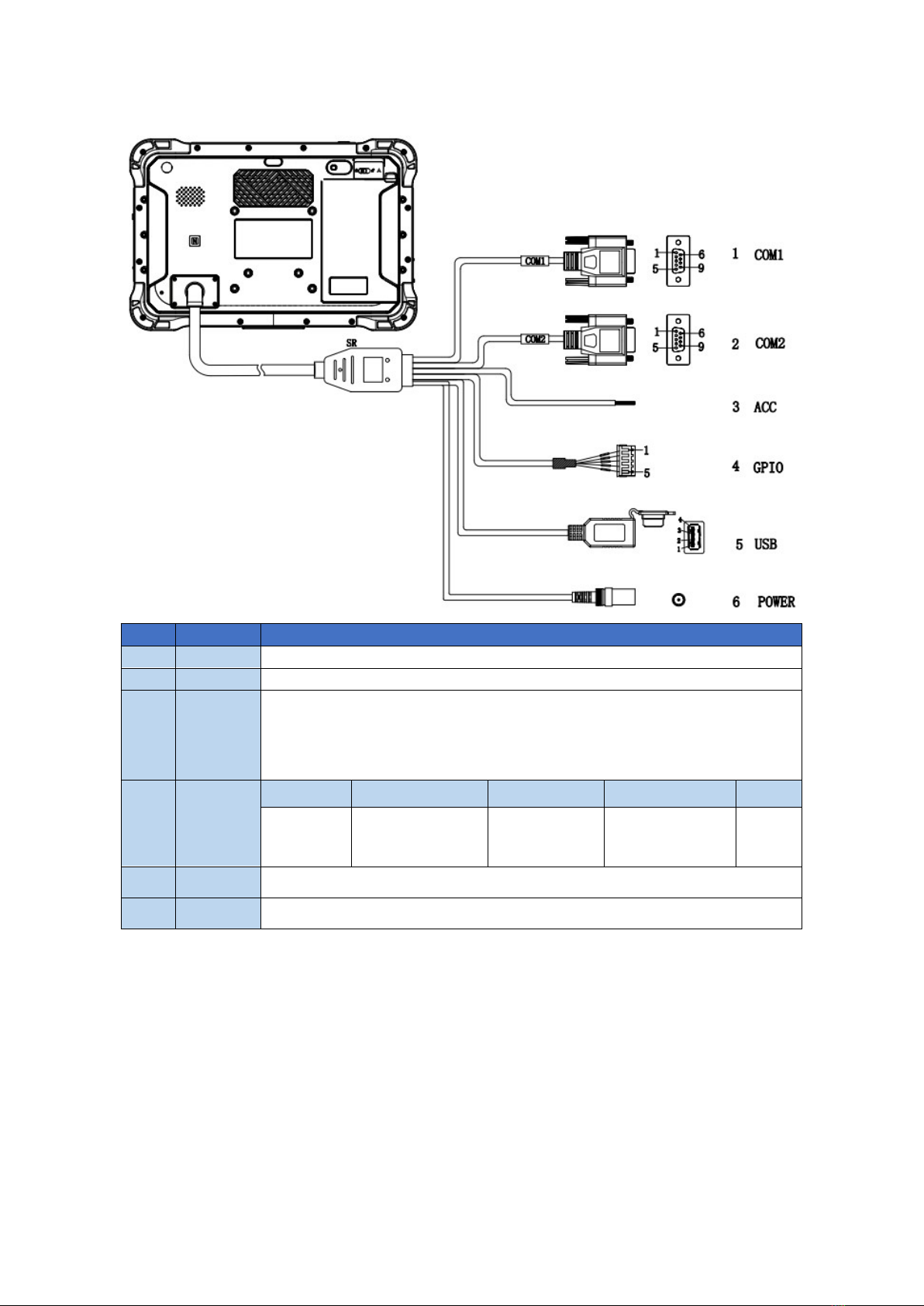
1.3 Extended Cable Definition
1.3.1 Docking Station
NO. Item Definition
1 COM 1 RS232 /dev/ttyHSL0.
2 COM 2 RS232 /dev/ttyHSL1.
3 ACC
Input
Connect with vehicle ACC power.
Voltage range: 0-30 V.
Note: With ACC function, the device is requested to connect the power
source via DC adaptor simultaneously to power on after ignition. please
refer to 3.3 for the DEMO and source code of ACC.
4
Power
DC input Voltage: DC 8-36 V (ISO 7637-2 compliant)
5 GPIO 1 2 3 4 5
Input 1 Input 2 Output 1 Output 2 GND
6 USB USB Type-A (can’t be used simultaneously with USB Type-C on the
device)
3
1.3.2 All in one cable
NO.
Item
Definition
1 COM 1 RS232 /dev/ttyHSL0.
2 COM 2 RS232 /dev/ttyHSL1.
3 ACC Connect with vehicle ACC power.
Voltage range: 0-30 V.
Note: With ACC function, the device is requested to connect the power
source via DC adaptor simultaneously to power on after ignition. please
refer to 3.3 for the DEMO and source code of ACC.
4 GPIO 1 2 3 4 5
Input 1 Input 2 Output 1 Output 2 GND
5 USB USB Type-A (can’t be used simultaneously with USB Type-C on the device)
6 Power DC input Voltage: DC 8-36 V (ISO 7637-2 compliant)

4
1.4 Specifications
Specifications
CPU Qualcomm Cortex-A53 64-bit
Octa-core processor 1.8 GHz
GPU Adreno 506
Operating
System Android 9.0
RAM 2GB LPDDR3(Default)/4GB(Optional)
Storage 16GB eMMC (Default)/64GB(Optional)
Storage
Expansion Micro SD Card 128G
LCD 10 Inch Digital IPS Panel(1280 x 800)1000 cd/m²
Touchscreen Multi touch capacitive touchscreen supporting glove and rain mode
Audio
Integrated microphone
Integrated speaker 2W
3.5 mm stereo headphone jack
Camera
(optional)
Front: 5.0megapixel camera
Rear: 16.0megapixel camera
Bluetooth
2402 MHz~2480 MHz
Integrated Bluetooth 4.2 LE + EDR class 2, with HID, A2DP, AVRCP,
BIP, BPP, FTP, HFP, HSP, OPP, SPP supported
WLAN
802.11 a/b/g/n/ac
2.4 GHz&5 GHz
Support Wake-on-WLAN (WoWLAN)
Support ad hoc mode
Support WAPI SMS4 hardware encryption
Support AP mode
Support Wi-Fi Direct
Support MCS 0-7 for HT20 and HT40
WWAN
US Version
North America
LTE FDD:
B2/B4/B5/B7/B12/B13/B14/B17/B25/
B26/B66/B71
LTE TDD: B41
WCDMA: B2/B4/B5
EU Version
EMEA/Korea/Thailand
LTE FDD:
B1/B2/B3/B4/B5/B7/B8/B20/B28
LTE TDD: B38/B39/B40/B41
WCDMA: B1/B2/B4/B5/B8
GSM: 850/900/1800/1900MHz
Data
Transmission
LTE
Cat 6 FDD: Max 300 Mbps (DL)/Max
50Mbps (UL)
Cat 6 TDD: Max 265 Mbps (DL)/Max
35Mbps (UL)
UMTS DC-USDPA: Max 42 Mbps (DL)

5
DC-HSUPA: Max 11.2 Mbps (UL)
WCDMA: Max 384 Kbps (DL/UL)
GNSS
GPS 1575.42 MHz±1.023 MHz
GLONASS 1597.5 MHz~1605.8 MHz
BeiDou 1561.098 MHz±2.046 MHz
NFC (optional)
Read/ write Made: ISO/IEC 14443 A&B up to 848 Kbit/s, Felica at
212&424 Kbit/s
MIFARE 1K, 4K, NFC Forum type 1, 2, 3,4,5 tags. ISO/IEC 15693
All peer-to-peer modes
Card Emulation Mode (from host): NFC Forum T4T (ISO/IEC 14443
A&B) at 106 Kbit/s; T3T Felica
Sound Build-in speak 2W,85 dB
Interfaces
Type-C,Compliant with USB 3.0(For data transfer support OTG )
Docking connector x1(pogo pin ×24)
3.5 mm headphone jack
1D/2D scanner
(optional)
All major 1D barcodes; PDF417、QR Code M1/M2/Micro and Data
Matrix etc.
Fingerprint
(optional) Capacitive, area sensor
Sensor Acceleration sensors,Ambient light sensor,Gyroscope,Compass
Power
DC 8-36 V(ISO 7637-II compliant)
Battery 3.7V,8000 mAh Li-ion (Replaceable)
Battery Operating time about 4 hours(typical)
Battery charging time about 6 hours
Physical
Dimensions 277×185×31.6 mm
Weight 1357 g
Environment
Gravity drop resistance test: 150 cm
Vibration test: MIL-STD-810G
Dust resistance test: IP6×
Water resistance test: IP×7
Operating temperature: -10℃~65℃/ 0℃~55℃(charging)
Storage temperature:-20℃~70℃
Docking Station All in one Cable
USB2.0(type-A) ×1×1
RS232 ×2×2
Docking Station
Status ×1×1
ACC ×1×1
power ×1×1
CANBUS CAN 2.0 b(optional)CAN 2.0 b(optional)
J1939(optional) J1939(optional)
6
OBD-II (optional) OBD-II (optional)
GPIO (Positive
Trigger input)
Input ×2, Output ×2
(Default)
GPIO ×6 (optional)
Input ×2, Output ×2 (Default)
GPIO ×6 (optional)
Analog Inputs ×3(optional) ×3(optional)
1-wire optional optional
RJ45 optional optional
RS485 optional optional
RS422 optional optional
Video in optional optional
Mounting (optional)
RAM Mount 1.912 Inch RAM mount compatible (AMPS holes)
VESA Bracket VESA 75 mm Folder Bracket
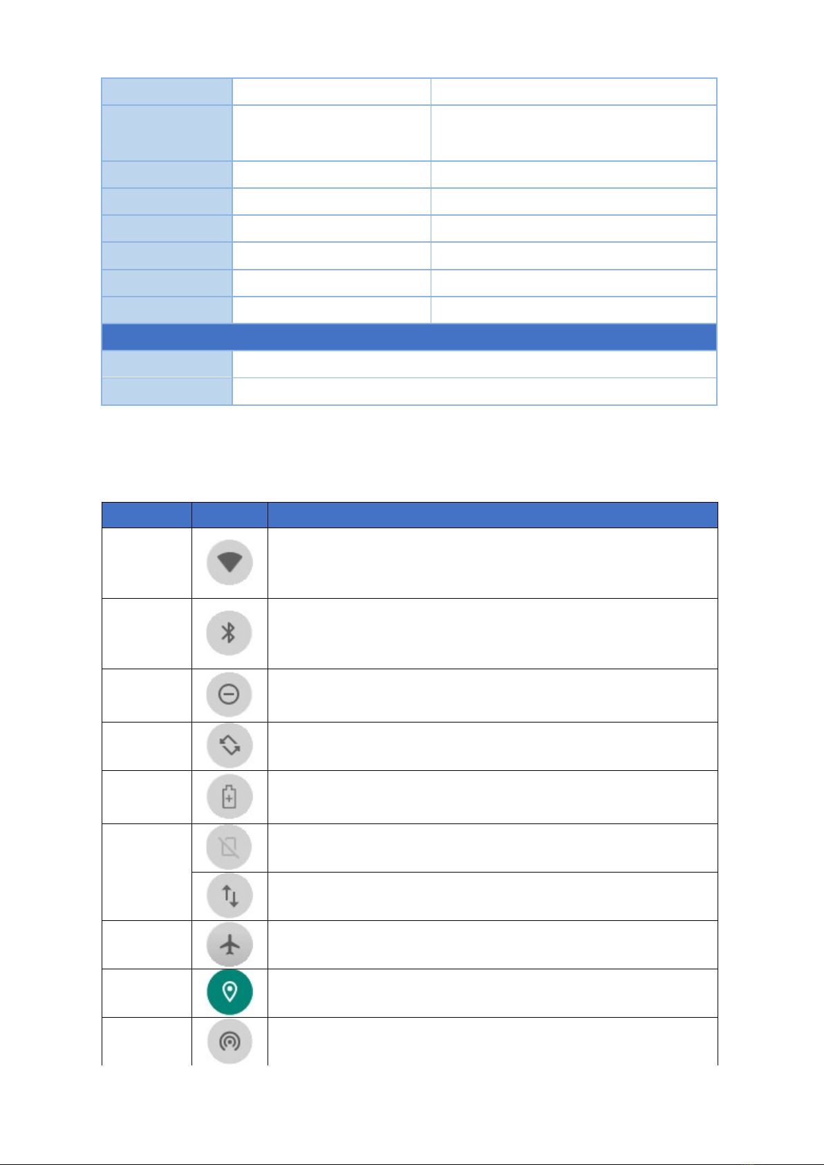
1.5 System icon description
Name Icon Description
WLAN
Long press to enter the setting interface to select a network that
can be connected and connect.
The number of display signal bars indicates the connection
signal
and
the
signal
strength.
Bluetooth
Long press to open the display Bluetooth settings, select the
Bluetooth name of the device you want to transfer to connect,
after the connection is successful, you can send and transfer
files.
Do not
disturb
Turn it on and enter Do Not Disturb mode.
The product is in a silent state, no notification is displayed, and
no notification sound is emitted.
Automatic
rotation
Choose whether the device is a fixed interface or an auto-
rotating interface.
Power
saving
mode
Power saving mode can only be turned on when using battery
power
Cellular
Data
No SIM card status.
Mobile signal connection status.
Flight
mode
When the airplane mode is on, you cannot use phones, the
Internet, and Bluetooth devices.
position GPS is currently working
Hot spot Start the Wi-Fi hotspot and it can be used as a WIFI transmitter.

7
Chapter 2 Getting Started
2.1 Power On/Off and Sleep/Wake
This Chapter is describing how to power on/off the device, put the device into
sleep mode (screen saver) and force restart.
Proper operation of power on/off the device will be beneficial to ensure the stability
of the system. The device status indicated by the color of the indicator is as
described in the following table for the standard VT-10 Pro. We provide
customized service if the customer has other requirements regarding the operation
of switch.
Indicator color
Device Status
Charging and Discharging Power On/Off
Green light on Uncharged or Full charged Power on
Red light on Charging Power off or Power on
Red or Green light
blinking
The device is abnormal, please cut off the external power
supply immediately and return it back to the factory for
repair.
2.1.1 Power on the Device
1. Power on by pressing the button:
Long press the power button for more than 2 seconds until the boot screen
displayed. It needs around 25 seconds to start the system. The indicator is on
when VT-10 Pro activate normally.
2. Power on by connecting ACC, see the details in Chapter “3.3 Using ACC”.
3. Power consumption during operation:9.6W(typical)
2.1.2 Power off the Device
1. Power off by pressing the button: In the status of working on the device
desktop, long press the power button for more than 2 seconds until the
shutdown prompt pop-up then click the “POWER OFF”option.
2. Power off by ACC, see the details in the Chapter “3.3 Using ACC”.
3. Remark: In order to reduce the standby power consumption, the red light is on
in charging status when power on. And the light will go off if full charged.
4. The consumption during power off :0 W
2.1.3 Sleep and Wake the Device
a. Auto sleep, the sleep time can be set up in the settings.
flashlight Can turn on the flashlight function
8
b. Short press button to sleep.
c. Sleep by ACC, see the details in Chapter “3.3 Using ACC”
d. Short press to wake
e. Wake by ACC, see the details in Chapter “3.3 Using ACC”
f. The average of power consumption in sleep status: 1W
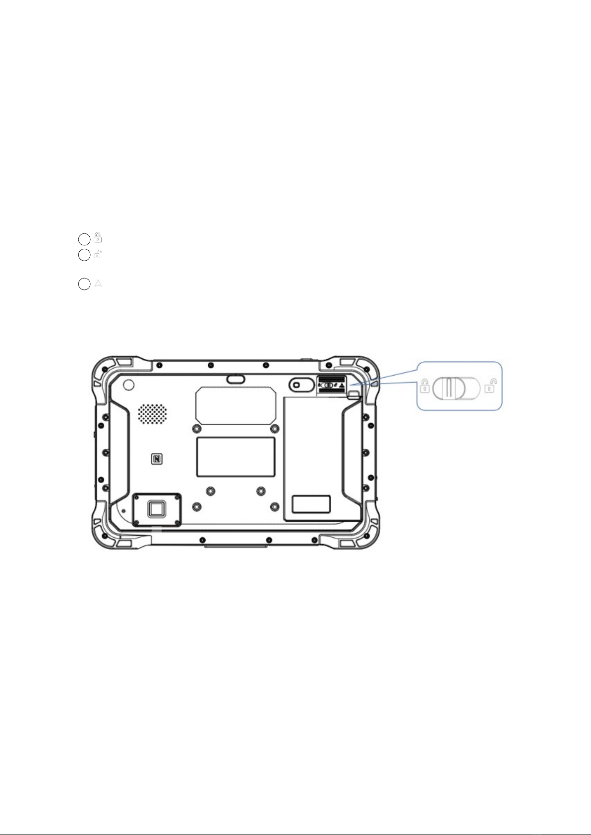
2.2 Changing the Battery
The tablet battery is installed in a removable way, which greatly facilitates the
user's use of disassembly and installation.
(Note: Please shut down before removing the battery.)
Icon introduction:
1:The switch is on the left, lock the machine state, lock the battery
2:The switch is on the right to unlock the machine status, and the battery can
be removed
3:In the direction of the arrow, push the indicated skateboard up
The specific operation methods of installation and removal are as follows:
①To lock the battery status switch, turn it to the left. When you want to remove the
battery, you need to turn the switch to the right.
②Slide the control battery back plate up along the groove. After completion, the
slide plate is on the top, as shown in the figure below.

9
③Pull out the fixed battery groove (located on the upper right of the battery).
④After completing the above operations, as shown in the figure below.

10
In order to ensure the life and performance of the battery, if your tablet has been
stored in the warehouse for more than three months, it is recommended to charge
the battery every three months.
2.2.1 Charging with the Power Adapter
A. Use a 12V power adapter to directly connect the charging port on the tablet to
charge.
B. The machine with a docking station or integrated cable can also be charged
through the power input on the tail cable. Detailed reference(1.3 Extended Cable
Definition )
Warning:
Please ensure that the input voltage of the DC interface is within the range of 8V-
36V, or use the 12V adapter coming with device. If the input voltage of the DC is
outside this range, the VT-10 Pro may be unable to charge or damaged. It may
cause the warranty invalid.
2.2.2 Checking the Battery Level
a. When the charging is in process, a battery indicator will appear in the status bar
showing the charging percentage. To view the charge percentage, swipe down the
Status Bar and you will see the charging percentage.
b. When the battery is fully charged, you can disconnect the DC input. If available,
please keep the device in charging by DC power supply. See the details in “2.3
Charging the Battery”.
2.3 Optimizing Battery Life
If the VT-10 Pro is unable to keep charging by DC power supply, to optimize the
operating time of the battery, it is recommended that you do the following:
Decrease the LCD display brightness.
Set a shorter timeout of inactivity to allow the screen enter sleep mode.
Turn off the display if you are not using it.
Turn off Wi-Fi, Bluetooth or GPS function if you are not using it.
Turn off the App that heavily drains the battery if you are not using it. To view
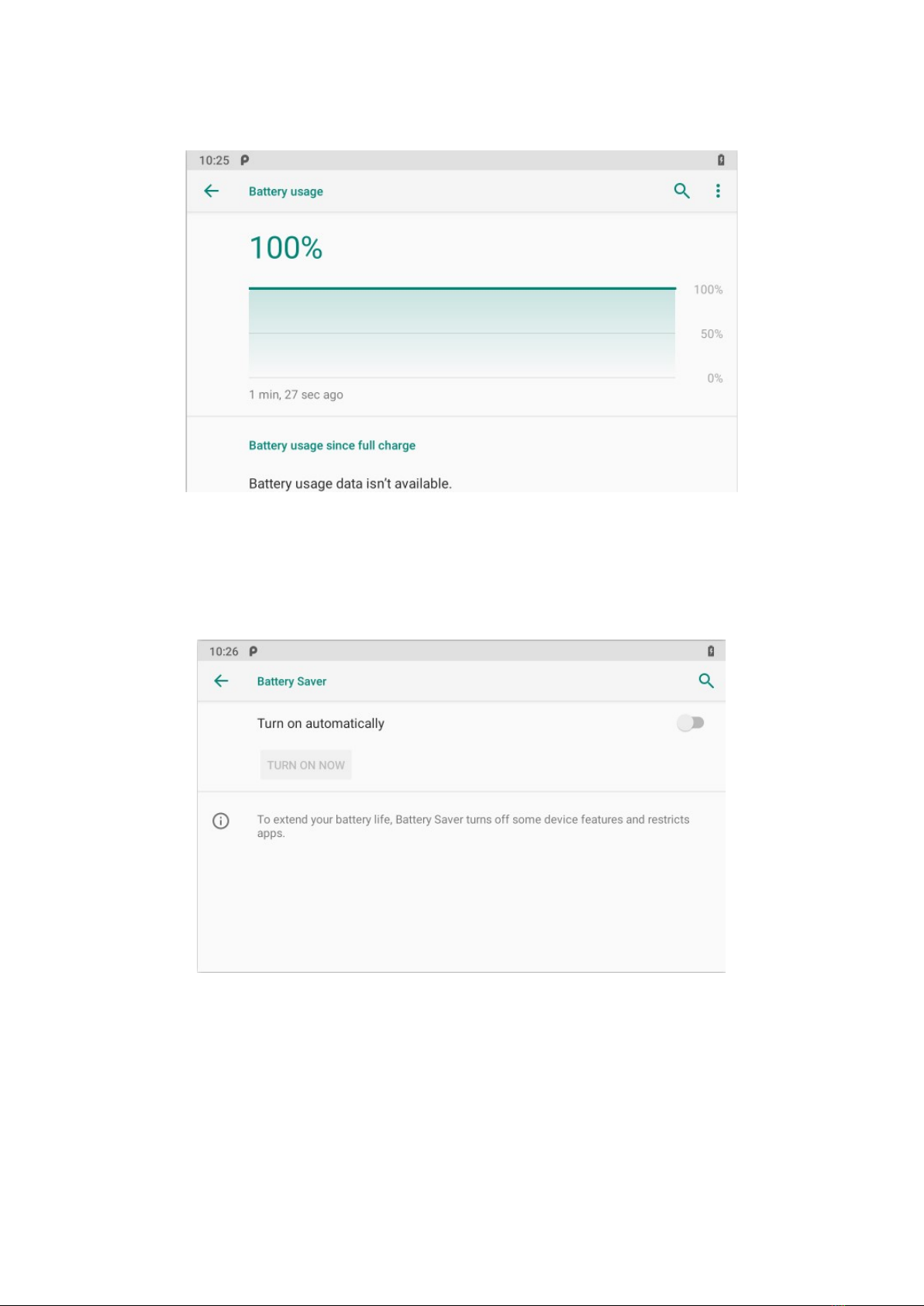
11
the battery usage by individual App, swipe down the Status Bar in the upper
right corner and tap and hold the Battery icon.
Enable CPU power saving mode on battery settings page to limit the
maximum CPU performance to conserve battery life and lower device
temperature.
To access the battery settings page, swipe down the Status Bar in the
upper right corner and then tap and hold the Battery icon.
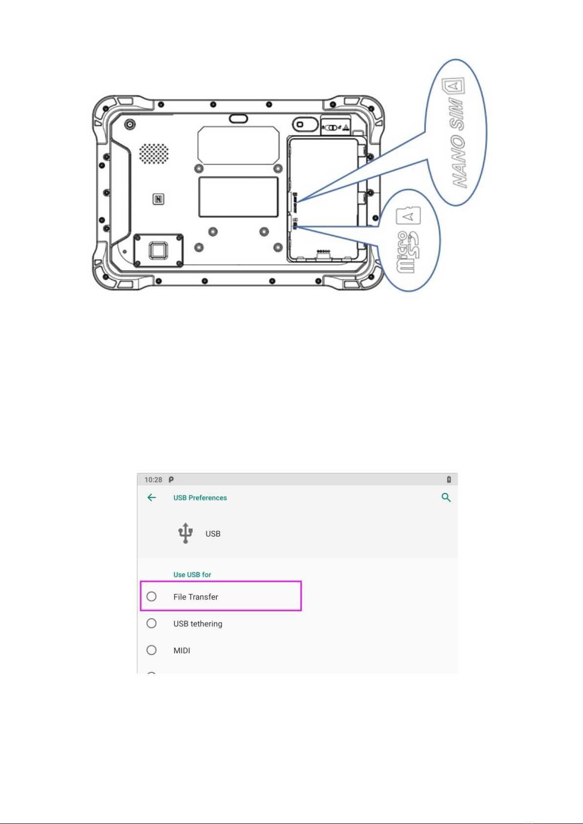
2.4 Installing Micro SD and SIM Card
Before installing the SIM card and TF, you need to remove the tablet battery. After
disassembly, please insert the required card into the machine in the direction indicated in the
figure below. Finally, load the battery and press the power button to start the machine.
12
Chapter 3 Using VT-10 Pro Hardware Interface
3.1 Transferring Files between Computer and the Device
You can transfer files, such as pictures or audio files, between your computer
and your device using the provided USB cable.
3.1.1 Connection
Connect the device to the computer by using the USB type-c cable, and open
the prompt message of the device. Select “File Transfer”.

13
Find out the “Device”in “This PC”.
3.2 Using Serial Port Demo App
Serial Port ID: COM1, COM2
Correspondence between RS232 tail line and device node.
COM1=/dev/ttyHSL0.
COM2=/dev/ttyHSL1.
1. The boxes in red means the text box for the COM port information received, to
display information received by corresponding COM port.
2. The boxes in red means the text input box for the COM port information sent,
to edit information sent by corresponding COM port.
3. The left box in red means Baud rate Drop-down selection box, to select
corresponding COM port Baud rate.
4. The right box in red means COM port switch, to switch on/off corresponding
COM port.
5. The boxes in red means auto send interval time setting.
6. The boxes in red means auto send mode selection, and COM port info.
sending button.
7. COM port info. sending button.
8. The boxes in red means text rows counting in the information receiving text
box, the above numbers corresponding to the COM port information receiving
box on the left, the following numbers corresponding to the one on the right.
9. The boxes in red means send/receive information codec format option button,
select “Txt” to send info. with String code, select Hex to send info. with
Hexadecimal format code.
14
10. The boxes in red means manual clear button, click to clear both info. in the
COM port info. receiving boxes.
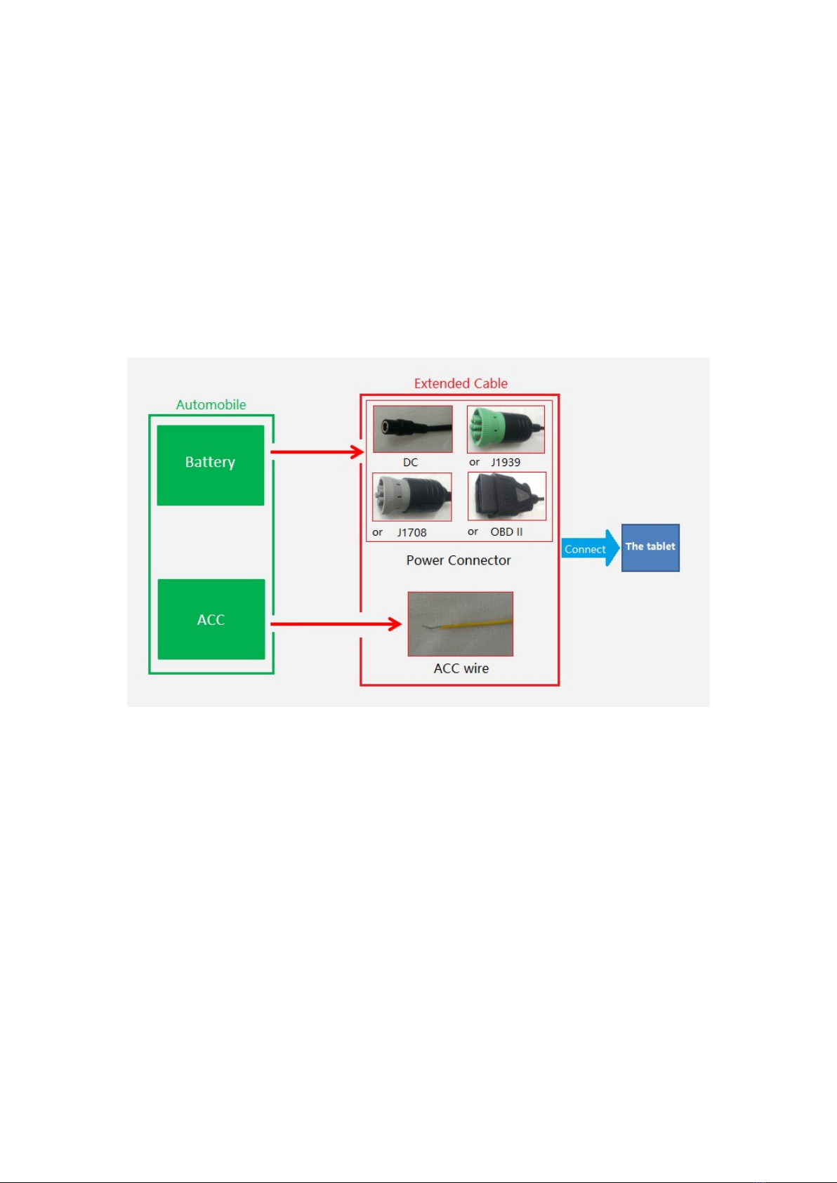
3.3 Using ACC
Please see “1.3 Extended cable definition” for ACC Interface details.
3.3.1 ACC Connection Instruction
Figure, connecting the tablet with vehicle power supply through extended cable
or docking station, and connecting ACC wire on extended cable of the tablet
with ACC of vehicle.
3.3.2 ACC Functions
I. Power on the tablet by ACC.
II. Light up the screen by ACC.
III. To turn off the screen by ACC trigger based upon the setting delayed time.
IV. To shut down the tablet by ACC trigger based upon the setting delayed time.
Note:
a) The ACC is triggered by the electric level.
b) Function of “Power on the tablet by ACC” can’t be modified from the system.
c) It takes about 10 seconds to completely shut down the system after ACC is
started. Please do not try to use boot-triggered actions during this process.
Table of contents
Other 3Rtablet GPS manuals


