3Rtablet VT-7 Pro User manual

VT-7 Pro
7Inch Rugged Android Vehicle Display Terminal
User Manual
Version 1.0

Revision History
Version
Release Time
Description
1.0
202006
Initial Release
Copyright
Copyright © 3Rtablet Corp. All Rights Reserved.
This document contains proprietary information protected by copyright. No part
of this manual may be reproduced by any mechanical, electronic, or other
means in any form without prior written permission of the manufacturer.
Disclaimer
The information in this document is subject to change without prior notice in
order to improve the reliability, design and function. It does not represent a com-
mitment on the part of the manufacturer.
Under no circumstances will the manufacturer be liable for any direct, indirect,
special, incidental, or consequential damages arising from the use or inability
to use the product or documentation, even if advised of the possibility of such
damages.
About This Manual
This user’s manual provides the general information and installation instructions
for the product. The manual is meant for the experienced users and integrators
with hardware knowledge of personal computers. If you are not sure about any
description in this manual, consult your vendor before further handling.
We recommend that you keep one copy of this manual for the quick reference
for any necessary maintenance in the future. Thank you for choosing 3RTablet
products.

CONTENT
Chapter 1: Introduction ........................................................................................................7
1.1 Product Highlights ..................................................................................................7
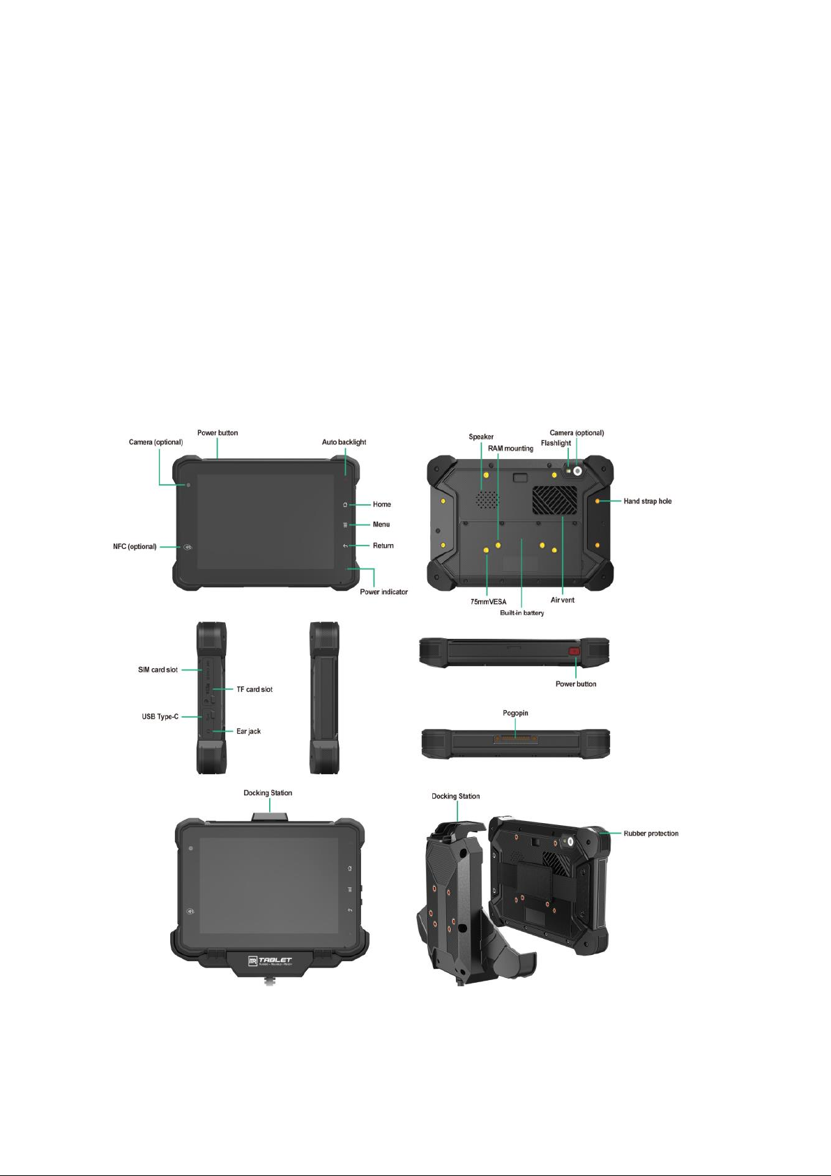
1.2 Parts of the Device .................................................................................................7
1.3 Extended Cable Definition......................................................................................8
1.3.1 Standard Version..........................................................................................8
1.3.2 OBD-II Version .............................................................................................9
1.3.3 SAE J1939 Version ....................................................................................10
1.3.4 CAN Bus Version .......................................................................................11
1.4 Specifications .......................................................................................................12
Chapter 2: Getting Started.................................................................................................15
2.1 Power On/Off and Sleep/Wake ............................................................................15
2.1.1 Power on the Device .........................................................................................15
2.1.2 Power off the Device ..................................................................................15
2.1.3 Sleep and Wake the Device.......................................................................15
2.2 Installing Micro SD and SIM Card ........................................................................16
2.3 Charging the Battery ............................................................................................16
2.3.1 Charging with the Power Adapter ..............................................................17
2.3.2 Checking the Battery Level ........................................................................17
2.3.3 Installing/Replacing the Battery .................................................................18
2.4 Optimizing Battery Life .........................................................................................19
Chapter 3. Using VT-7 Pro Hardware Interface.................................................................21
3.1 Transferring Files between Computer and the Device.........................................21
3.1.1 Connection .................................................................................................21
3.2 Using Serial Port Demo App.................................................................................23
3.3 Using ACC ............................................................................................................24
3.3.1 ACC Connection Instruction......................................................................24
3.3.2 ACC Functions ..........................................................................................24
3.3.3 ACC Settings Path ....................................................................................25
3.3.4 ACC Settings.............................................................................................26
3.4 Using GPIO ..........................................................................................................27
3.3.1 GPIO Tail Lines Instruction .......................................................................27
3.3.2 GPIO Typical Connection..........................................................................27
3.3.3 GPIO Specification....................................................................................28
3.3.4 GPIO_DEMO Instruction...........................................................................28
3.5 Using NFC Function .............................................................................................31
3.5.1 NFC Activation Method ..............................................................................31
3.5.2 NFC Usage Demo......................................................................................32
3.6 System Root Switch Usage Guide .......................................................................34
3.7 OBD-II Interface (optional) ...................................................................................35
3.8 J1939 Interface (optional).....................................................................................36
3.9 CAN Bus Interface (optional)................................................................................37
Chapter 4. Docking Station Using Instruction ...........................................................37
Chapter 5 . Accessories..............................................................................................40

Declaration of Conformity
CE
The CE symbol on your product indicates that it is in compliance with the di-
rectives of the Union European (EU). A Certificate of Compliance is available
by contacting Technical Support.
This product has passed the CE test for environmental specifications when
shielded cables are used for external wiring. We recommend the use of
shielded cables.
FCC Class B
This device complies with Part 15 of the FCC Rules. Any changes or modifica-
tions not expressly approved by the guarantee of this device could void the
user’s authority to operate the equipment.
RoHS
3RTablet Corp. certifies that all components in its products are in compliance
and conform to the European Union’s Restriction of Use of Hazardous Sub-
stances in Electrical and Electronic Equipment (RoHS) Directive 2002/95/EC.
Safety Symbols
This symbol of “CAUTION” indicates that there is a danger of injury
to the user or a risk of damage to the product, should warning no-
tices be disregarded.
Battery Recycle
This symbol indicates electrical warning.
Important Safety Instructions
Read these safety instructions carefully:
► Read all cautions and warnings on the equipment.
► Place this equipment on a reliable surface when installing. Dropping it or
letting it fall may cause damage.
► Make sure the correct voltage is connected to the equipment.
► For pluggable equipment, the socket outlet should be near the equipment
and should be easily accessible.
► Keep this equipment away from humidity.
► Disconnect this equipment from the A/C outlet before cleaning it. Use a
moist cloth. Do not use liquid or sprayed detergent for cleaning.
► Do not scratch or rub the screen with a hard object.
► Never use any of the solvents, such as Thinner Spray-type cleaner, Wax,
Benzene, Abrasive cleaner, Acid or Alkaline solvent, on the display. Harsh
chemicals may cause damage to the cabinet and the touch sensor.
► Remove the dirt with a lightly moistened cloth and a mild solvent detergent.

Then wipe the cabinet with a soft dry cloth.
► If the equipment will not be used for a long time, disconnect it from the
power source to avoid damage by transient over voltage.
► Never pour any liquid into openings. This may cause fire or electrical
shock.
► If one of the following situations arises, get the equipment checked by ser-
vice personnel:
a. The power cord or plug is damaged.
b. Liquid has penetrated into the equipment.
c. The equipment has been exposed to moisture.
d. The equipment does not work well, or you cannot get it to work according
to the user’s manual.
e. The equipment has been dropped or damaged.
f. The equipment has obvious signs of breakage.
Rechargeable Battery Pack Safety
With very little care, you can optimize the battery life and maximize the
lifespan of the battery. Most importantly, use only the equipment in its ideal
operating temperature (as described in 1.4 Specifications) – do not leave it in
a hot trunk during the summer.
•Using the Equipment for the First Time
Be sure to fully charge (approx. 4 hours) the equipment when charging the
equipment for the first time.
•Long-Term Storage & Maintenance
If you are putting away the battery for more than three months, it is recom-
mended that the battery should be stored separately and fully charged,
and get recharged every three months. If you store an uncharged battery,
it could fall into a deep worn-out state which would render it incapable of
holding any charge. Be sure to store the equipment and battery at the
proper temperature (as described in 1.5 Specifications).
Additional Information & Technical Support
You can download the related technical documents such as data sheet and
user’s manual as well as driver on our website.
Please do not hesitate to call or e-mail our customer service when you still
cannot get the information you need. www.3Rtablet.com
Warranty
This product is warranted to be in good working order during the warranty pe-
riod. Should this product fail to be in good working order at any time during
this period, we will, at our option, replace or repair it according to 3Rtablet af-
ter-sale-service terms. This warranty does not apply to products damaged by
misuse, modifications, accident or disaster.

Vendor assumes no liability for any damages, lost profits, lost savings or any
other incidental or consequential damage resulting from the use, misuse of, or
inability to use this product. Vendor will not be liable for any claim made by
any other related party.
Return authorization must be obtained from the vendor before returned mer-
chandise will be accepted. Authorization can be obtained by calling or email-
ing the account representative from vendor and requesting a Return Merchan-
dise Authorization (RMA) number. Returned goods should always be accom-
panied by a clear problem description.
Chapter 1: Introduction
1.1 Product Highlights
● Qualcomm Cortex-A53 64-bit Octa-core processor 1.8G
● Android 9.0 Operation System
● Comply with IP67 rating
● WIFI, Bluetooth, LTE, GNSS and 5000mAh rechargeable battery supported
● 7 Inch IPS Display, physical 1280x800 resolution, 800cd/m², multi-point capaci-
tive touch
● Portable with Docking Station
1.2 Parts of the Device
1.3 Extended Cable Definition
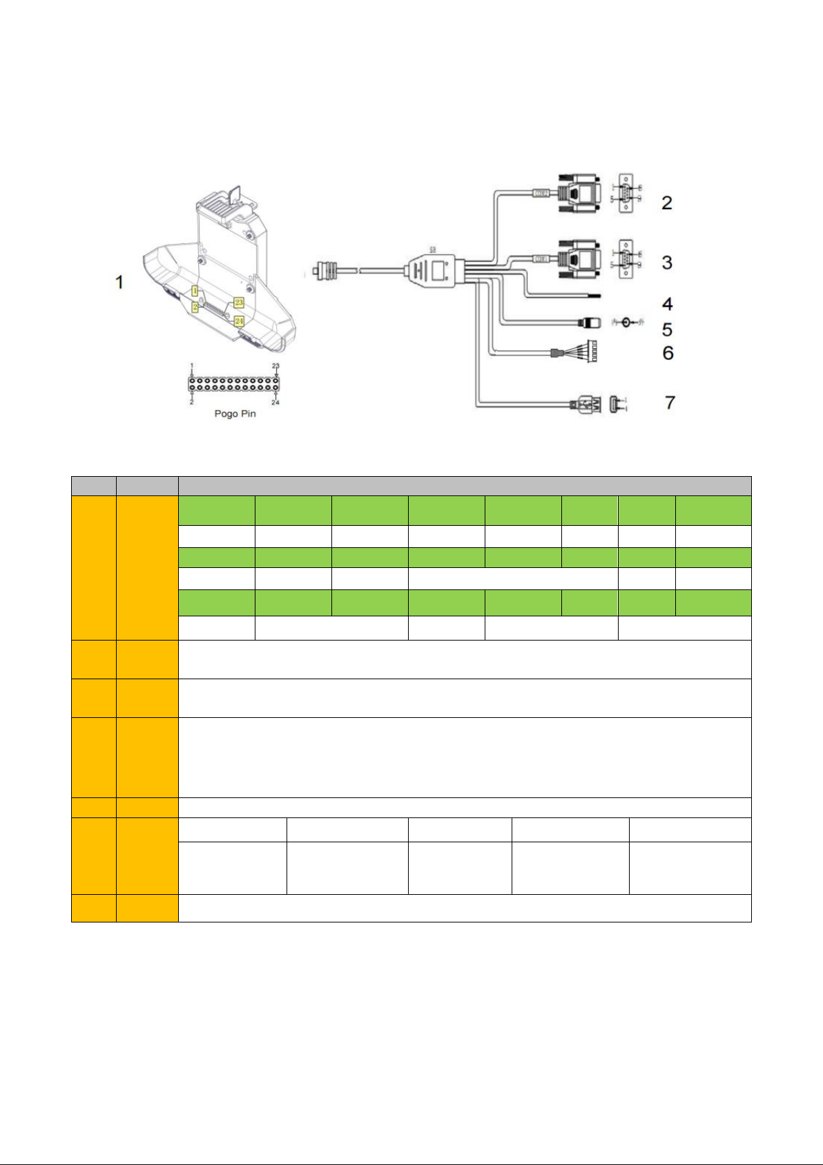
1.3.1 Standard Version
NO.
Item
Definition
1
Pogo
Pin
1
2
3
4
5
6
7
8
GPIO69
GPIO33
GPIO66
GPIO22
GPIO23
ACC
GND
RXD0
9
10
11
12
13
14
15
16
TXD0
RXD1
TXD1
GND
ID
DP
17
18
19
20
21
22
23
24
DM
VUSB
EN
DC+
DC-
2
COM
2
RS232 /dev/ttyHSL1.
3
COM
1
RS232 /dev/ttyHSL0.
4
ACC
Input
Connect with vehicle ACC power.
Voltage range: 0-30V.
Note: With ACC function, the device is requested to connect the power source via DC
adaptor simultaneously to power on after ignition. please refer to 3-2 for the DEMO and
source code of ACC.
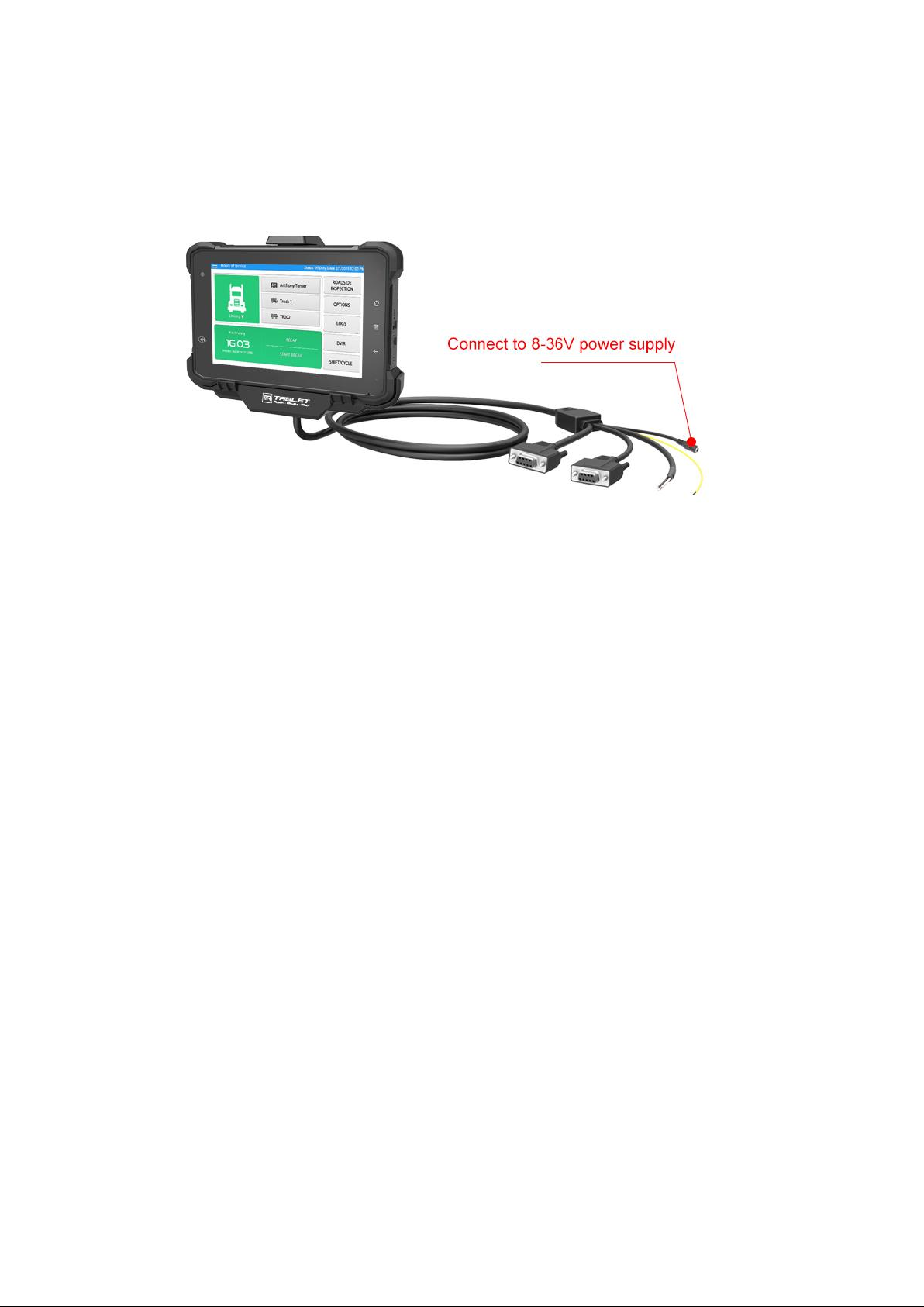
5
Power
DC input Voltage:DC8-36V(ISO 7637-2 compliant)
6
GPIO
Red
White
Green
Yellow
Black
Input 1
Input 2
Output 3
Output 4
GND
7
USB
USB Type-A (can’t be used simultaneously with USB Type-C on the device)
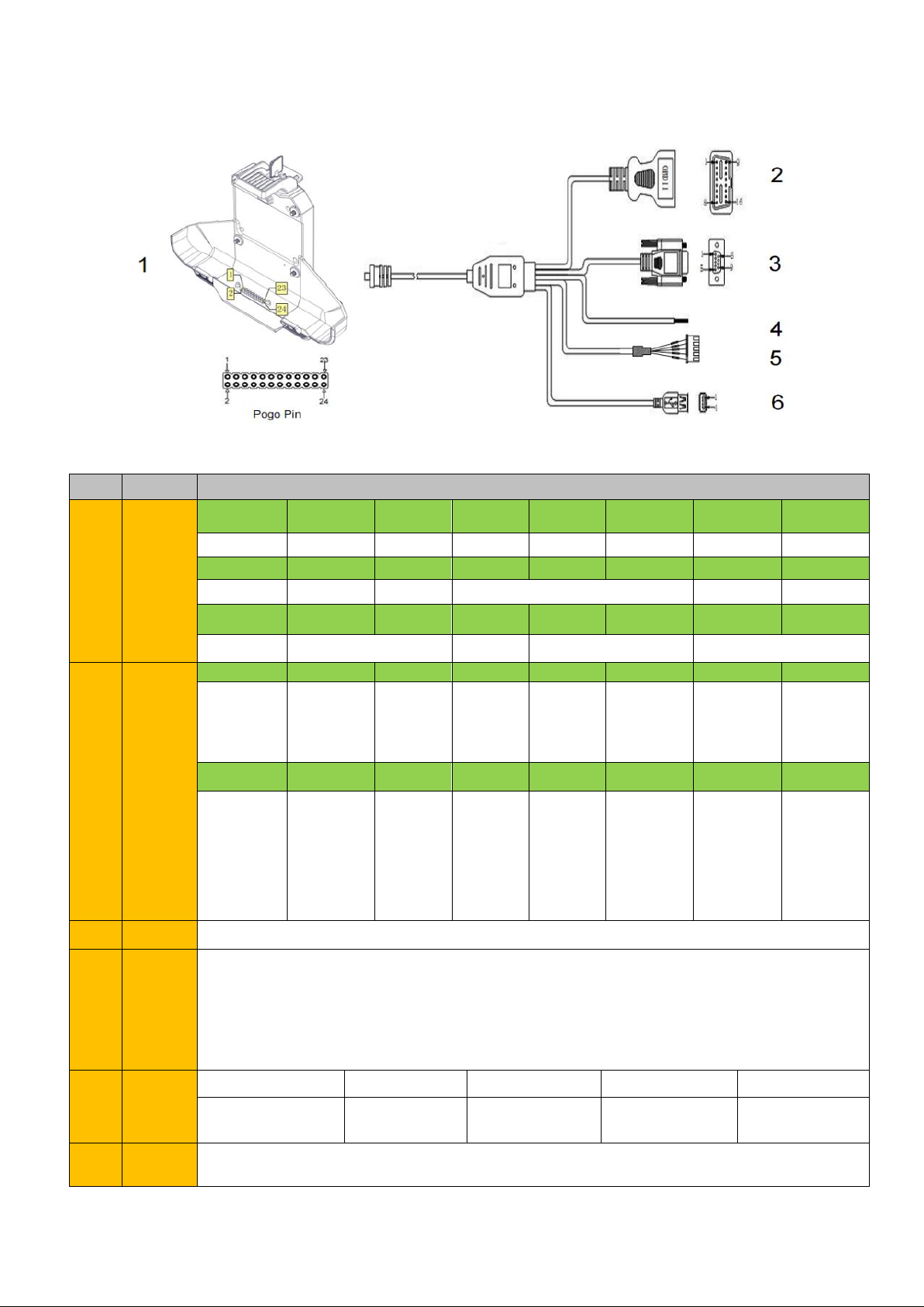
1.3.2 OBD-II Version
NO.
Item
Definition
1
Pogo
Pin
1
2
3
4
5
6
7
8
GPIO69
GPIO33
GPIO66
GPIO22
GPIO23
ACC
GND
RXD0
9
10
11
12
13
14
15
16
TXD0
RXD1
TXD1
GND
ID
DP
17
18
19
20
21
22
23
24
DM
VUSB
EN
DC+
DC-
2
OBD-II
1
2
3
4
5
6
7
8
Reserved
Bus posi-
tive line of
SAE J1850
Reserved
Chassis
ground
Signal
ground
CAN_H
line of ISO
15765-4
K_line ac-
cording to
ISO 9141-
2 and ISO
14230-4
Reserved
9
10
11
12
13
14
15
16
Reserved
Bus nega-
tive line of
SAE J1850
Reserved
Reserved
Reserved
CAN_L line
of ISO
15765-4
L_line ac-
cording to
ISO 9141-
2 and ISO
14230-4
Permanent
positive
voltage
3
COM
RS232 /dev/ttyHSL0.
4
ACC
input
Connect with vehicle ACC power.
Voltage range: 0-30V.
Note: With ACC function, the device is requested to connect the power source via DC
adaptor simultaneously to power on after ignition. please refer to 3-2 for the DEMO and
source code of ACC.
5
GPIO
Red
White
Green
Yellow
Black
Input 1
Input 2
Output 3
Output 4
GND
6
USB
USB Type-A(can not be used simultaneously with USB Type-C on the device)

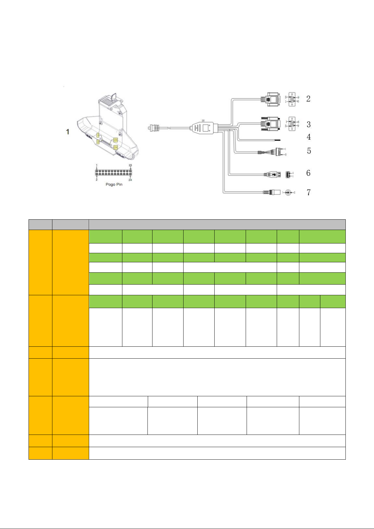
1.3.3 SAE J1939 Version
NO.
Item
Definition
1
Pogo
Pin
1
2
3
4
5
6
7
8
GPIO69
GPIO33
GPIO66
GPIO22
GPIO23
ACC
GND
RXD0
9
10
11
12
13
14
15
16
TXD0
RXD1
TXD1
GND
ID
DP
17
18
19
20
21
22
23
24
DM
VUSB
EN
DC+
DC-
2
J1939
A
B
C
D
E
F
G
Battery
Minus
(Ground)
Battery
Plus
(+V)
CAN/
J1939
High
CAN/
J1939
Low
CAN/J1939
shield
Protocol
“High”Line,i.e
CAN/J1708/J193
9 High
Protocol
“Low”Line,i.e
CAN/J1708/J1939
Low
3
COM
RS232 /dev/ttyHSL0.
4
ACC
input
Connect with vehicle ACC power.
Voltage range: 0-30V.
Note: With ACC function, the device is requested to connect the power source via DC
adaptor simultaneously to power on after ignition. please refer to 3-2 for the DEMO and
source code of ACC.
5
GPIO
out-
put
Red
White
Green
Yellow
Black
Input 1
Input 2
Output 3
Output 4
GND
6
USB
USB Type-A (can’t be used simultaneously with USB Type-C on the device)
1.3.4 CAN Bus Version
NO.
Item
Definition
1
Pogo
Pin
1
2
3
4
5
6
7
8
GPIO69
GPIO33
GPIO66
GPIO22
GPIO23
ACC
GND
RXD0
9
10
11
12
13
14
15
16
TXD0
RXD1
TXD1
GND
ID
DP
17
18
19
20
21
22
23
24
DM
VUSB
EN
DC+
DC-
2
CAN
Bus
1
2
3
4
5
6
7
8
9
CAN
Low
Shielded
Line
CAN
High
3
COM
RS232 /dev/ttyHSL0.
4
ACC in-
put
Connect with vehicle ACC power.
Voltage range: 0-30V.
Note: With ACC function, the device is requested to connect the power source via DC
adaptor simultaneously to power on after ignition. please refer to 3-2 for the DEMO
and source code of ACC.
5
GPIO
Red
White
Green
Yellow
Black
Input 1
Input 2
Output 3
Output 4
GND
6
USB
USB Type-A (can’t be used simultaneously with USB Type-C on the device)
7
Power
DC input Voltage: DC8-36V (ISO 7637-2 compliant)

1.4 Specifications
Durability Features
IP67 Rating Certified
1.5m (5ft.) drop-resistance
Raised bezel for LCD impact protection
LCD Display
Size
7 Inch Digital IPS Panel
Resolution
1280 x 800
Brightness
800 cd/m²
Touch screen
Type
Multi-point Capacitive Touch
System
CPU
Qualcomm Cortex-A53 64-bit
Octa-core processor 1.8G
OS
Android 9.0
Memory
LPDDR3 2GB
Storage
16GB
GPU
Adreno 506
Audio
Integrated microphone
Integrated speaker 2W
1 x 3.5mm stereo headphone jack
Navigation
AGPS & E-com-
pass
GPS
1575.42MHz±1.023MHz
GLONASS
1597.5MHz~1605.8MHz
BeiDou
1561.098MHz±2.046MHz
WWAN
US Version
North America
LTE FDD:
B2/B4/B5/B7/B12/B13/B14/B17/B25/
B26/B66/B71
LTE TDD: B41
WCDMA: B2/B4/B5
EU Version EMEA/Ko-
rea/Thailand
LTE FDD: B1/B2/B3/B4/B5/B7/B8/B20/B28
LTE TDD: B38/B39/B40/B41
WCDMA: B1/B2/B4/B5/B8
GSM: 850/900/1800/1900MHz
Data
Transmission
LTE
Cat 6 FDD: Max 300Mbps (DL)/Max 50Mbps
(UL)
Cat 6 TDD: Max 265Mbps (DL)/Max 35Mbps
(UL)
UMTS
DC-USDPA: Max 42Mbps (DL)
DC-HSUPA: Max 11.2Mbps (UL)
WCDMA: Max 384Kbps (DL/UL)
WLAN
802.11a/b/g/n/ac

2.4GHz&5GHz
Support Wake-on-WLAN (WoWLAN)
Support ad hoc mode
Support WAPI SMS4 hardware encryption
Support AP mode
Support Wi-Fi Direct
Support MCS 0-7 for HT20 and HT40
Bluetooth
2402MHz~2480MHz
Integrated Bluetooth 4.2 LE + EDR class 2, with HID, A2DP, AVRCP,
BIP, BPP, FTP, HFP, HSP, OPP, SPP supported
Sensor
Gyroscope
Accelerometer (G-sensor)
NFC (optional)
Read/ write Made: ISO/IEC 14443 A&B up to 848kbit/s, FeliCa at
212&424 kbit/s
MIFARE 1K, 4K, NFC Forum type 1, 2, 3,4,5 tags. ISO/IEC 15693
All peer-to-peer modes
Card Emulation Mode (from host): NFC Forum T4T (ISO/IEC 14443
A&B) at 106 kbit/s
Camera (op-
tional)
Front: 5.0megapixel camera
Rear: 16.0megapixel camera
Mounting (optional)
RAM Mount
1.912 Inch RAM mount compatible (AMPS holes)
VESA Bracket
VESA 75mm Folder Bracket
I/O Interface (standard)
Serial Port
2 x RS232
USB Port
1 x USB Host,1x USB Device, high speed up to 480Mbps
SD Slot
1 x Micro SD card, 1.8v / 2.95v, up to 128G
SIM Socket
1 x Micro SIM Card slot, 1.8v / 2.95v
GPIO
GPIO×2 Input, GPIO×2 Output (See “3. 4Extended Cable Definition” for
details.)
(See “3.3 Extended Cable Definition” for details.)
I/O Interface (CAN Bus version)
Serial Port
1 x RS232
CAN Bus
1 ×CAN Bus
USB Port
1 x USB Host,1x USB Device, High speed up to 480Mbps
SD Slot
1 x Micro SD card, 1.8v / 2.95v, up to 64G
SIM Socket
1 x Micro SIM Card slot, 1.8v / 2.95v

GPIO
GPIO×2 Input, GPIO×2 Output (See “3. 4Extended Cable Definition” for
details.)
ACC
(See “3. 3Extended Cable Definition” for details.)
I/O Interface (J1939 /OBD-II/CAN Bus version)
Serial Port
1 x RS232
J1939/OBD-
II/CAN Bus
(See “1.3Extended Cable Definition” for details.)
USB Port
1 x USB Host,1x USB Device, High speed up to 480Mbps
SD Slot
1 x Micro SD card, 1.8v / 2.95v, up to 64G
SIM Socket
1 x Micro SIM Card slot, 1.8v / 2.95v
GPIO
GPIO×2 Input, GPIO×2 Output (See “3. 4Extended Cable Definition” for
details.)
ACC
(See “3. 3Extended Cable Definition” for details.)
Power Supply
Power System
External AC Power Adapter
Battery Type
Lithium-ion rechargeable battery
Field replaceable (for maintenance)
Battery Capac-
ity
3.7V, 5000mAh battery (Typically around 5hours)
Power Con-
sumption
Normal mode: 5W
Charging mode: 8W
Adapter Input
AC 100-240C, 50-60Hz
Adapter Output
DC power output 12V/2A
Mechanical & Environmental
Operating
Temp.
-10°C ~ 65°C (14°F ~ 149°F)
Storage Temp.
-20°C ~ 70°C (-4°F ~ 158°F)
Operating
95% (non-condensing)
Humidity
Dimensions
207.4 x 137.4 x 30.1 mm
(W x H x D)
Weight
Tablet:815g
Docking station:550g

Chapter 2: Getting Started
2.1 Power On/Off and Sleep/Wake
This Chapter is describing how to power on/off the device, put the device into
sleep mode (screen saver) and force restart.
Proper operation of power on/off the device will be beneficial to ensure the stability
of the system. The device status indicated by the color of the indicator is as de-
scribed in the following table for the standard VT-7 Pro. We provide customized
service if the customer has other requirements regarding the operation of switch.
Table 2.1.1 VT-7 Pro Indicator color and device status table
Indicator color
Device Status
Charging and Discharging
Power On/Off
Green light on
Uncharged or Full charged
Power on
Red light on
Charging
Power off or Power on
Red or Green light blink-
ing
The device is abnormal, please cut off the external power
supply immediately and return it back to the factory for re-
pair.
2.1.1 Power on the Device
1. Power on by pressing the button:
Long press the power button for more than 2 seconds until the boot screen dis-
played. It needs around 40 seconds to start the system. The indicator is on
when VT-7 Pro activate normally.
2. Power on by connecting ACC, see the details in Chapter “3.3 Using ACC”.
3. Power consumption during operation:5w (typical)
2.1.2 Power off the Device
1. Power off by pressing the button: In the status of working on the device desk-
top, long press the power button for more than 2 seconds until the shutdown
prompt pop-up then click the “POWER OFF” option.
2. Power off by ACC, see the details in the Chapter “3.3 Using ACC”.
3. Remark: In order to reduce the standby power consumption, the red light is on
in charging status when power on. And the light will go off if full charged.
4. The consumption during power off (with docking station): around 100mW.
2.1.3 Sleep and Wake the Device
a. Auto sleep, the sleep time can be set up in the settings.
b. Short press button to sleep.
c. Sleep by ACC, see the details in Chapter “3.3 Using ACC”

d. Short press to wake
e. Wake by ACC, see the details in Chapter “3.3 Using ACC”
f. The average of power consumption in sleep status: 1W
2.2 Installing Micro SD and SIM Card
To install the micro SD card and/or Micro SIM card:(Note:Must be installed in
power off status!)
a. Find the Micro SIM card slot and the Micro SD card slot. The following
graphics illustrates the correct cards orientation, which the card chips is facing
into the display orientation:
b. To install the Micro SIM card(s) or the Micro SD card, orient the card as indi-
cated, and fully insert the card into the slot until it locks into place.
c. Lock the interface cover with screws.
2.3 Charging the Battery
The battery is partially drained during the transportation. Be sure to charge the bat-
tery to full when you are charging it for the first time.
Tips:
Please keep the DC in charging status at work if available. Owe to the unique
power supply design (Patent No.: CN201821205954.6), the device using the
power supplied by DC input or USB type-C input in priority, rather than the power
from the internal battery. It makes the battery to be stored after fully charged. This
excellent design is very beneficial for extending the life of the VT-7 Pro battery and
ensuring the safety in use.
In order to ensure the life and performance of the battery, if your tablet has been
stored in the warehouse for more than three months, it is recommended to charge
the battery every three months.
2.3.1 Charging with the Power Adapter
To charge the battery with the provided power adapter:
a. If the device with an optional docking station, then mount the VT-7 Pro tablet
with docking station, connect the power adapter to the DC port of Docking Sta-
tion.
b. The VT-7 Pro could be charged by a 5V 2A or above by USB type-C cable.
Warning:
Please ensure that the input voltage of the DC interface is within the range of 8V-
36V, or use the 12V adapter coming with device. If the input voltage of the DC is
outside this range, the VT-7 Pro may be unable to charge or damaged. It may
cause the warranty invalid.
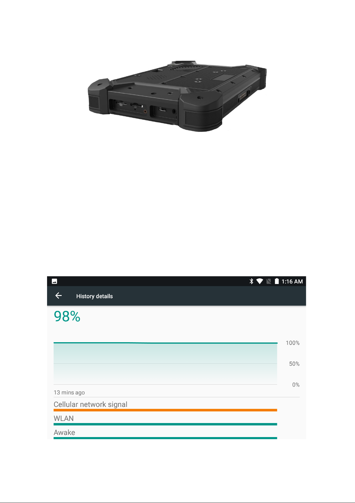
2.3.2 Checking the Battery Level
a. When the charging is in process, a battery indicator will appear in the status bar
showing the charging percentage. To view the charge percentage, swipe down the
Status Bar and you will see the charging percentage.

b. When the battery is fully charged, you can disconnect the DC input or USB
type-c cable. If available, please keep the device in charging by DC power supply.
See the details in “2.3 Charging the Battery”.
2.3.3 Installing/Replacing the Battery
In case you need to install or replace the battery, follow the steps below to access
the battery chamber and replace the battery.
1. Place the device on a flat surface, with the rear side facing up. Loosen the re-
taining screws on the back cover by using a Hexagon socket screwdriver with
flat head.
2. To install a new battery, orient the new battery so that the contact pins are
aligned correctly.
3. Assemble the battery cover and secure the retaining screws by using a Hexa-
gon socket screwdriver with flat head.
2.4 Optimizing Battery Life
If the VT-7 Pro is unable to keep charging by DC power supply, to optimize the op-
erating time of the battery, it is recommended that you do the following:
➢Decrease the LCD display brightness.
➢Set a shorter timeout of inactivity to allow the screen enter sleep mode.
➢Turn off the display if you are not using it.
➢Turn off Wi-Fi, Bluetooth or GPS function if you are not using it.
➢Turn off the App that heavily drains the battery if you are not using it. To view
the battery usage by individual App, swipe down the Status Bar in the upper
right corner and tap and hold the Battery icon.

➢Enable CPU power saving mode on battery settings page to limit the maxi-
mum CPU performance to conserve battery life and lower device tempera-
ture.
To access the battery settings page, swipe down the Status Bar in the up-
per right corner and then tap and hold the Battery icon.
Table of contents
Other 3Rtablet GPS manuals


