4ms Company Dual Looping Delay User manual

Looping Delay
4ms Company
User Manual 1.0 – May 22, 2023
The Looping Delay is a clock-based delay for creative synthesis. Not a tape or analog
emulation, but a modern crystal-clear digital delay, the Looping Delay combines features of
delay, looping, and sample-tight synchronization for powerful and dynamic sound capture and
modification. Based on the Dual Looping Delay, the Looping Delay offers the same high-
quality sound in a smaller, single-channel format.
• Stereo or mono mode (Return/Send becomes right channel In/Out in stereo mode)
• 87 seconds maximum delay/loop time in mono, or 43 seconds in stereo.
• 48kHz/24-bit sampling rate, loop recorded at 16-bit
• Extremely quiet, low noise, low jitter design
• Delay and loop time is sync-able to a clock, or a division or multiplication of a clock
• Infinite Hold mode for looping and windowing
• Reverse feature for toggling direction of playback
• Feedback ranges from 0% to 110%
• 1V/octave tracking for Resonant Delays (Karplus-Strong)
• Wet/Dry mix output, as well as dedicated Send/Return for feedback loop
• CV and trigger inputs for all features

Table of Contents
Setting up your Looping Delay
1. Power off your Eurorack system.
2. On the back of the Looping Delay you will see a 16-pin header labeled “-12V”. The 16-pin header
connects to a Eurorack power header using the included power cable. Connect one end of the
power cable to a Eurorack power header on your power supply distribution board and the other end
to the Looping Delay with the red stripe on the power cable oriented towards the bottom of the
module.
3. Using the included screws, securely attach the Looping Delay to the rails of your case.
4. Power on your Eurorack system.
Note: The Looping Delay is reverse-polarity protected, but incorrectly connecting any module in any
system can damage other modules on the power bus.
Setting up your Looping Delay! "..............................................................................2
Basic features:! ".......................................................................................................3
Controls and Jacks! "................................................................................................3
Infinite Hold vs. 100% Feedback! "...........................................................................7
Why do I hear something I played a long time ago?! ".............................................7
Signal Routing: Using Send and Return! "................................................................8
Advanced Usage 8
Loop start and stop points: Trimming the loop! "......................................................8
Windowing (aka Scrolling or Scrubbing)! "................................................................8
Using CV with Windowing! "...............................................................................9
Unquantized Time Mode and 1V/Oct CV! "..............................................................9
Stereo and Mono Modes! ".....................................................................................10
Octave Up/Down When changing Modes! ".....................................................10
Memory Clear! "......................................................................................................10
Quantized Change Mode! ".....................................................................................11
Using the Looping Delay with External Clocks! "....................................................11
Patch Ideas 12
Resonant Delay (Waveguide, Karplus-Strong)! ".....................................................12
Basic Resonant Delay! "....................................................................................12
Playing Resonance with a keyboard or sequencer! "........................................12
Sound on Sound Looping #1: Creating and Removing Layers! "...........................12
Peeling off Layers! "..........................................................................................13
Sound on Sound Looping #2: External Control! "...................................................13
Sound on Sound Looping #3: More External Control! "..........................................13
Granular Scrubbing! "..............................................................................................14
Special Features 15
Bus Clock Jumper! "...............................................................................................15
System Settings Mode! "........................................................................................15
Audio Bootloader! ".................................................................................................18
Firmware Version! ".................................................................................................18
Hardware Test Mode! "............................................................................................19
Factory Reset! ".......................................................................................................19
Technical Specifications!......................................................................................19
Page of2 20

Basic features:
• 87 seconds of delay/loop time in mono mode, 43 seconds in stereo mode
• 48kHz/24-bit sampling rate, loop is stored at 16-bit
• Extremely quiet, low-noise and low-jitter design
•Ping button and external clock jack set the timing for one "beat"
• Delay/loop time set as a number of musical beats (or fractions of beats) using the Time knob,
switch, and CV jack
• Sample-accurate master clock output for perfect synchronization
• Loop clock output
• Time switches change range of Time knob from 1/8th notes up to 32 bars
• Digital feedback, up to 110%
•Delay Feed control, independent of dry/wet signal mix
•Infinite Hold mode disables recording and plays a loop
• Start and End points of loop can be modified in real-time for “scrubbing” or “windowing”
•Reverse mode plays memory contents backwards
• Resonant Delays (ala Karplus-Strong)
• Delay time can be as short as 650uS
•Time CV jack can respond at 1V/octave in Unquantized Time Mode
• Trigger inputs for toggling Infinite Hold and Reverse
•Send and Return for feedback with external modules
•Send and Return function as right channel In and Out in stereo mode
• CV jacks to control Time, Feedback, Delay Feed (record level), and Mix
• Various algorithms can be selected interfacing with jittery external clocks (External Clock De-
jitter)
•Quantized Change Mode quantizes toggling of Infinite Hold and Reverse
•16HP Eurorack module
Controls and Jacks
Ping Button and Jack
The Ping button allows you to tap the tempo to set the base clock. One tap is
equal to one beat. The base clock can also be set by an external clock by
patching it into the Ping jack.
The Looping Delay requires a base time, which is referred to as a “beat” in this
manual. The delay/loop time is mathematically related to the length of one beat. If
you are familiar with other 4ms modules, you may be familiar with the concept of
“Ping”. In the Looping Delay, the beat is the Ping.
There are several ways to establish a beat:
•Tap the Ping button twice. One beat will equal the time between your taps.
• Patch an external clock into the Ping jack. One beat will equal the time
between the last two pulses received at the jack.
• Just turn on the Looping Delay and do nothing more! The Looping Delay
automatically boots up at 240BPM.
Another way of setting the timing is by jumping the Clock Bus header to RECV
and using a Clock Bus master (such as the 4ms QCD or MiniPEG) to send the
clock over the power distribution board. See the Bus Clock Jumper section on
page 16.
The Looping Delay’s clock is extremely stable and jitter-free. It's highly
recommended to use the internal Looping Delay clock (tap clock) if possible,
because it's quantized to the sample clock and has less jitter than most
commercially available clock sources. Using the Looping Delay as a master clock
will provide the tightest timing possible. However, if it's not possible to use the
Looping Delay as a master clock, you can sync to an external clock by patching it
Page of3 20

into the Ping jack. The Looping Delay will quantize the external clock to its own
sample rate and output quantized clocks on the Loop Clk Out jack. If there is any
jitter or drift in the external clock, the Looping Delay will track and follow these
discontinuities, which can result in interesting (or noisy!) artifacts. See section on
Using External Clocks section on page 12 for more information.
Inf. Hold Button and Hold Jack
The Looping Delay can operate as a delay/echo, or it can play a loop. Pressing
the Inf. Hold button toggles the state of Infinite Hold mode when the button is
released. Similarly, sending a trigger into the Hold jack toggles the state on the
trigger’s rising edge. The light on the button indicates whether the mode is on or
off.
Normally (Inf. Hold off), the channel records audio and plays it back after the
delay time has passed. Every sound the channel makes is continuously recorded
into memory. This works like a traditional echo or looping delay by recording and
playing continuously.
When Inf. Hold is on, the channel stops recording and only plays what's already
recorded in memory, cycling through a loop. The size of the loop is set by the
Time parameter. When you activate Infinite Hold mode, the Looping Delay will
start looping what you just recorded. The loop is defined by start and end points in
memory. Wherever the Looping Delay is reading from memory will become the
start of the loop, and where it was writing to memory will become the end of the
loop. You can get a sense of where the read and write positions are by listening to
the Wet and Dry signals, respectively—the Wet signal is what's being read from
memory, and the Dry signal is more or less what's being written to memory
(especially if Delay Feed is up and Feedback is down).
The diagram on the back of this manual (page 20) illustrates the difference in
signal flow when Inf. Hold is on vs. off.
Reverse Button and Jack
Reverse reverses the direction that memory is read and written.
Pressing the Reverse Button toggles Reverse on/off when the button is released.
When reversal is engaged, the Reverse Button will illuminate.
The Reverse CV jack toggles the reverse state on the rising edge of the trigger.
Reverse has slightly different effects depending on whether you are in Infinite
Hold mode or not. In normal mode (Inf. Hold off), toggling Reverse causes
playback and record to reverse direction. The read and write positions are also
swapped. This means that any audio that's already been recorded will be played
backwards, but any new audio will be played forwards (since it's recorded
backwards and played backwards, it comes out sounding forwards). Note that
when Time is very fast, Reverse will seem to have little effect because it only
reverses what's already recorded (which has a short duration when Time is fast).
Time Knob, Switch and CV Jack
The Time knob, switch, and CV jack perform simple arithmetic on the base time to
produce a delay/loop time. The red LED located between the knob and the switch
blinks in time with the current delay/loop time.
The Time knob sets the loop time in number of beats, ranging from 1 to 16.
The Time switch modifies the Time knob setting as follows:
•Center (=): the Time knob directly sets the number of beats for the loop or
delay time. For example, if the Time knob is pointing to 5, the channel will
make an echo (or loop) every 5 beats. Loop/delay time will range from 1 to
16 beats.
•Up (+16): 16 beats are added to whatever the Time knob shows. So if the
Page of4 20

knob is pointing to 5, the delay or loop time will be 5+16 = 21 beats. Loop/
delay time will range from 17 to 32 beats.
•Down (1/8): The Time knob is divided by 8, making the delay/loop time 8
times as fast (eighth notes). For example, if the knob is pointing at 5, then
the output will echo in 5/8th notes, or eight loops for every five beats. Loop /
delay time will range from 1/8 to 16/8 (2 beats)
The Time CV jack accepts signals from -5V to +5V. Using CV will modify the Time
knob's setting by multiplying or dividing the knob's value. Positive CV makes the
delay time longer, negative CV makes it shorter.
Taken together, the Time knob, switch and CV jack set the length of the loop or
amount of delay time. This period of time is relative to a beat (or base time), which
is set by tapping the Ping button or patching an external clock into the Ping jack.
For example, tap a tempo of 0.5 seconds. This makes one beat be 0.5 seconds
(120BPM).
Set the Time knob to 8, and center the Time switch. If there is no CV plugged in,
the delay time will be 8 beats, or 4 seconds.
Now flip the Time switch down to 1/8, the delay time will be eight 1/8th notes, or
0.5 seconds.
Now turn the Time knob down to 2, the delay time will be two 1/8th notes or 0.125
seconds.
Now flip the Time switch up to +16 and the delay time will be 18 beats, or 9
seconds.
Now apply some CV, the Time will get slower as you apply positive CV, and faster
as you apply negative CV.
Feedback Knob and CV Jack
The Feedback knob sets the amount of signal read from memory to be written
ahead in the future.
On the Looping Delay, Feedback ranges from 0 to 110%. With no feedback
(knob at 0), you will hear one echo. As you turn the Feedback knob up, you will
gradually hear more and more echoes (the amount of time before the echoes go
to silence will increase).
With Feedback at 100%, the signal read from memory is written back to memory
unaltered. Thus, the echoes will never fade out — an infinite loop. But if you input
a signal on the In or Return jacks, they will add to the feedback signal, which can
result in the sound gradually getting louder and louder as signal is added but
never reduced. The knob's range has been modified to create a large area which
is exactly 100%.
With Feedback at 110%, the signal read from memory is boosted before written.
This makes the echoes louder and louder each time. For short delay times, this is
a well-known “blooming echo” effect.
The Feedback CV jack accepts signals from 0V to +5V. Negative voltage on the
CV jack is ignored. The knob and CV jack are added together, and have a
maximum combined value of 110%. However, if the knob is set to 0%, then
applying a voltage of +5V or greater will cause a Feedback amount of exactly
100%. This allows you to easily access the 100% Feedback setting using CV.
Normally, Feedback has no effect in Infinite Hold mode. See the Windowing
section on page 9 for special usage of the Feedback knob and jack while holding
down the Inf. Hold button.
Page of5 20

Delay Feed Knob and CV Jack
Delay Feed is the amount of signal from the In jack that's recorded in memory.
You can think of it as “Record Level” or “Input Level”, but there is one important
detail to remember: Delay Feed doesn't effect the Dry signal (which is what's
present on the Audio Out jack when the Mix knob is turned all the way down). It
just effects how much signal is laid down or recorded. This detail is intentional
because when doing sound-on-sound techniques, you can play a sound
continuously in the Dry channel while modulating Delay Feed to fade in portions
of the signal onto the loop.
The Delay Feed CV jack accepts signals from 0V to +5V. Negative voltage on the
CV jack is ignored.
The knob and jack are added together and have a maximum combined value of
100%. Note that in Infinite Hold mode, Delay Feed has no effect since there is
no recording.
Mix Knob and CV Jack
Mix controls the blend between the Dry signal and the Wet signal on the Out jack.
It does not effect the Send jack. The Dry signal is taken directly from the In jack
(not the Return jack) before the Delay Feed parameter has any effect.
The Mix knob crossfades between signals on the In jack (dry) and signals read
from memory (wet). Turning the knob all the way to the left will yield a completely
dry signal. Turning the knob all the way to the right will yield a completely wet
signal.
The Mix CV jack accepts signals from 0V to +5V. Negative voltage is ignored. The
knob and jack are added together to produce the amount of dry/wet signal.
Input Jacks: In and Return
The In jack is the main audio input.
The Return jack has a different function in mono mode versus stereo mode (See
Stereo and Mono Modes, page 10). In mono mode, it’s the audio input from the
external feedback loop. Typically you will patch the Send jack (or a copy of the
main audio input) into an effect, and then patch the output of the effect into
Return. The signal on this jack will be mixed with the main audio input signal and
the internal feedback signal (controlled by the Feedback knob and jack) and then
recorded into memory. Note that the signal on Return jack will be written to
memory at 100% volume, without any attenuation. Therefore it’s recommended to
use an external attenuator to control the amount of external effect.
In stereo mode, the In jack is the left audio input, and the Return jack is the right
audio input. There is no effects loop capability in stereo mode.
Both jacks accept signals from -10V to +10V and are AC-coupled.
Output Jacks: Audio Out and Send
The Audio Out jack outputs the Dry/Wet mix.
The Send jack has a different function in mono mode versus stereo mode (See
Stereo and Mono Modes, page 10). In mono mode it outputs the delay signal only.
This is typically used with the Return jack to create an external effects loop. Note
that since the Return jack outputs the signal read from memory, the very first
echo will not be effected by the external effects loop.
In stereo mode, the Audio Out jack is the left audio input, and the Return jack is
the right audio input.
Page of6 20

Both jacks output signals from -10V to +10V and are DC-coupled.
Clock Out and Loop Clk Out Jacks
The Clock Out jack outputs the stable master clock. It sends a clock that’s in sync
with the base clock (“beat” clock or Ping clock), whether you tapped in a tempo or
are using an external clock.
The Loop Clk Out jack outputs a clock that’s in sync with the the loop/delay time.
All the clock outputs are quantized to the sample-rate. This insures they are jitter-
free (assuming your external clock has low jitter). The Looping Delay clocks are
some of the lowest jitter clocks available using Eurorack modules and should be
used whenever possible as a master clock.
The high voltage of the clock outputs is 8V. At fast clock speeds (audio rate), the
jacks output square waves.
In Inf. Hold mode, the clock goes high when the loop starts. This can be used to
trigger an envelope that VCA's the loop, for example.
Infinite Hold vs. 100% Feedback
Since setting Feedback to 100% (or close to 100%) and Delay Feed to 0% creates an infinite loop, the
Looping Delay acts similarly to how it does when Inf. Hold is on. However, there are a few important
differences:
When Inf. Hold is on, you can adjust the Time parameter from one setting to another, and then back to
the original setting and it will sound exactly the same as it did to begin with. This is not the case with
Inf. Hold off and Feedback at 100%; changing Time to a faster setting will actually record the new
shorter echoes into memory. Then when you turn back to the original slower Time setting, the Looping
Delay will be reading the shorter echoes and will repeat these in a longer echo. Therefore, even though
the Time setting is the same as it was originally, it will sound different.
Another difference is that when Inf. Hold is on, the Feedback knob has a special function: windowing.
Hold down Inf. Hold while turning Feedback to change the start and stop points of the loop (see
Windowing section on page 9). There is no windowing with Feedback at 100% and Delay Feed at 0%.
The final difference is that with Feedback at 100% and Delay Feed at 0%, there is the ability to fade in
new sounds (layers) by fading up the Delay Feed knob, or by applying CV (perhaps an envelope) to
the Delay Feed CV jack. Or you can create blank spaces by turning Feedback down momentarily. The
loop is more dynamic and mutable, versus when Inf. Hold is on, the loop is static and immutable.
Why do I hear something I played a long time ago?
Notes on the nature of Looping Delays...
When Inf. Hold is off, the wet signal (i.e. whatever's being output from the Send jack) is continuously
recorded into memory, going back for about one and a half minutes. This means that the results of
every knob you twist and every bit of CV you input is being recorded into memory. Let's say you're
playing a melody into the Looping Delay with a nice rhythmic echo. If, for example, you change the
Time parameter to make triplets for a moment, then switch back to eighth notes, then maybe bring
Feedback up to make a “bloom”, then pull down Delay Feed to cut the audio out, etc... all of this will
be recorded into memory.
Normally you won't have to think about this: the Looping Delay operates “as you think it should”,
overwriting whatever it recorded 87 seconds ago with what you're playing now. But in some special
circumstances, you can access this old memory: Windowing large chunks in Infinite Hold Mode is the
primary method whereby you might hear some sounds that were recorded onto the “tape loop” several
minutes ago. Another way often happens when Infinite Hold and Reverse are toggled many times
while Time is being modulated. This can be surprising! But it also can be very useful.
Page of7 20

Signal Routing: Using Send and Return
The Send and Return jacks are simple but offer a wealth of possibilities for creative patching. The
Send jack simply carries the delayed signal, unmixed with the input. It’s the same as the main Audio
Out jack if the Mix control is set fully clockwise. The Return input is summed with the main In.
However, it does not appear in the “dry” signal and is not attenuated by the Delay Feed knob and CV.
Feedback with External Processing
The classic use of Send and Return in a delay effect is to modify the delayed signal before it is
returned to the mix. Probably the most popular application of this kind of side-chain processing is a
simple low-pass filter in the feedback path. This causes succeeding repeats to soften, with less high-
frequency content on each pass. This is similar to the behavior of echoes in an acoustic environment,
and for this reason a low-pass filter is included in the internal feedback path of many conventional
delay processors. Note that the first echo will not be processed by the external effect, only the second
and subsequent echoes will go through the Send/Return path.
In patches involving externally processed feedback, the gain of the processing chain is always a
concern. In the case of filters in particular, the gain may be suitable overall, but not at the frequencies
you want to recirculate. If the filter is resonant, runaway feedback may occur even when the overall
gain is low.
Advanced Usage
Loop start and stop points: Trimming the loop
When Inf. Hold is on, changing Time will change the loop start point in
order to make the loop the new length. If you hold down the Reverse button
while changing Time, you will change the loop end point. Therefore, you can
change a loop that’s 4 beats long into one that's 5 beats long in two different
ways (adding a beat to the end, or to the beginning). There are many
creative possibilities to be explored with adding and subtracting from the
beginning and/or end of a loop. One idea is to “inchworm” up and down
memory. If you want to move more quickly than an “inchworm”, try windowing: see the Windowing
Section below.
Windowing (aka Scrolling or Scrubbing)
When Inf. Hold is on, the Feedback and Delay Feed parameters have no
meaning since they are effectively at 100% and 0%. However, the
Feedback knob and CV jack have a special purpose when Inf. Hold is on:
Windowing, also known as scrolling or scrubbing.
To use this feature, first makes sure you’re in Inf. Hold mode. Then, hold
down the Inf. Hold button while turning Feedback. This will cause the start
and stop points of the loop to scroll forward or backwards, depending on which way you turn the
Feedback knob. The amount of scroll is determined by how you turn Feedback: one full turn of the
knob equals one loop length. So if you have a 2 second loop, then turning Feedback from 0% to 100%
will shift the loop forward by two seconds. Turning Feedback from 100% to 50% will scroll the loop
backwards by one second.
Note: Windowing only works when Inf. Hold mode is on.
Windowing Tutorial
Let's try it. First get set up: Set Time so you have a loop length that's a few seconds long. Remember,
the red loop light will flash once per loop. To keep things simple for now, set Feedback low (25 - 50%
perhaps). Play some sounds for 10-20 seconds and then turn on Inf. Hold to lock them in.
Page of8 20
+
+

Listen to your loop, pay attention to what sounds the loop starts with, and what sounds it plays right
before it repeats. These are your loop start and stop points. Now, we're going to change those start and
stop points by Windowing:
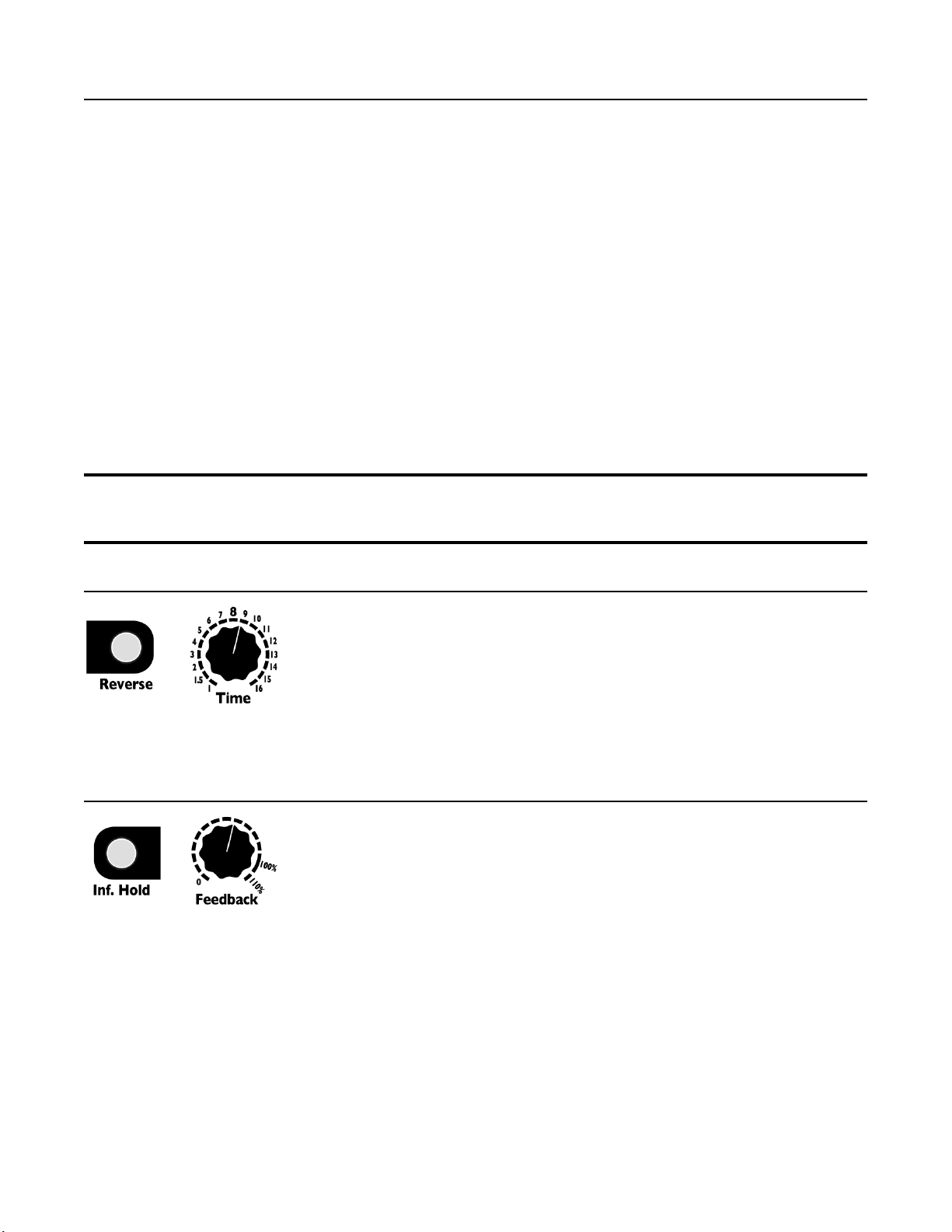
1. Turn Feedback knob all the way up (the sound will not change).
2. Hold down Inf. Hold while you turn Feedback to 0%.
You just shifted the loop backwards by one whole loop length. Let it play for a bit as you listen to the
new start and stop points. Hear it? The loop is the same length (same timing/tempo), but now it will be
playing the sounds you recorded a few seconds earlier. Play with this some more: Press and hold Inf.
Hold again and turn Feedback back half a turn. Hear how the loop now starts in the middle?
Remember that turning Feedback while in Inf. Hold mode has no effect unless you're holding down
Inf. Hold. This is critical for the next tip:
Tip #1: If you want to scroll more than one loop length, do this maneuver:
1. Turn Feedback to 100%.
2. Depress the Inf. Hold button while you turn Feedback to 0%.
3. Release Inf. Hold button.
4. Repeat as needed (turn Feedback to 100%, then press button and turn Feedback back to 0,
release button...)
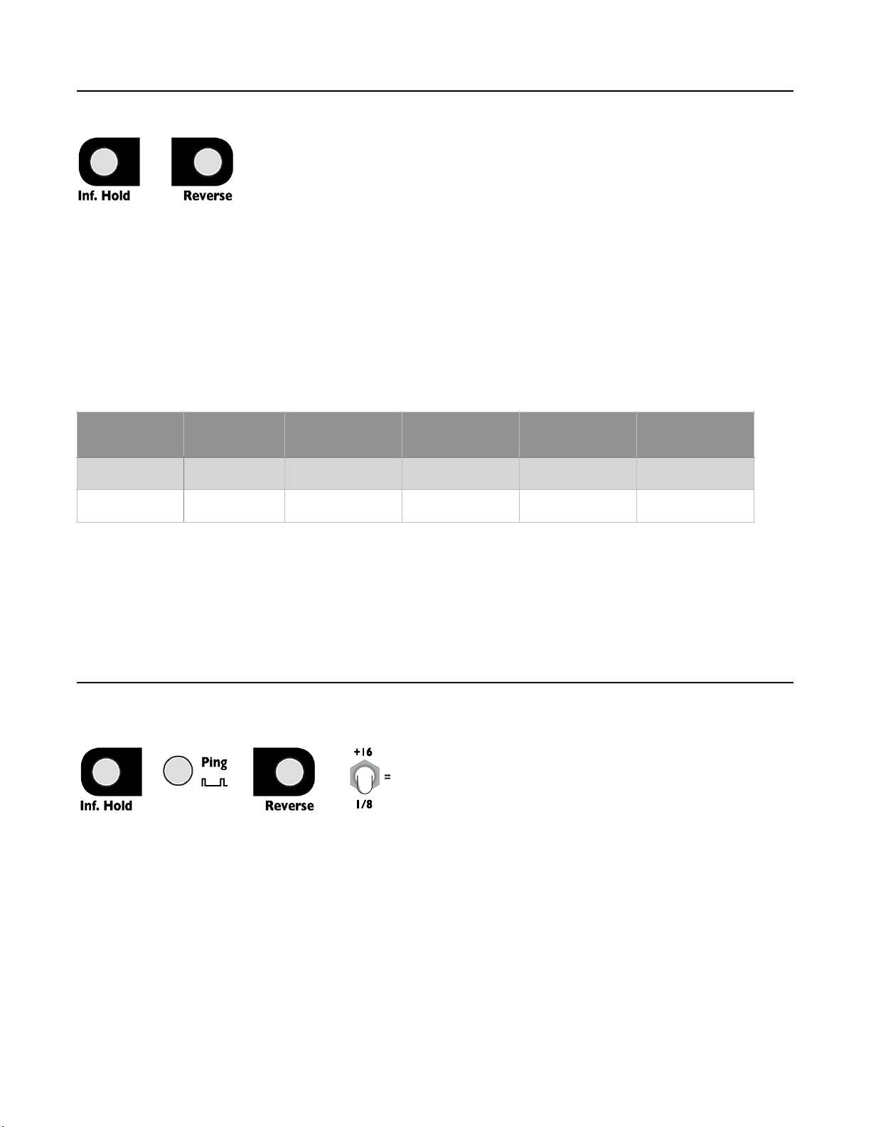
Tip #2: If you want to scroll back very far even more quickly than Tip #1, change the Time parameter to
very long (perhaps flip the time switch up to +16). Since turning Feedback + Inf. Hold scrolls by one
loop size, making the loop size enormous lets you scroll by enormous amounts with just one knob twist!
You can scroll back a maximum of 87 seconds in mono mode, or 43 seconds in stereo mode.
Tip #3: Set Time to a very short period and window around a loop with CV for a sort of granular effect.
Using CV With Windowing
The Feedback CV jack also allows you to window using external CV control. To enable the CV jack,
you must first manually hold down Inf. Hold and turn Feedback, even just a small amount. The
Feedback CV jack will now control the window.
If you turn the Feedback knob at any time without holding down Inf. Hold, the Feedback CV jack will
no longer control the window.
Unquantized Time Mode and 1V/Oct CV
Normally the Time knob and CV are quantized to integer amounts (1-16),
and simple fractions (1 – 1/16). This is called Quantized Time Mode, and is
the default mode. It's possible to change to Unquantized Time Mode, where
the knob and CV provide continuous control of the Time parameter (not
quantized to integers or simple fractions)
To change to Unquantized Time Mode, turn the Time knob while holding
down the Inf. Hold button. To change back to Quantized Mode, turn the
Time knob without holding down the Inf. Hold button.
In Unquantized mode, the Time knob behaves as usual, except it does not snap to the whole numbers
between 1 and 16. So you can sweep a slowly changing tempo, or set an exact tempo in between two
integer amounts. To adjust the Time knob in Unquantized mode, hold down the Inf. Hold button while
turning the Time knob.
The Time CV jack behaves differently in Unquantized mode: It responds over a 1V/octave curve for
positive CV (5 octave range). Applying up to +5V will multiply the Time knob's setting in an exponential
curve relative to the voltage. That is, for every additional volt on the CV jack, the Time period will halve.
This response is opposite to Quantized mode, where additional voltage makes the period increase. The
1V/octave response in Unquantized mode is very useful for resonant delays.
Note that if the Time switch is up, the 1V/oct response will be altered by the addition of the extra 16
beats. For a more accurate 1V/oct response, keep the Time switch centered or down.
Page of9 20
+

Stereo and Mono Modes
Normally, the Looping Delay operates in Mono Mode, where a mono signal is
input in the In jack, and the echoes, loops, and delayed signal is taken out of
the Audio Out jack. In this mode, the Send and Return jacks function as
additional inputs and outputs, but the delay signal path remains mono.
The Looping Delay can also function as a stereo delay by using the Return
and Send jacks as right channel input and output, and the In and Audio Out
jacks as left channel input and output. In Stereo Mode, there are two isolated
signal paths (left and right channels), whose parameters are always the same. That is, the Time,
Feedback, Delay Feed, and Mix amounts are always the same for both channels, being controlled by
the knobs and CV jacks. In Stereo Mode, the maximum delay time is exactly half of the amount in Mono
Mode.
To change between Mono and Stereo Modes, hold down the Reverse and Inf. Hold buttons for about 2
seconds. The Reverse and Inf. Hold lights will flash to indicate which mode is now active: rapidly
alternating means Stereo Mode, and more slowly flashing together means Mono Mode. Release the
buttons when you see the lights flash. There may be a discontinuity, click, or some unwanted sounds
when changing modes.
Octave Up/Down When Changing Modes
If you have any sound already recorded into memory (for example, if you’re looping, or if you have
Feedback set above zero and played something recently), the pitch of that sound will jump up or down
by an octave. When changing to Stereo Mode, the pitch will jump up, and when changing to Mono
Mode it will jump down. This can be used as a special effect, but if you don’t want to hear this effect,
clear the memory before changing modes (see next section).
Memory Clear
When using the Looping Delay with Feedback up
and long loop times, it can take a while for the
sound to die out after the input signal is muted.
This is, of course, a very nice and useful effect, but
if you find yourself needing to clear the memory
more quickly you can do so by making sure the
Time switch is down or centered, and holding down
all three buttons (Reverse, Ping, and Inf. Hold) for
about three seconds. The lights will flash once and you may hear a beeping sound briefly while the
memory is cleared. Let go of the buttons and the buffer will be cleared. Note that if the Time switch is
flipped up, this button combination will enter System Mode. If you accidentally do this, press and
release all three buttons quickly to return to Normal Mode.
Page of10 20
Hold 2 sec.
+
Hold all buttons 2 seconds…
+
+
with Time down
or center
Max Echo/
Loop Time
In jack
Audio Out jack
Return jack
Send jack
Mono Mode
87.4 seconds
Mono input
Mono output
FX Return
FX Send
Stereo Mode
43.7 seconds
Left input
Left output
Right input
Right output

Quantized Change Mode
Normally Reverse, Inf. Hold, and Time work as you would expect: changes to
the control take effect immediately, no matter when they occur. In the
Quantized Change Mode (or QCM), any change to these parameters will be
delayed until the next pulse of the Ping clock.
This means that if you press the Reverse and Inf. Hold buttons, turn the Time
knob, flip the Time switch, or apply CV or gates to the Time, Reverse and Hold
jacks, no change will be made until the next Ping clock. If the Ping clock changes (due to tapping the
Ping button or a change in the tempo of an external clock patched into the Ping jack), then any queued
changes to parameters will immediately take effect.
The factory default setting for QCM is off. To enter QCM, hold down the Reverse button and tap the
Ping button once. The Ping and Reverse lights will flash three times evenly to show entry into QCM.
Exit QCM with the same procedure, in which case the same lights will flash six times in a staggered
pattern.
QCM is best explored with a rhythmic patch, sequencer, or drum unit locked with the Looping Delay
clock. Asynchronous modulations and triggers can be used freely, since they will be forced to quantize
with the Ping clock. In this sense, QCM might be thought of as a kind Sample and Hold that locks
modulation sources with the fundamental time. Go ahead, experiment! It can be addicting.
Note that continually toggling Reverse in this mode can lead to quite a lot of “memory scraps” that
come back at surprising times, especially when the Reverse switching continues after an input source
is killed. This can be a real plus as these bits and pieces will remain locked to the clock. If it gets out of
hand, you can use the Memory Clear function, or discontinue triggers to Reverse so that the “scraps”
eventually clear themselves out.
Using the Looping Delay with External Clocks
Whenever possible, use the Looping Delay as a the clock source by patching out of the Clock Out
jack to your other clock modules. However, sometimes you have to clock the Looping Delay with
another source, in which case you would patch the external clock into the Ping jack. There are many
issues with clock sync that arise from using different manufacturers’ gear together, and an investigation
of every type of issue is beyond the scope of this section. However, here are some initial things to try if
you are having difficulties syncing clocks:
•Use the least jittery device as the clock source. Try to use the Looping Delay, or some other
high-end gear that guarantees a low-jitter clock. Analog devices generally drift over time. Digital
devices can also have jitter due to rounding errors and processor lag or latency. If you're using
something else as the clock source, try running it directly into the Looping Delay and then using the
Looping Delay’s Clock Out jack as the clock source for other gear.
•Try running the clock source into a clock divider before into the Looping Delay. This will
average out some jitter, and slow down how often the Looping Delay’s ping time is updated. You
may wish to configure your clock source equipment to generate a faster clock (such as 24ppq or
48ppq) and then divide it down with a Rotating Clock Divider or some other clock divider module.
•Try the Looping Delay’s five different External Clock De-Jitter modes (see System Settings
Mode section). One mode in particular may work best with your equipment. Analog clock sources
tend to drift, so Linear Average of 4 is best (or use a clock divider, see above). Digital clock sources
with Inf. Hold on the Looping Delay might prefer a Moving Average of 2, or Ignore 1%. Digital clock
sources without Inf. Hold on the Looping Delay might prefer Ignore 1% or Ignore 0.2ms if you are
concerned with phasing between the layers.
Page of11 20
Hold… and tap

Patch Ideas
Resonant Delay (Waveguide, Karplus-Strong)
Basic Resonant Delay
Resonant Delays are delays with short delay time (in the audio range) and enough feedback to create a
resonant sound somewhat like that of a plucked string.
The Looping Delay supports resonant delays. Simply tap a very fast tempo and flip the Time switch to
1/8. Alternatively, feed a square wave LFO into the Ping jack. The LFO should be in the low or mid
audio range, around 20-50Hz is the most stable, but up to 500Hz will work.
Next, feed a signal into the In jack: a noise burst or a short sample from the STS or Sampler (Length
set near minimum) is an excellent sound source. You also can use a trigger (keep in mind the amplitude
of the trigger will effect the sound).
Use the Time switch and knob to set the pitch. Feedback sets the resonance, and Delay Feed effects
the level and resonance as well. Make sure Inf. Hold is off. The frequencies present in the input signal
can ring loudly at particular settings, so be prepared for surprises!
If you consistently have unstable results when using an external clock into the Ping jack, try setting the
External Clock De-jitter setting to a different value. Small amounts of jitter in the external clock can
cause large changes in the sound.
Playing Resonance With a Keyboard or Sequencer
Holding down Inf. Hold and turning the Time knob changes the Looping Delay into Unquantized Time
Mode (see section on page 10 for discussion). This feature is great in combination with Resonant
Delays. First, get a nice resonant delay sound happening. Then hold down the Inf. Hold button and
turn the Time knob slowly. You should hear the pitch of the resonance change smoothly (not stepping
through quantized pitches). Now, plug a 1V/octave keyboard or sequencer output into the Time CV
jack. Plug the velocity output (or an envelope output that's triggered by each step of the sequencer) into
the Feedback jack. Turn down the Feedback knob so that the velocity/pressure or the envelope make
the Looping Delay create individual “notes”. You can also patch into Delay Feed to get a different
effect.
Sound on Sound Looping #1: Creating and Removing Layers
With the Looping Delay you can build a loop by layering audio on top of itself. Since the Looping
Delay is always recording when not in Inf. Hold mode, each time you add a layer, the audio will be
recorded. You can then use the Windowing feature to scrub backwards in time, essentially peeling off
newer layers, or scrub forwards to restore the layers.
Tap a tempo on the Ping jack of about one second. Turn the Time knob to 8, and flip the Time switch
to = (center). This creates a loop of about eight seconds (or eight “bars", if you consider the Ping clock
to be one bar). Make sure Inf. Hold is off.
Start with Feedback at 90-100%, Delay Feed at 100%, and Mix at center.
Play a sound into the In jack. It can be a short burst, a drone, random noises, anything. Since you’ll be
layering more things on top, try to keep it under 8 seconds when you do this the first time. After you
finish, press Inf. Hold to lock the loop in. If you want all your layers to be 8 bars each, then only turn
Inf. Hold on or off when you see the red light go from off to on.
Tip: Enabling Quantized Change Mode will force enabling/disabling Inf. Hold to happen exactly on the
Ping clock (which happens every second). You also could wait until the red light goes off, patch Loop
Clk Out into the Hold jack, and then unpatch it after the red light goes on.
You should now be hearing the sound repeating every eight seconds.
Page of12 20

Next, prepare to play a different sound. If this is your first time doing this patch, try to make this sound
distinct from the first so you’ll recognize it easily. When you’re ready to play the second sound, turn off
Inf. Hold and play the sound. When you’re done, turn Inf. Hold back on, either by pressing the button
or using any of the techniques mentioned above.
Repeat this process to add more and more layers: turn Inf. Hold off, play the sound, turn Inf. Hold on.
You can control the level of each layer by adjusting the Delay Feed knob. Turning it down will make the
new layer more quiet. If your sound is a constant tone or drone, consider turning Delay Feed to 0
before turning Inf. Hold off. Then fade Delay Feed up. When you’re done, turn Delay Feed back down
to 0. This will make the new layer fade in and out.
You also can control the level of the previous layers by adjusting Feedback. Turning Feedback down
will make older layers fade out each time they’re played.
Peeling off Layers
After you’ve built up several layers, you can experiment with “peeling” them off. Make sure Inf. Hold is
on. Turn Feedback all the way up (110%). Press and hold Inf. Hold and turn Feedback down to 0.
Release Inf. Hold. You should hear the last 8 seconds of audio removed from the loop. If you recorded
exactly 8 seconds each time, then the last layer will be gone. What happens is that Inf. Hold +
Feedback adjusts the loop start and end times. By turning Feedback counter-clockwise while holding
Inf. Hold, an earlier portion of memory is played, before you recorded the latest layer.
To peel off another layer, turn Feedback back to 110%, then hold Inf. Hold while you turn it back to 0%.
If you want to restore the layer, do the opposite motion: turn Feedback to 0%, hold Inf. Hold while you
turn it to 110%.
You also can pull out parts of a loop by turning Feedback less than a full turn. For example, if you turn
Feedback from fully up to center, only the previous four seconds will be removed.
Another technique is to turn the Time knob. The amount Inf. Hold + Feedback shifts the loop is relative
to the Time parameter. If you turn the Time knob down to 1, then a full turn of Feedback will only shift
the loop by 1 bar.
Sound on Sound Looping #2: External Control
This is a great patch for long loops. Set a long gentle clock speed. Turn the Time knob to 16 (or
something slow). Turn Feedback to 100%, Delay Feed to 0%, and turn Mix to 50% (or to taste). Now
run audio into the In jack. Try running a melody, a percussive sequence or an evolving drone,
perhaps.
Patch a manual CV source into the Delay Feed CV jack. It can be anything that generates CV when
you activate it: a keyboard with velocity or pressure output, a manual CV knob (from the 4ms SISM),
or perhaps an envelope output that's triggered manually (by quickly tapping the Cycle button twice on
the 4ms MiniPEG or EnvVCA). When you apply CV, you will bring up the Delay Feed parameter
which causes audio to be recorded onto the loop.
Since Feedback is at 100%, the loop is infinite and everything you lay down will remain (but take care
to keep your levels not too hot or else you will eventually get clipping). A variation is to use the Send
jack for the loop output. Then set the Mix knob to center and use the Audio Out jack to monitor the
incoming audio.
Sound on Sound Looping #3: More External Control
In this variation, you can use one CV signal to bring in sound, and another to clear the loop or fade it
down. This requires a module that can invert and offset a CV signal, such as the 4ms SISM, the
Makenoise MATHS, or any number of CV utility modules.
Patch the previous patch, then turn Feedback down to 0%. Patch a second manual CV source into the
4ms SISM (or other utility module). Turn the SISM's Scale knob all the way down to – (invert), and turn
Page of13 20

the SISM's Shift knob up to about 2:00. Patch the SISM channel's output to the Looping Delay’s
Feedback CV jack.
Now you can activate the “record” CV like in the previous patch to lay down new material, but you can
also activate the “clear” CV to fade out material from the loop. You can even activate both pads at the
same time to replace loop material with new material.
What's happening in this patch is that the SISM is turning the 0V to 5V signal (or 8V or whatever the
maximum) from the pad module into a 5V to 0V signal. So, the SISM will output around 5V if you are
not pressing on the manual pressure pad (no CV signal). This means the Looping Delay’s Feedback
will be 100%. As you press on the pad and increase the voltage from the pad module, the SISM will
decrease its output voltage, which decreases the Feedback parameter. When Feedback is low,
material from the loop fades away.
Note that if your loop is not looping at 100%, then the SISM's Shift knob needs to be turned up a bit.
This insures at least 5V is coming out of the SISM when nothing is being input.
Granular Scrubbing
A really neat effect can be obtained by changing the Reverse jack to respond to gates, and patching a
PWM pulse wave into it. This allows you to scrub across “grains” in an audio loop at variable playback
speed without changing the pitch.
First, enter System Setting Mode and set the Reverse jack to Gate Mode (See System Settings Mode,
page 16). Then patch audio into the In jack and take the output from the Audio Out jack. Tap a slow
tempo, maybe one second, and set Time so the loop time is a couple seconds. Turn Feedback down
and Delay Feed up. Play some audio, perhaps a drum loop, a vocal sample, or a melody line. Let the
audio play through (make sure Mix is set at least 50/50), and then press Inf. Hold to lock in the loop.
Listen to the loop play once or twice to get a feel for what it sounds like normally.
Now the trick! Patch a pulse wave with variable pulse width (sometimes called PWM) from your favorite
LFO or clock module to the Reverse jack. The 4ms QCD with the QCD Expander work nicely by using
the Gate PW knob to adjust pulse width. You can also use the EOR or EOF output from the any of the
4ms EnvVCA modules and use the ratio of Rise and Fall sliders to set the pulse width. The frequency
should be between about 2Hz and about 20Hz.
At first, set the pulse width to about 60-70% or so. You should see the Reverse light flicker, and the
loop should immediately start playing slowly forward or backwards. Tap the Reverse button to make it
play the other direction. Change the LFO’s pulse width to adjust the playback rate. As you approach
50%, the loop will slow down, until it hovers at 50% and then starts playing back in the opposite
direction.
The frequency of the VCO changes the “grain” size. At 2Hz there is a noticeable “stutter”, and at 20Hz it
sounds like a medium/low fidelity granular effect. If the VCO is too fast or if the pulse width is too
extreme, the effect will be lost.
The reason this effect works is because it plays forward when the pulse is low and backwards when the
pulse is high (or vice-versa if you toggled Reverse with the button). So, a pulse width of 50% will
effectively hover on a single grain because it plays forward and backwards equally. But, a pulse width
of 60% will play forward for 60% of the time and backwards 40% of the time, thus slowly moving
forward at 20% speed. The makes the audio slow down to 1/5 speed without any pitch shifting.
Page of14 20

Special Features
Bus Clock Jumper
Bus Clock is a 1:1 clock that runs along the Gate pin of the power system.
Modules such as the 4ms QCD, RCD, SCM+, PEG, DLD, SWN, and MiniPEG
are compatible with the clock bus system. To use the Looping Delay on a bus
clock system, install the jumper in one of two positions:
Bus Clock Send:
Connect the jumper on the lower position (“SEND”) to send the master clock
from the Looping Delay to the clock bus. The clock will be identical (but
separately buffered) as the signal on the Clock Out jack. It is not recommended
to have more than one device sending on the same clock bus system.
Bus Clock Receive:
Connect the jumper on the upper position (“RECV”) to receive a ping clock from the clock bus. The
signal on the bus clock will be automatically patched to the Ping jack. By plugging a cable into the Ping
jack, the bus clock will be disconnected from the Looping Delay.
Note: When receiving a bus clock, you must stop the external bus clock or patch a dummy cable into
the Ping jack in order to use the Ping tap button.
Bus Clock Disabled:
Remove the jumper completely to disable clock bus support. This is the factory-default. It’s safe to
connect the jumper to only one pin.
System Settings Mode
System Settings Mode allows you to change the way some features of the Looping Delay behave. For
novice users, these are not necessary to modify, but advanced users may wish to explore.
It's recommended that new users get familiar with the Looping Delay operation using default system
settings before making changes!
In order to enter or exit System Settings Mode, the Time switch must be flipped up.
To enter, flip the Time switch up and hold down all three buttons for two seconds. Release the buttons
when you see all the buttons’ lights turn off.
There are two ways to exit System Settings Mode:
1) Exiting while temporarily saving changes is similar to the process of entering System Settings
Mode. Flip the Time switch up and briefly press all three buttons. Make sure to release the buttons
within 2 seconds or less. The changes you made will stay in effect until you power the module down.
The next time you power it up, the previous settings will be restored.
2) To exit while permanently saving changes, turn the Time switch up and hold down all three buttons
for 2 seconds. The Reverse and Inf. Hold button lights will flash rapidly to confirm saving. Settings will
be saved even after powering down.
Page of15 20

Note: In order to keep your tap tempo Ping time when you enter System Settings Mode, depress either
of the other two buttons before pressing the Ping button. If you press the Ping button before the other
buttons, the Looping Delay will register that as a tap and the tempo will change.
Proceed carefully and take the time to understand what you are doing before pressing any
buttons, turning any knobs, or flipping any switches. Changing a System Settings without realizing
what you changed can cause confusion. You can always do a Factory Reset if you want to revert to
safe settings (see Factory Reset section below).
The Time switch is used to determine what parameters you are editing. The buttons and knobs edit
parameters.
Time Center: Auto Mute, Soft Clipping, and Crossfade Time
Auto Mute:
Tap Inf. Hold to toggle Auto Mute on and off. When the light is on, Auto Mute is enabled.
Auto Mute is a noise gate that silences the input when a signal is very low. This prevents runaway
feedback if Feedback is turned up and the module is allowed to run for a long time with no input
signal. Turning it off will introduce extra noise, including small amounts of clicking when the gate
output jacks fire. It’s highly recommended to leave Auto Mute on.
Soft Clipping:
Tap Ping to toggle Soft Clipping on and off. When the light is on, Soft Clipping is enabled.
Soft Clipping enables compression when the output signal exceeds 75% of the clipping point. Below
this point, the signal is unaffected. This saturation distortion is often more pleasing than harsh clipping.
Crossfade Time:
Hold down Reverse while turning Time to 1, 4, 6, 8, 10, 12, or 16 to set the Crossfade Time (CFT).
Time at 1: CFT will be 0ms (cross-fading disabled). Reverse will periodically flash once.
Time at 4: CFT will be 2ms. Reverse will periodically flash twice.
Time at 6: CFT will be 4ms. Reverse will periodically flash three times.
Time at 8: CFT will be 8ms. Reverse will periodically flash four times.
Time at 10: CFT will be 25ms. Reverse will periodically flash five times.
Time at 12: CFT will be 100ms. Reverse will periodically flash six times.
Time at 16: CFT will be 250ms. Reverse will periodically flash seven times.
Any time the Looping Delay’s read and write “heads” jump from one address to another, there is a
short cross fade created in order to smooth out the splice. This occurs whenever the Time setting is
changed and whenever Reverse or Inf. Hold is toggled. Also, in Inf. Hold mode, when the audio
reaches the end of the loop it cross-fades back to the start. In most cases, the default timing (8ms) of
the cross fade is sufficient and will make the module operate seamlessly. However, advanced users
may wish to experiment with other settings.
Disabling Crossfade Time allows for instant movement between points, at the expense of creating
clicks and pops. This can be improved by enabling Quantized Change Mode (see section page 11)
because QCM forces the clicks to only occur on the beat. On the other hand, using a longer Crossfade
Time makes all transitions very smooth and natural sounding, while limiting how quickly the
parameters can change. In any setting of CFT and when Inf. Hold is on, if the loop size is shorter than
the Crossfade Time, then cross-fading will be disabled in order to preserve the loop size.
Page of16 20

Time Down: Reverse/Hold Gate/Trigger and External Clock De-jitter
Reverse/Hold jacks Gate/Trigger input:
Gate/Trigger input for Reverse jack: Tap Reverse to toggle mode (lit=gate, unlit=trigger)
Gate/Trigger input for Hold jack: Tap Inf. Hold to toggle mode (lit=gate, unlit=trigger)
The input jacks for Reverse and Inf. Hold can be set to toggle the state when they receive gates or
triggers. In Trigger Mode, it will toggle every time a trigger is received. For example, the first time the
Reverse jack receives a pulse, Reverse will turn on. The next time it receives a pulse, Reverse will
turn off.
In Gate mode, the feature will toggle states every time the jack toggles states. For example, if you send
a gate into the Reverse jack, Reverse will turn on when the gate goes high and stay on until the gate
goes low (at which point Reverse will turn off). Pressing one of the buttons in either mode will always
toggle the state. Additionally, in Gate Mode, pressing the button will toggle between whether a high gate
= On or a low gate = On. This effectively inverts the gate signal.
Default is Trigger Mode.
External Clock De-jittering:
Hold down Ping while turning Time to 1, 4, 8, 12, or 16 to set the ECD algorithm:
Time at 1: Ignore clock pulses that deviate by 0.2ms or less. Ping will periodically flash once.
Time at 5: Ignore 1% deviation or less. Ping will periodically flash twice.
Time at 8: Accept all clock pulses (ECD Disabled). Ping will periodically flash three times.
Time at 11: Moving average of the past 2 clock periods. Ping will periodically flash four times.
Time at 16: Linear average of the past 4 clocks. Ping time only updates every 4 clocks. Ping will
periodically flash five times.
The Looping Delay has a very precise and jitter-free internal clock (less than 0.0001% at 120BPM). If
ever possible, it's recommended to use the Looping Delay as the master clock. However, using
external gear to clock the Looping Delay is also possible. One problem with using external clocks is
that lots of equipment generates clocks with a lot of jitter. Sometimes the tempo may vary by as much
as 2-3BPM. Since the Looping Delay is always recording things to be played back in the future, if the
tempo changes from when the audio was recorded to when it plays back, it will sound out of time. In
order to compensate for this, the Looping Delay has five algorithms that each work with different
types of external clock jitter.
If you need to use an external clock that has jitter, it's recommended you patch a simple patch and try
each of the five algorithms to see which one suits the particular type of jitter and your patch. Note that
in the case of the two Averaging ECD settings, adjusting the external clock speed will cause the
Looping Delay to slowly “catch-up” before “locking-on”.
The default setting is Ignore 1% deviation. With drifting analog clock sources, Linear Average of 4 is
recommended.
Page of17 20

Audio Bootloader
The Looping Delay contains a bootloader that is used to update the firmware by playing an audio file
into the In jack on the left side of the module. Firmware audio files can be downloaded from the 4ms
website at https://4mscompany.com/ld
1. To enter bootloader mode, power off the Looping Delay and connect a computer or smart
phone audio output to the In jack. Either a stereo or mono cable is fine. Connect the Send jack
to an amp/speakers so you can listen.
2. Set the computer/phone's volume to 50%. You may need to adjust it up or down if this is too
loud or quiet (see step 5). Unlike other 4ms modules, the Looping Delay’s bootloader is
designed to work with consumer line-level signal (a peak-to-peak voltage of a little under 1V is
ideal, or -10dbV). Turn off all audio notifications that might interrupt playback.
3. Depress the Reverse and Inf. Hold buttons while powering on the Looping Delay. When you
see either button blink, release the buttons.
4. If Reverse is blinking, press the Reverse button. Inf. Hold will start blinking to indicate the
module is now ready to receive firmware.
5. Begin playing the file. Immediately you should see the Inf. Hold and Ping lights flash. Do not
interrupt this process!
6. The Inf. Hold light blinks in a way that tells you if the audio is too loud or quiet. If it blinks
erratically, then the audio is too loud or too quiet. If it blinks regularly with equal times on and
off, then the audio level is ideal. A good way to set the level is to start with the volume all the
way down and notice the the light is off. Then slowly bring it up until it flashes regularly (about
four times per second with equal times on and off).
7. If there’s an error, the Reverse light will start blinking about three times per second, and the
Ping light will be off. The Inf. Hold light will continue to indicate the audio level, so this is a
good time to verify the level is ideal and adjust the output level as needed. Verify the cable is
not loose, all sounds/vibrate/notifications are off, and that you have downloaded the audio file
completely (avoid streaming or playing from the browser). Stop the audio file, reset it back to
the start, and tap the Reverse button to reset. The Inf. Hold button should blink slowly. Play
the file from the beginning again.
8. If the file loads successfully, the Reverse button will blink once every two seconds and the
Ping button will blink every second. Press Inf. Hold to start playing.
The open-source licensed source files (in C++, for compiling with arm-none-eabi-g++) can be found at
https://www.github.com/4ms/looping-delay
Firmware Version
To view the firmware version, hold down Reverse and Ping while powering up. After you release the
buttons, the red light will flash to indicate the firmware version. Power off.
Firmware v1.0 (released June 2023)
Flash once
Page of18 20

Hardware Test Mode
The Hardware Test Mode is a way to verify your hardware is working correctly. This procedure is run
on every unit at the factory. If you built the Looping Delay as a DIY Kit, or if you suspect damage
occurred to your unit, you can run this procedure to verify the module is working properly.
The full procedure is described in the DIY Looping Delay Kit Build Guide found at
https://4mscompany.com/
Factory Reset
A factory reset is not necessary unless you have changed System Settings or recently upgraded
firmware versions.
To perform a factory reset, hold down Reverse and Ping while powering up. After you release the
buttons, the red light will flash to indicate the firmware version. The Ping light will then flash
repeatedly. Hold down the Ping button for five seconds until it turns on solid. Release Ping.
The Looping Delay has now been reset to its factory default settings. Power off.
Technical Specifications
• 16 HP Eurorack format module
• 0.98” (25mm) maximum depth with power cable
Power consumption:
• +12V rail: 125mA max
• -12V rail: 45mA max
• +5V rail: not used
Audio Inputs
•20Hz to 20kHz
• 20V peak-to-peak maximum before clipping (when AC coupled)
Audio Outputs
• 0Hz (DC) to 20kHz
• +10V to -10V maximum output
Clock Out:
• 0V to 8V
• +/- 2.4µs maximum jitter (0.001% at 120 BPM)
• Rise/Fall time (10% to 90%): 350µs
Loop Clk Out:
• 0V to 8V
• Rise/Fall time (10% to 90%): 350µs
Sampling
• 24-bit sampling at 48kHz, 32-bit floating-point processing, 16-bit storage in RAM
• 64Mbit SDRAM chip
• Mono mode: Maximum of 87.38 seconds
• Stereo mode: Maximum of 43.69 seconds
Page of19 20

Page of20 20
+
External
feedback
loop
(eects, etc.)
READ
WRITE
87 second “tape loop”
moving at constant speed
Reverses direction of “tape”,
and swaps position of read
and write “heads”
Moves write “head”
Loop only
(no dry signal)
READ
Variable size“tape loop”
moving at constant speed
Reverses direction of “tape”
“Time” makes loop longer
or shorter by changing
start point of loop
(Hold down Reverse
while turning Time
to change end point) Holding down Inf. Hold while
turning Feedback knob
changes start and end
point of loop simultaneously
(”Windowing” or “Scrubbing”)
OFF
ON
+
Inf. Hold/Loop Mode:
Delay Mode:
Inf. Hold
Inf. Hold
Inf. Hold
Time
Time
Feedback
Feedback
Mix
Mix
Other manuals for Dual Looping Delay
1
Table of contents