A/DA Delta-88 User manual

1
Contents
SAFETY INSTRUCTIONS .............................................................................................................................................................................2
Description of the DELTA System..............................................................................................................................................................4
Delta-88 Connections ................................................................................................................................................................................17
Delta-88 Main AC Connections .................................................................................................................................................................22
Using ACC-48s for both source and amplifier AC switching. ...............................................................................................................25
Delta-88 Other Main AC Connections ......................................................................................................................................................27
Source AC Control Connections ..............................................................................................................................................................28
Home Theater Options ..............................................................................................................................................................................38
Home Theater - Option 1 ...........................................................................................................................................................................39
Home Theater - Option 2 ...........................................................................................................................................................................40
Home Theater - Option 3 ...........................................................................................................................................................................41
Home Theater - Option 4 ...........................................................................................................................................................................42
Home Theater - Option 5 ...........................................................................................................................................................................43
VS-3 As Scrolling Input Selector ..............................................................................................................................................................44
System Bus Wiring - Multiple Delta-88s ..................................................................................................................................................56
ADA Bus™ Wiring - Networks ..................................................................................................................................................................58
ADA Bus™ Wiring - Networks (cont.) ......................................................................................................................................................60
Installation of ADA Keypads .....................................................................................................................................................................66
Rack Rail & Hardware and ........................................................................................................................................................................67
Rack Mounting Source Components. ......................................................................................................................................................67
Delta System Wiring ..................................................................................................................................................................................68
ADA Bus™ Wires .......................................................................................................................................................................................68
Home Run Wires ........................................................................................................................................................................................69
Rear Access ...............................................................................................................................................................................................69
No Rear Access ..........................................................................................................................................................................................69
Step A - Installing the Rack.......................................................................................................................................................................70
Step B - System Mainframe AC Wiring ....................................................................................................................................................70
Step C - Sources - Sources to Delta-88, ACC-3000 (or ACC-48), & PCT-8 ...........................................................................................70
Step D - Composite Video Wires (if needed) ...........................................................................................................................................71
Step E - Outboard Amplifier and Subwoofer Connections ....................................................................................................................71
Step F - Speaker Wires ..............................................................................................................................................................................71
Step G - Low Voltage Wires ......................................................................................................................................................................71
Step H - Connection of the Delta-88 Linking Cable ................................................................................................................................71
Step I - ADA Bus™ Connections ..............................................................................................................................................................71
Step J - AC Connections ...........................................................................................................................................................................72
Step K - Connection of ADA Components to the WH-3000 ...................................................................................................................72
Critical Wiring Tips ....................................................................................................................................................................................72
Step L - Verifying Proper AC Control of All ADA Bus™ Components..................................................................................................73
Step M - Initial Delta-88 Setup & Labeling of Room & Source Names ..................................................................................................74
Step N - Connection of the Delta-88s to the WH-3000 ............................................................................................................................76
Step O - Checking the First Keypad and Zone ........................................................................................................................................76
Step P - Testing all Zones from the First MC-3000 or MC-3800 .............................................................................................................79
Step Q - Connection of the MT-3000 Multi-Tuner....................................................................................................................................80
Step P - Connection and Testing of the PCT-8 or PCT-4 Source Controller ........................................................................................85
Step Q - SSD-66 (THX) Home Theater Systems ......................................................................................................................................90
Step R - Testing More Rooms ...................................................................................................................................................................94
Step S - Programming the Delta-88 for Special Cards or No Cards......................................................................................................96
Step T - Custom Source Programming - VS-3s and Special CD/LASER Controllers ..........................................................................98
Step U - Custom Keypad Source Programming - Local VS-3 Outputs or Local Only Sources ........................................................100
Delta-88 IR Remote Configuration..........................................................................................................................................................103
Delta-88 Room Activation Option ...........................................................................................................................................................104
Delta-88 Clock Adjustment .....................................................................................................................................................................105
Delta-88 Room Acoustical Settings .......................................................................................................................................................106
Controlling Other Rooms From an MC-3000 .........................................................................................................................................107
Appendix A - MC-3000 Button Flow Chart (Map) .................................................................................................................................108
Appendix B - ADA Bus Address & Release Numbers ..........................................................................................................................109
Appendix C - Source Form When Using MT-3000 ................................................................................................................................110
Appendix D - MC-3000 Table Top Keypad ADA Bus™ Connections ..................................................................................................111
Appendix E - The Delta System Quick User's Guide ............................................................................................................................112
Appendix F - The Delta System Quick Button Guide ...........................................................................................................................122
Appendix G - Delta System Remote Function Layout ..........................................................................................................................123
Appendix H - LVI-3800 .............................................................................................................................................................................124
Appendix I- MC-0038................................................................................................................................................................................127
Appendix J - MC-3011 Decora® Style Keypad ......................................................................................................................................130
Appendix K - MT-3000 Multi-Tuner .........................................................................................................................................................132
Appendix L- PCT-4 Basic Source Controller ........................................................................................................................................134
Appendix M - SSD-66 Surround Sound Decoder ..................................................................................................................................136
Appendix N - PDF-3000 Pioneer PD-F100 (F107) CD Controller ..........................................................................................................138
2
SAFETY INSTRUCTIONS
WARNING:
Theexclamationpointwithinthe
equilateral triangle is intended
to alert the user of the presence
ofimportantoperatingandmain-
tenance (servicing) instructions
in the literature accompanying
the appliances.
CAUTION:
TO PREVENT RISK OF ELECTRI-
CAL SHOCK, DO NOT REMOVE
COVER (OR BACK). NO USER-
SERVICEABLEPARTSAREINSIDE
ANY OF THE UNITS IN THIS SYS-
TEM. REFER SERVICING TO
QUALIFIED SERVICE PERSON-
NEL.
The lightning flash with the ar-
rowhead, within an equilateral
triangle, is intended to alert the
user of the presence of uninsu-
lated"dangerousvoltage"within
theproducts'enclosuresthatmay
beofsufficientmagnitudetocon-
stituteariskofelectricalshockto
persons.
TO REDUCE THE RISK OF FIRE OR ELECTRICAL SHOCK, DO NOT EXPOSE THE
APPLIANCES IN THIS SYSTEM TO RAIN OR MOISTURE. REPLACE FUSE ONLY AS
MARKED.
CAUTION:
TOPREVENTELECTRICSHOCK,DONOTPLUGTHEUNITSINTHISSYSTEMINTOANY
OUTLET OR EXTENSION CORD WITHOUT THE STANDARD THREE-PRONG CONFIGU-
RATION, WHERE THE CIRCULAR HOLE IS USED FOR THE GROUND PLUG.
IMPORTANT:
3
SAFETY INSTRUCTIONS
READ INSTRUCTIONS- All the safetyandoperating instruc-
tions should be read before the appliances are operated.
RETAIN INSTRUCTIONS - The operating instructions should
be retained for future reference.
HEED WARNING - All warnings on the appliances and in the
operating instructions should be adhered to.
.
FOLLOWINSTRUCTIONS-Alloperatinganduseinstructions
should be followed.
WATERANDMOISTURE-Theappliancesshouldnotbeused
nearwater-forexample,nearabathtub,washbowl,kitchensink,
laundry tub, in a wet basement, or near a swimming pool, etc.
LOCATION - The appliances should be installed in a stable
location.
WALL OR CEILING MOUNT -The appliances should not be
mounted to a wall or ceiling.
VENTILATION - The appliances should be situated so that their
locationorpositiondoesnotinterferewiththeirproperventilation.
Forexample,theappliancesshouldnotbesituatedonabed,sofa,
rug or similar surface that may block the ventilation openings.
HEAT- Theappliancesshould be situatedawayfrom heat sources
suchasradiators,heat registers,stoves,orotherappliancesthat
produce heat.
POWERSOURCES- Theappliancesshouldbeconnectedto a
powersupply only ofthe type describedinthe operating instruc-
tions or as marked on the appliances.
GROUNDING - Makesure that the units in the systemare always
connectedtoastandardthree-pronggroundedoutlet(thecircular
pin is ground). When operating this unit at a higher voltage with
a different power cord configuration, consult your dealer for the
properpowercord/outletcombinationtousebeforeoperatingthis
unit.
POWER CORD PROTECTION -Power supplycords should
be routed so that they are not likely to be walked on or pinched
byitemsplaceduponoragainstthem,payingparticularattention
tocordsatplugs,conveniencereceptacles,andthepointswhere
they exit from the appliances.
CLEANING - The appliances should be cleaned only with a
polishingclothorasoftdrycloth. Nevercleanwithfurniturewax,
benzine, insecticides or other volatile liquids since they may
corrode the face plates.
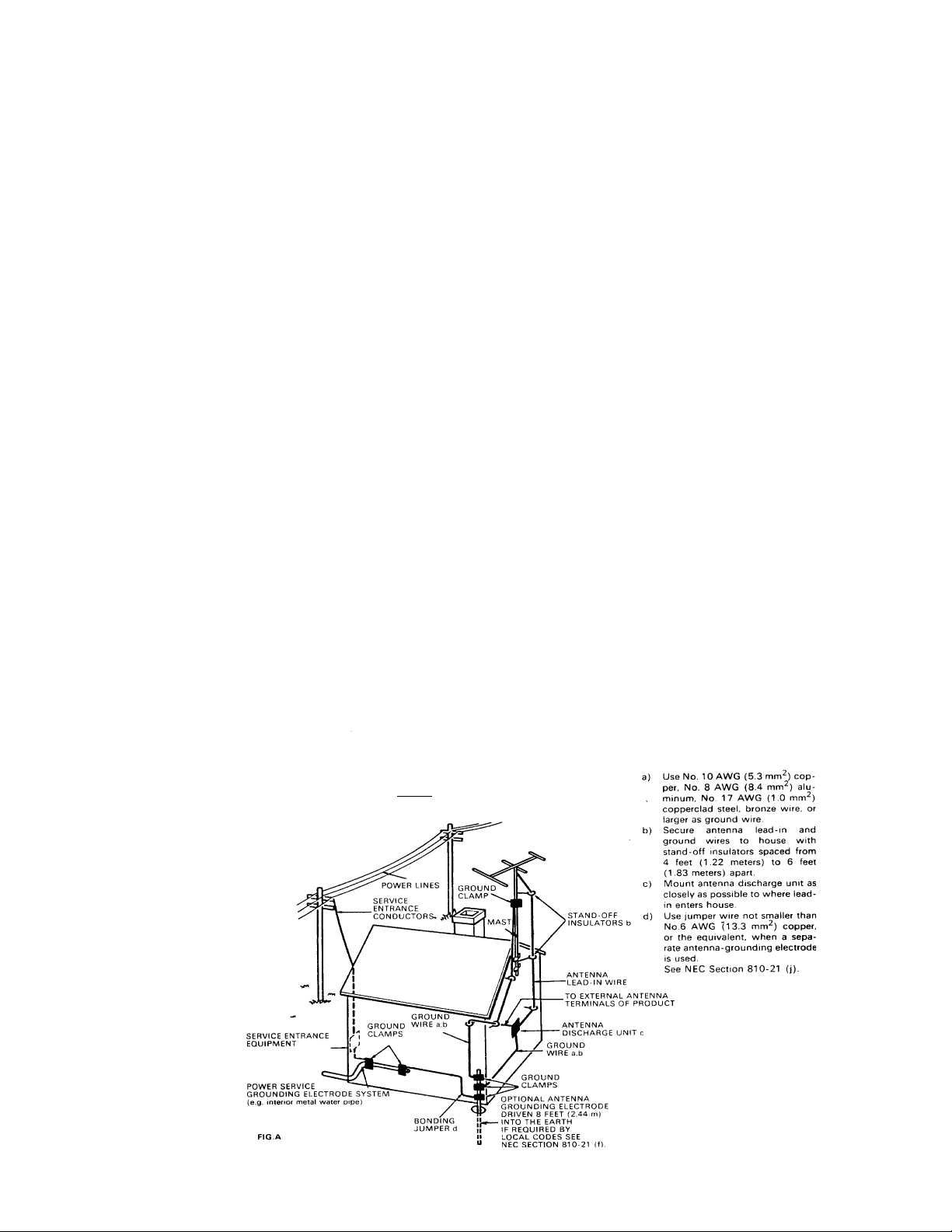
POWERLINES-Anoutdoorantennashouldbelocatedawayfrom
power lines.
PERIODSOFDISUSE-Thepowercordoftheappliancesshould
be unplugged from the outlet when the units are not in use for a
long period of time.
OBJECTANDLIQUIDENTRY-Careshouldbetakensothat
objects do not fall and liquids are not spilled into the enclosures
through openings.
DAMAGE REQUIRING SERVICE - The appliances should
be serviced by an authorized service center or qualified service
personnel when:
• The power supply cords or plugs have been damaged; or
• Objects have fallen, or liquid has been spilled into the
appliances; or
• The appliances have been exposed to rain; or
• The appliances do not appear to operate normally or
exhibit a marked change in performance; or
•Theapplianceshavebeendropped;ortheenclosureshave
been damaged.
SERVICING-Theusershouldnotattempttoservicetheappliances
beyondthatdescribedintheoperatinginstructions. Forallother
servicing, contact the factory.

4
Description of the DELTA System
ADA's DELTA System is a multi-room/multi-source system that utilizes ADA's
exclusive ADA Bus™ Bi-Directional serial data network. The Delta-88 acts as both a source
selector,preamplifier,and amplifier. Apartfrombeingthe ultimateinmulti-room technology,
the Delta System will operate perfectly as an audio-video selector when one zone (two, or up
to 256 zones) is set up as a home theater using ADA's SSD-66 Dolby ProLogic® Surround
SoundDecoder orSSD-66THX HomeTHX® Controller.The useris able toselect audiosources
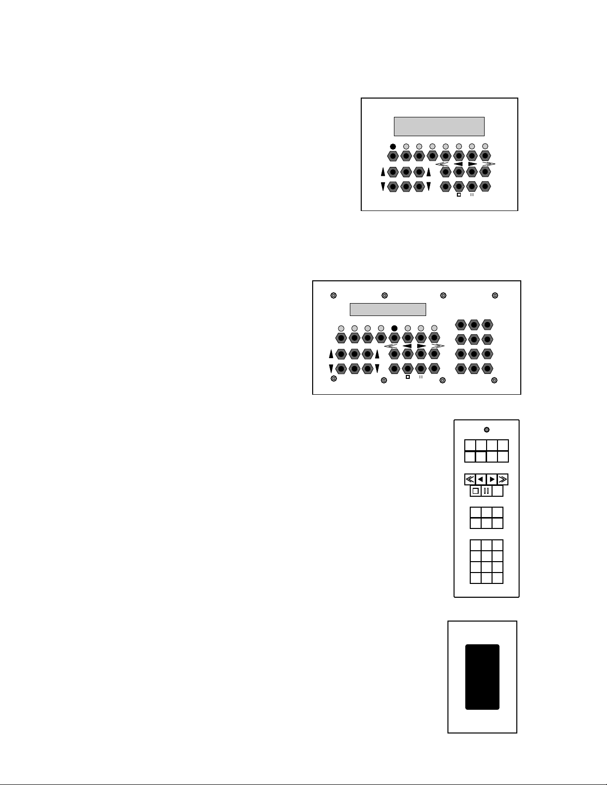
(and video sources when using the VSM-8 Video Switching Module) with the MC-3000 Music
Control, MC-3011 Decora® Style Keypad (Single Gang), MC-3800 Music Control with Nu-
meric Direct Access (triple gang), MC-3000 OD All Weather Outdoor Keypad, or MC-0038
Hand-Held IR Remote for that zone, while other zones can select their own source (from their
own keypads or IR remotes). All of the information that appears on the L.E.D. display of the
Delta-88 (and MT-3000, SSD-66, PCT-4, or PCT-8 if used) will also appear on the MC-3000
Series controls, so the user is aware of the system's status at all times without having to be in
front of the rack of equipment. From MC-3000's and MC-3800's, the user can also access other
rooms and turn them on or off, program a source to those rooms, and even adjust the other
room's volume level.
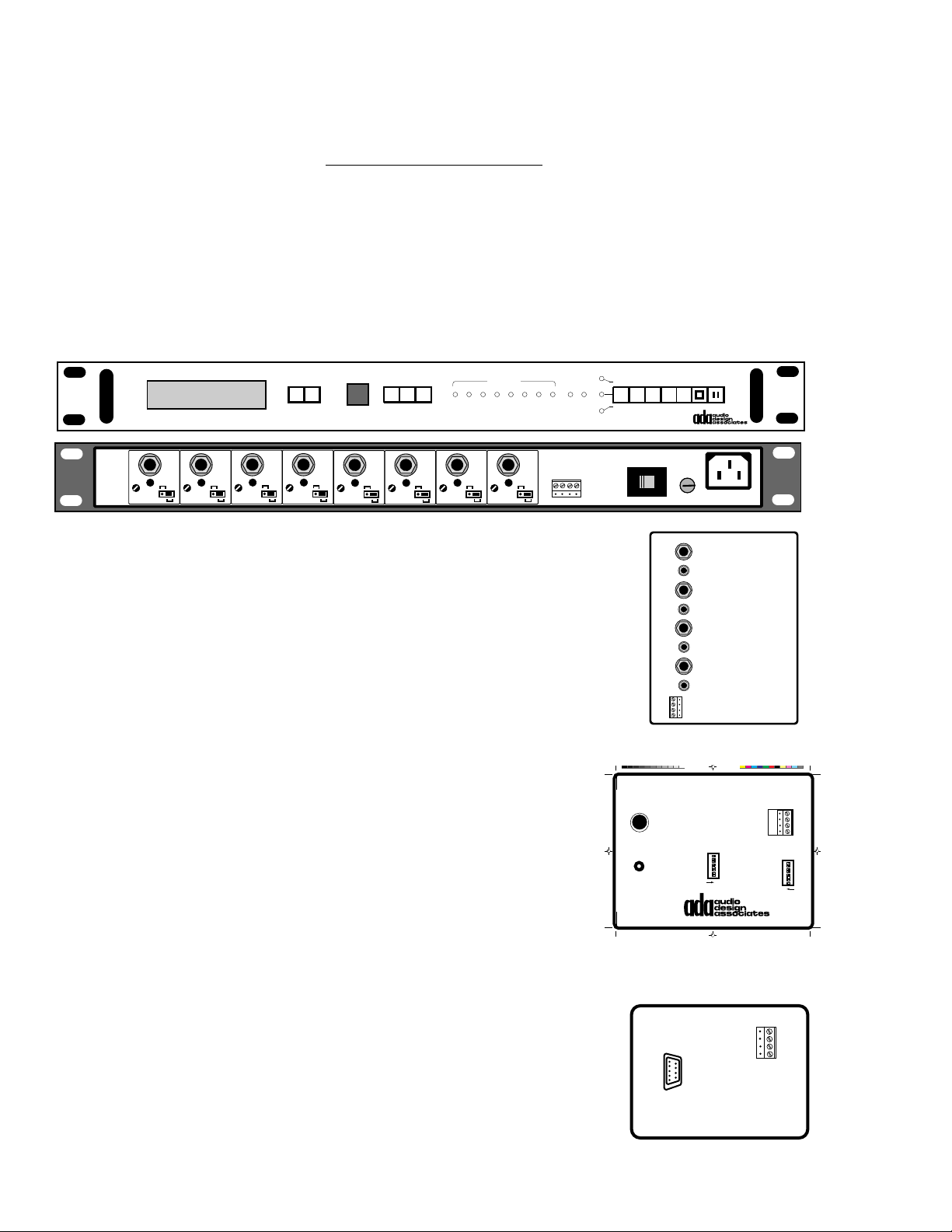
DELTA-88 System Controller•an ADA Bus™Component • isthe heartof the DeltaSystem.
Asmanyas32 Delta-88s canbestackedtogetherto provide atotalof256possible rooms/zones.
TheDelta-88can houseuptoeightcards (RAM-50RoomIntegratedAmps, RBM-50RoomBass
Amps, or VSM-8 Video-follow-Audio Switcher {one per Delta-88 max}). From the front panel,
the Delta-88 permits control of all rooms, room acoustical preset programming, and system
programming. The Delta-88 also provides the power supply for the room amplifiers (RAM-
50s and RBM-50s) and is fully fanned cooled. The Delta-88 can accept up to eight sources for
direct access from any 3000 Series keypad. If video sources are included among these eight
sources for composite video distribution, a VSM-8 Video-follow-Audio Switching Module
will be required so that the video sources' composite video outputs connect to the Delta-88.
When using several Delta-88s to form a system, sources are connected to the first Delta-88 and
the additional Delta-88s are connected to the first Delta-88 with a ribbon cable (System Bus).
This ribbon cable sends balanced audio signals to all other Delta-88s. Composite video signals
will need to be split (use an ISO-V Video Isolation Amplifier) to both Delta-88s' VSM-8s. When
using up to seven audio only sources and as many as eight video sources with the need for
composite video switching and/or keypad control of the video sources, use the VS-3 as an
alternate scrolling input selector (see pages 44-55).
FM TUNER 1
FM 1 FM 2 AM CD 1 CD 2 AUX CASS
1CASS
2
ROOM
OF
BASS
UP
BASS
DN
VOL
UP
VOL
DN
TREBLE
UP
TREBLE
DN
BAL
L
BAL
R
LOUD
STORE
ENHAN
STEREO
LABEL
FAMILY ROOM
ROOM 1 ROOM 2 ROOM 3 ROOM 4 ROOM 5 ROOM 6 ROOM 7 ROOM 8
ALL
MAIN
ON
OFF
DELTA-88
SOURCES ROOMS

5
RAM-50 Room Amplifier Modules are used as needed, one RAM-50 for each
room/zone. The amplifier provides 50 Watts per channel and is stable
down to 4Ω. Each RAM-50 also provides: a fixed line-level output for use
with surround decoders (SSD-66 or SSD-66THX Decoders); a variable line-
level output for use with external power amplifiers for greater power (PF-
250,250W/Ch Amp)or when driving an impedanceload below4Ω(PF-200,
1/2Ωstable power amp); and banana pin speaker jacks. For rooms which
may need more amplification than a single RAM-50 can provide, several
RAM-50scanbeslavedoffofamainRAM-50whiletrackingthesamesource
and acoustical settings. While a single Delta-88 can hold up to eight RAM-
50s, you can assemble the Delta-88 with exactly the right number of RAM-
50s to suite your particular project. Any unused slots in the Delta-88 are
available for future zones.
RBM-50 Room Bass Amplifier Modules are used for rooms that have a passive
subwoofer. The RBM-50 can be pre-ordered to a specific frequency roll-off
pointand provides100 Wattsofsubwoofer powerstable downto 4Ω. When
using a RBM-50, the signal to the bass amplifier is derived from a RAM-50's
variable line level output. Even though the RBM-50's bass level is set in
software, once set, the bass level will track the RAM-50's volume
(room's volume level). The RBM-50 will take the space of one RAM-50
in the Delta-88. Thus, using one RBM-50 in a single Delta-88, will leave
space in the Delta-88 for up to seven RAM-50 Room Amp Cards.
VSM-8 Video Switching Modules are available for providing com-
posite video-follow-audio switching within the Delta-88. A single
VSM-8 takes a card slot inside the Delta-88. Thus, using one VSM-8
(only one per Delta-88) in a single Delta-88, will leave space in the Delta-88 for up
to seven RAM-50 Room Amp Cards. A single VSM-8 can provide switching of up
to eight video sources to up to seven zones. When using several Delta-88s to make
up a system where each zone requires composite video switching, each Delta-88
will require one VSM-8.
Description of the DELTA System (cont.)
FIX
VAR
SPEAKER
LR
+
-
LINE
RAM-50
1
2
3
4
5
6
7
8
AUDIO
INPUTS
FIX
VAR
SPEAKER
LR
+
-
LINE
RAM-50
FIX
VAR
SPEAKER
LR
+
-
LINE
RAM-50
FIX
VAR
SPEAKER
LR
+
-
LINE
RAM-50
FIX
VAR
SPEAKER
LR
+
-
LINE
RAM-50
FIX
VAR
SPEAKER
LR
+
-
LINE
RAM-50
FIX
VAR
SPEAKER
LR
+
-
LINE
RAM-50
432121
ADA BUS™
MUTE L.V.
ZONE L.V.
OUT
AC INPUT
AC
LOOP OUT
TO DELTA-88
12
12
3 4
34
5 6
56
78
78
VSM-8
VIDEO SWITCHER
V
I
D
E
O
I
N
P
U
T
V
I
D
E
O
O
U
T
P
U
T
FIX
VAR
SPEAKER
LR
+
-
LINE
RAM-50
LOOP
L
SUB
LR
+
-
R
BRIDGED
RBM-50
12
12
3 4
34
5 6
56
78
78
VSM-8
VIDEO SWITCHER
V
I
D
E
O
I
N
P
U
T
V
I
D
E
O
O
U
T
P
U
T

6
The previous items are used to build a Delta-88. The following components are external to the
Delta-88 and can be used to create a full Delta System.
System & Source AC Control
The Delta-88 is the heart of the Delta System but AC switching of home theater systems,
external power amplifiers, and even the source components must use either an ACC-
3 and DB-9, ACC-48, or ACC-3000.
ACC-3000 Source AC Controller • an ADA Bus™ Component • is used for to provide smart
AC switching to each source. If a source is selected on the Delta-88, the ACC-3000 will
turn it on. This ideal operation extends the life of source components while permitting
true one-button operation of Tuners, CD players, and Cassette Players. Using CDs and
Cassette Players with a timer play function, mere selection of that source from either the
Delta-88 or a keypad will turn on that room, turn on that source, and automatically
engage play. To determine if your source component incorporates timer/play, either
locate a switch marked timer/play or: turn the source on, engage it into play, unplug
the source component while in play, plug the source component back into an AC outlet,
and wait 5-10 seconds. If the source has automatic timer/play, it will resume playing
automatically.
ACC-48 Basic AC Controller can be configured to provide one, two, or three different AC
controlling tasks. Designed as an inexpensive way to
provide AC switching, the ACC-48 has four AC
outlets which are triggered via the 9 pin ribbon cable
that connects to the Delta-88's 9 pin "D" connector.
Each AC outlet has a corresponding jumper pin bank
of eight plugs. These eight plugs determine when
that AC outlet turns on. Furthermore, the Delta-88
hasastepinitssetupprogramwhichsetsthefunction
of its 9 pin "D" connector. These options exist
Option 1 - Source Tracking. When the Delta-88's 9 pin "D"
connector is set to source tracking (in software), the ACC-48's AC outlets will engage on
and off with respect to the sources in use on the Delta-88. Thus an ACC-48 can provide
basic independent AC control of up to four sources. Two ACC-48s could provide basic
independent AC control of eight sources. When using the MT-3000 Multi-Tuner, the
MT-3000typically acts asthree of theeight sources onthe system. Therefore,if you only
Description of the DELTA System (cont.)
1234
5678
RECEIVING DATA TRANSMITTING DATA READY
ACC-3000
1234
ACC-3000
FUSE
AC POWER SWITCHED B SWITCHED A 87654321
ADA BUS
ACC-3
12345678 TO 9 PIN "D"
DELTA-88123456781234567812345678
1000 WATTS
MAX TOTAL
Set Shunting Pins To EngageAC With Zone Or Source Numbers 1-8
120-240 VAC
50-60 Hz
QUAD AC CONTROLLER
ACC-48
CAUTION
RISK OF ELECTRIC SHOCK
DO NOT OPEN
ATTENTION!
RISQUE DE CHOC ELECTRIQUE.
NE PAS OUVRIR
MADE IN U.S.A.
1. Delta-88 9 Pin "D" programmed for source AC control. - Set one shunting
pin per AC outlet according to source inputs. Set 3 pins for MT-3000.
2. Delta-88 9 Pin "D" programmed for zone AC control. - Set one shunting
pen per AC outlet according to zone numbers. Set all shunting pins on
one AC Outlet for All-On source AC control when not using anACC-3000.
3421
ACC-48 w/Holes 1/24/95, 9:09 AM1

7
Description of the DELTA System (cont.)
have three other sources in addition to the MT-3000, a single ACC-48 can be used. The
AC outlet for the MT-3000 would have three jumper pins in it bank in correspondence
with the inputs it takes up on the Delta-88. The remaining three sources will plug into
the other three AC outlets with their respective jumper pin banks set with a single
jumper in correspondence to the sources' connection to the Delta-88.
Option 2 - Zone Tracking. When the Delta-88's 9 pin "D" connector is set to zone tracking (in
software), the ACC-48's AC outlets will engage on and off with respect to a zones use
on the Delta-88. Thus an ACC-48 can provide independent AC control to up to four
zones. This device is used when including a home theater system on a particular zone
or external power amplifier on a particular zone. Please note that the ACC-48 can
handle a 10 amp load. If the total four outlets will draw more than 10 amps, additional
ACC-48s will be needed. You can slave several ACC-48s off of the Delta-88's 9 pin "D"
connector. *When working with a tight budget, a single ACC-48 can be used to provide
all sources on at once AC switching on one outlet with the remaining three outlets used
to provide independent room amplification AC control. **If you are using more than
one Delta-88 and have auxiliary amplifiers on both Delta-88s, you will need one ACC-
48 per Delta-88.
Option 3 - Zone Tracking & Source Tracking. The Delta-88 can be modified to accommodate
a second 9 pin "D" connector which provides only zone tracking. This connector and an
ACC-48 would provide amplifier/theater AC switching. The standard 9 pin "D"
connector would be set to source tracking (in software) and be used with ACC-48(s) for
independent source AC switching.
ACC-3 Single AC Controller is capable of providing a switched AC outlet (two AC outlets
rated at 15 amps per ACC-3) when it receives one of
two low voltage triggers. It is connected to the Delta-
88 using a DB-9 9 Pin "D" to Screw Terminal connec-
tor. If you are using a Delta-88's 9 pin "D" connector
for zone tracking, a single DB-9 is used per Delta-88
with any number of ACC-3s to power large external
amplifiers. Since the ACC-3 has a 15 Amp rating, it
may be more conducive for systems using several
largeamplifiers inplace ofan ACC-48(10 Ampmax).
ACC-3
1234
-A+ -B+
8
Description of the DELTA System (cont.)
1234
PCT-8
FUSE
AC POWER
ADA BUS
115 V
VOLTAGE
CARRIER
DATA
CARRIER
LEVEL
5VDC
PULSE
INPUT
1
CARRIER
DATA
CARRIER
LEVEL
5VDC
PULSE
INPUT
2
CARRIER
DATA
CARRIER
LEVEL
5VDC
PULSE
INPUT
3
CARRIER
DATA
CARRIER
LEVEL
5VDC
PULSE
INPUT
4
CARRIER
DATA
CARRIER
LEVEL
5VDC
PULSE
INPUT
5
CARRIER
DATA
CARRIER
LEVEL
5VDC
PULSE
INPUT
6
CARRIER
DATA
CARRIER
LEVEL
5VDC
PULSE
INPUT
7
CARRIER
DATA
CARRIER
LEVEL
5VDC
PULSE
INPUT
8
DATADATADATADATADATADATADATADATA
MADE IN U.S.A.
PCT-8
1 2 3 4 5 6 7 8 RX TX
IR CODE PORT ADA BUS™ 0123456
789
*
E
NTER
O
N
O
FF
PROGRAM
MENU ENTER
MAIN
<< < > >>
NEXTDN UP
PULSE IN 1
CODE OUT 1
PULSE IN 2
CODE OUT 2
PULSE IN 3
CODE OUT 3
PULSE IN 4
CODE OUT 4
1
2
3
4
GND
TX DATA
RX DATA
+15VDC
PCT-4
PULSE-CODE
TRANSLATOR
PDF-3000
Pioneer PDF-100 & PDF-107
CD Library Controller
TO
PD-F100
OR
PD-F107
I/O DATA
TO
CONTROL IN
ADDRESS
SW 2 ADDRESS
SW 1
1
2
3
4
5
6
7
8
PWR
3
2
TEST
LEDs
4
3
2
1
8
7
6
5
4
3
2
1
ON
ON
ADA BUS™
PDF-3000 w/Holes 1/25/95, 5:27 PM1
ADA BUS™
BC-232
4
3
2
1
RS-232
Source Transport Control
PCT-8 Source Controller • an ADA Bus™ Component • Will control up to eight sources via
IR or Serial Data with 19 transport functions per source. Sources can be programmed
on site. Pre-programmed EEPROM Chips for a particular manufacturer (i.e. Pioneer,
Sony) are available from ADA at an nominal fee. The PCT-8 has two address settings
to correspond to the eight direct source buttons on the MC-3000 Series keypads and has
several additional address settings to track the source selected on a VS-3 for scrolling
input selection and source control.
PCT-4 Source Controller • an ADA Bus™ Component • One PCT-4
will control up to four source components via IR or Serial data
with seven transport functions per source. Sources must exist in
the PCT-4 Library.
PDF-3000 • an ADA Bus™ Component • is used to control and read
Pioneer PD-F100 and PD-F107 100 Disc CD Changers. Using the
CD changers scuzy port, the playing disc and track number will
display on all MC-3000 and MC-3800 keypads listening to that
source. Even if you change discs and tracks directly on the
CD Changer, the keypads will update to the newly selected
disc and track numbers. Up to eight 100 disc changers can
be included on any one system (as direct access sources only
- no VS-3 scrolling source selection) with as many as eight
PDF-3000s. The PDF-3000 will also take the place of a port
on the PCT-8 or PCT-4 for CD Changer Control.
BC-232 • an ADA Bus™ Component • This device permits the ADA Bus™ to interface with
RS-232 components such as, AMX or Crestron Touch Screens, Gefen Systems CD and
Laserdisc Computer Management Software Systems, home
automation systems, personal IBM based computers, and
additional devices capable of controlling or being controlled
via RS-232 Data. New manufacturers are constantly integrat-
ingthe latest technologieswith theADA Bus™. Please consult
with ADA regarding a particular application.

9
MT-3000 Multi-Tuner - 3 Broadcast Sources in One Chassis
MT-3000 Multi-Tuner • an ADA Bus™ Component • is used as up to three broadcast sources
in any configuration (FM/FM/AM, FM/TV/TV, etc.) The MT-3000 fully integrates
with MC-3000 Keypads on the ADA Bus™ to provide complete feedback in the form of
station frequencies with programmable preset labels. When selecting a tuner module,
thekeypad will displaythe same informationdisplayed on theMT-3000. While the MT-
3000 acts as three sources, it has only one AC power cord and will need to be turned on
when either sources 1, 2, or 3 are selected from a keypad. You can turn the MT-3000 on
using either an ACC-3000 or ACC-48. Also see FMA-1 and AMA-1 MT-3000 Tuner
Accessories below.
FMA-1 & AMA-1 • an MT-3000 Accessory • The FMA-1 is a remotely controlled FM Antenna
Preamplifier (not an FM antenna) and works in conjunction with the MT-3000 Multi-
Tuner's FM Tuner Modules. Typically, the FMA-1 is used when the FM antenna is
located away from the equipment mainframe. The FMA-1 should be located near the
antenna location and requires an RF Cable and 2 Conductor/18 Gauge w/Stranded
Shield control cable run from it to the MT-3000. Every time the user changes FM
stations,the FMA-1 istold which frequencythe tuner isset forand thereby preamplifies
that particular frequency rather than the entire bandwidth. The end result is a more
finely tuned FM signal, preamplified prior to sending the signal through electronically
noisy environments. The AMA-1 AM Antenna and Antenna Preamplifier works
similar to FMA-1, except the AMA-1 is also an AM Antenna in addition to an antenna
preamplifier. This unit should also be located away from electronically noisy environ-
ments (typically an attic space). When using FMA-1s and/or AMA-1s, you will need
to run individual control cables and RF cables for each FM and/or AM Modules. In
typical Delta Systems, where the MT-3000 Tuner Module format is FM, AM, TV, you
will need one FMA-1 and one AMA-1, each with its own RF and Control Cable run to
the MT-3000. Please note, if you wish to use antenna preamplifiers, you will need one
FMA-1 or AMA-1 for every MT-3000 FM Module or AM Module. If your source format
is FM 1, FM 2, AM, you will require two FMA-1's and one AMA-1, each with its own RF
cable and control cable run to the MT-3000.
Description of the DELTA System (cont.)
TUNE
DN TUNE
UP
MONO DNB
MUTE DISPLAY
97.60 JAZZ CH 32 MTV
FM AM TV
FINE
DN FINE
UP SEEK
DN SEEK
UP PRESET LABEL STORE
MT-3000
MADE IN THE U.S.A.
SOLID STATE SCOPE
STEREO STEREO STEREO
1010 NEWS
ON
OFF
1
2
ST
115 V
1
2
3
4
1
2
3
4
1
2
3
4
MULTI-TUNER
MT-3000
AUDIO OUT
LR
AUDIO OUT
LR AUDIO OUT
LR AUDIO OUT
LR
ADA
BUS REMOTE REMOTE REMOTE
ANT PRE-AMP ANT PRE-AMP ANT PRE-AMP
ANT IN ANT IN ANT IN
COMBINED
OUTPUT TUNER 3 TUNER 2 TUNER 1
VOLTAGE SELECTFUSE
AC POWER V
10
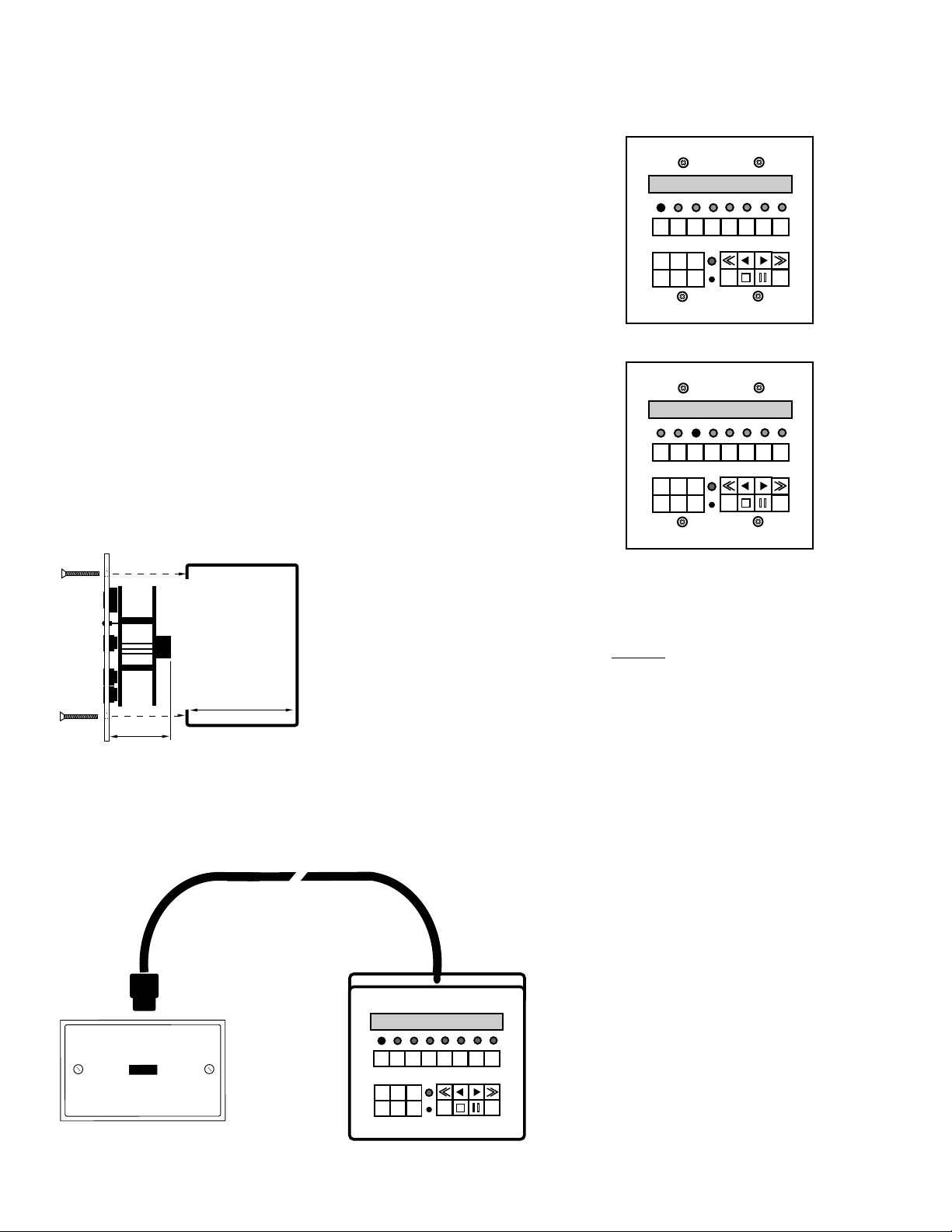
MC-3000 Room Keypad • an ADA Bus™ Component • One
keypad is needed per zone and will control source selection,
seven source transport commands, room volume, bass and
treblelevels (whena zoneis ahome theater{using anSSD-66}
the MC-3000 Keypad will control Volume Preset, Time De-
lay, Stereo Enhance, and Mode Selection), room off, and
system off. When keypads have been off for ten seconds, the
keypad will display the time. The MC-3000 also incorporates
an IR Receiver which can be used to IR repeat any source's
original hand-held remote (sources must operate on a 35-
45KHz IR). If the keypad receives sunlight or a great deal of
incandescent light, ADA recommends turning the IR emitter
andreceiveroff. Thiscanbedoneonce thekeypad isinstalled
since it is software controlled. If you anticipate a problem
with the location of the MC-3000 with respect strong lights or
sunlight, plan to include an IRT-3000 IR Transceiver (single-
gangDecora)somewhere elseintheroomor relocatetheMC-
3000. The IRT-3000 has a filter lens.
The MC-3000 Keypad fits into a
double-gangwall box andis available inBrass, Chrome, Black
Chrome, Black Anodized, or painted White. The wall plates
rest on top of the walls surface and do not provide any play
once installed into a wall box. Wall boxes will need to be
mounted perfectly square or the keypad, once installed, will
appear crooked.
MC-3000T Table Top Keypad • an ADA Bus™ Component • The MC-3000 all metal Table
Top Keypad is available in Brass, Chrome, or painted black or white, and has a slim
controlcordwith amodularconnector. Theboxis angledandpermitsthe clienttomove
the keypad to an optimum position when seated. When using the MC-3000T, you must
plug its slim cord with modular jack into a WPA-3000 Wall Plate Adaptor. The WPA-
3000 fits into a single-gang wall
box and comes unfinished in a
brushed aluminum wall plate
ready for painting or wall paper.
ADA strongly recommends add-
ing an IRT-3000 IR Transceiver
to any room which only has an
MC-3000T when IR repeating is
required. The MC-3000T's, IR re-
ceiver/transmitter is usually
turned off to prevent IR interfer-
ence on the ADA Bus™, since the
MT-3000T is usually on a table
top, underneath a lamp.
Description of the DELTA System (cont.)
ROOM
OFF
101.90 JAZZ
BASS
UP
BASS
DN
VOL
UP
VOL
DN
TREBLE
UP
TREBLE
DN ROOM
OFF
SHIFT
FM 1 AM TV VCR
1VCR
2LASER CD CASS
Slim Control Cable - 6'
ROOM
OFF
97.60 JAZZ
FM AM TV CD CASS
VCR
2LASER
BASS
UP TREBLE
UP
VOL
UP
VOL
DN BASS
DN TREBLE
DN ROOM
OFF
SHIFT
VCR
1
ROOM
OFF
CH 32 MTV
FM AM TV CD CASS
VCR
2LASER
MODE DELAY
VOL
UP
VOL
DN VOL
PRESET MON
ENHAN ROOM
OFF
SHIFT
VCR
1
Home Theater MC-3000
Standard MC-3000
Custom Modular Connector
WPA-3000 Wall Plate Adaptor
1-3/4"
2-3/4"
DOUBLE
GANG
MASONRY
BOX

11
Description of the DELTA System (cont.)
MC-3800 Keypad with Numeric Source Control • an ADA Bus™ Component • This control
option permits the client to control source components with twelve additional numeric
transport commands in addition to the MC-3000's seven transport functions. You must
be using the PCT-8 in order to access these additional numeric transport functions. This
keypad also offers six additional buttons for low voltage controls (when using an LVI-
3800 for lighting, screen, curtain control, etc.).
MC-3800 can also be purchased as an MC-3800T
Table Top Control and will require a WPA-3000
Wall Plate Adaptor. The MC-3800 Keypad fits
into a three-gang wall box and is available in
Brass, Chrome, Black Chrome, Black Anodized,
or painted White. The wall plates rest on top of
the walls surface and do not provide any play
once installed into a wall box. Wall boxes will
need to be mounted perfectly square or the key-
pad, once installed, will appear crooked.
MC-3011 Decora Style Delta System Keypad • an ADA Bus™ Component • The MC-3011
Keypadpermits directaccess ofany source,control ofvolume, roomoff, andsystem off.
In addition to these standard functions, the MC-3011 also permits the
control of five transport commands per source. The first transport
functionisaccessed whenthesourcebutton isrepeatedlypressed and
typically permits tuner preset skip, disc skip, and cassette skip. The
remaining four functions typically include fast forward and fast
rewind buttons (track skip up and down, tune up and down), stop,
play. The MC-3011 does not include an alphanumeric display or
built-in IR transceiver. LED indicators do show which source is
playing or if a zone is on elsewhere when that room is off. The MC-
3011 is programmed through DIP switches and cannot access infor-
mation or control other rooms like the MC-3000.
MC-3800RF Keypad with Bi-Directional RF Wireless Control • an ADA Bus™ Component
•ThiscontroloptionpermitstheclienttocontrolsourcecomponentsusingtheMC-3800
ina completelywireless formatwith fulltwo-way communicationand feedback. Using
an RF-3000 Transceiver, the MC-3800RF is housed in a wooden enclosure and comes
with a transformer for recharging. Full recharge time takes 1.5 hours and the MC-
3800RF will run continuously for 2.5 hours (we used a screw driver jammed into a
button to test the batteries real-continuous usage
life). Actual time between recharges will be
significantly longer (several weeks) since the
MC-3800 will automatically time out if no but-
tons are pressed. This keypad also offers six
additionalbuttonsfor lowvoltagecontrols(when
using an LVI-3800 for lighting, screen, curtain
control, etc.). The MC-3800RF is available with a
Brass, Chrome, Black Chrome, Black Anodized,
or painted White face plate and wooden table-
top box options vary in wood type.
ROOM
OFF
101.90 JAZZ
FM 1 FM 2 AM CD
1CD
2AUX CASS
1
BASS
UP
BASS
DN
VOL
UP
VOL
DN
TREBLE
UP
TREBLE
DN ROOM
OFF
SHIFT
8
0
7
*
9
ENTER
2
5
1
4
3
6
CASS
2
ON
OFF
ON
OFF
ON
OFF
FM 2 AM
CD
2
CD
1
CASS
1CASS
2
TREBLE
UP
TREBLE
DN
MAIN
OFF
FM 1
AUX
ROOM
OFF
101.90 JAZZ
FM 1 FM 2 AM CD
1CD
2AUX CASS
1
BASS
UP
BASS
DN
VOL
UP
VOL
DN
TREBLE
UP
TREBLE
DN ROOM
OFF
SHIFT
8
0
7
*
9
ENTER
2
5
1
4
3
6
CASS
2
ON
OFF
ON
OFF
ON
OFF
12
MC-3000 OD • an ADA Bus™ Component • The MC-3000
OD is an all weather outdoor keypad complete with a
twelve character alphanumeric LED display. All func-
tions are identical to the MC-3000 except the MC-3000
OD does not have an IR transmitter and receiver. The
MC-3000 OD fits a Mulberry 30601 Three Gang Out-
door Box and should be sealed to the box with silicon.
For custom source formats, the MC-3000 OD will re-
quire a custom silk screen provided at a nominal fee.
All MC-3000 ODs come in a white wall plate.
MC-3800 OD • an ADA Bus™ Component • The MC-3000 OD is an all weather outdoor
keypad complete with a twelve character alphanumeric LED display and direct access
numeric buttons. All functions are identical
to the MC-3000 except the MC-3000 OD does
not have an IR transmitter and receiver. The
MC-3800 OD fits a Four Gang Outdoor Box
and should be sealed to the box with silicon.
For custom source formats, the MC-3800 OD
will require a custom silk screen provided at
a nominal fee. All MC-3800 ODs come in a
white wall plate.
MC-0038 Hand-Held Infrared Remote Control • an ADA Bus™ Component
• The MC-0038 is a full function remote control which offers the same
functions as the MC-3800 hard-wired keypads. The MC-0038 is zone
specific in that it is programmed, much like a MC-3800, to control a
specific zone. Yet, unlike the MC-3800, the MC-0038 cannot access any
other room. Since all ADA IR Transceivers, whether they are on the MC-
3000or IRT-3000,allconnect tothe samewiringharness, itis theMC-0038
which knows what room it is intended to control, not the IR receiver.
Therefore, if your client requires hand-held control in more than one
zone, specify several MC-0038s. When using an MC-0038, ADA strongly
recommends adding an IRT-3000 IR Transceiver to that room. If the
room has an MC-3000T Table-Top control, you will have to provide an
IRT-3000 and disengage the MC-3000T's IR transceiver.
IRT-3000 • an ADA Bus™ Component • This unit acts as both an IR Receiver
and Transmitter and fits into a single-gang Decora Wall Plate. The IRT-
3000 is the best device for receiving signals from a Delta-88 Remote and
particularly the MC-0038 IR Remote Control. It also works well as a
primary or secondary IR receiver for repeating a source component's IR
signals. This unit includes a Red Filter Lens which cuts down on IR
interference. For rooms with a great deal of ambient light (sunlight or
incandescent light) use an IRT-3000 and turn off the IR Transceiver on
the MC-3000 and MC-3800 Keypads.
Description of the DELTA System (cont.)
101.90 JAZZ
OFF
SHIFT
VOL BASS TREB
FM AM TV VCR 1 VCR 2 LASER CD CASS
OFF
SHIFT
VOL BASS TREB
FM 1 FM 2 AM CD 1 CD 2 AUX CASS1 CASS2
CD PLAYER 2
ROOM
OFF
FM 1 FM 2 AM CD
1
CD
2AUX CASS
1
BASS
UP
BASS
DN
VOL
UP
VOL
DN
TREBLE
UP
TREBLE
DN
ROOM
OFF
8
0
7
*
9
ENTER
2
5
1
4
3
6
CASS
2

13
Description of the DELTA System (cont.)
Assorted Support Hardware
WH-3000 ADA Bus™ Wire Harness • an ADA Bus™ Component • All ADA
Bus™ Components connect to this harness. The WH-3000 provides fuse
protection for short circuits which incorporate automatic reset. One WH-
3000 is required for every eight ADA Bus™ Components. If you are using
more than eight ADA Bus™ components, add one WH-3000 for every eight
additional devices.
BI-3000 ADA Bus™ Isolators • an ADA Bus™ Component • Isolates devices such
as MT-3000s and SSD-66s from picking up control data
noise. One unit is required for each MT-3000, SSD-66, and
SSD-66THX used in a Delta System. BI-3000s are also used
to isolate different ADA Networks which come into play
with larger more elaborate systems.
LVI-3800 Low Voltage Relay • an ADA Bus™ Component • This device can be used in a
variety of applications.
Option 1 - Zone Source Tracking - The LVI-3800 can be set to track
a specific zones source selection such that an AC controller
for a projector and screen (ACC-3) receives a control signal
to turn on only when a video source is selected. When an
audio source is selected or the zone is turned off, the
projectorwillturn off. Ifaprojector, screen,oreven aTVcan
be controlled via a switched AC outlet, the addition of an
ACC-3permits automaticAC controlof thevideo hardware
when only a video source is selected.
Option 2 - MC-3800 Softkey Contact Closure & Voltage - The LVI-3800 can be set so that the
extrasix buttonson theMC-3800Series controlstrigger momentaryswitches forcontrol
of lighting, curtains, etc. No other wire will need to be run to the keypad and the LVI-
3800 can be located anywhere in the house providing that an ADA Bus™ is run to its
location.
Option 3 - Source Transport Controller - The LVI-3800 can be set to control sources which do
not operate via IR or Serial Data. This application can only be done for one of the eight
sources and would permit as many as seven different functions for that source from the
keypads. These functions are translated to momentary low voltage relay closures
making this package ideal for control of a slide projector or other low voltage controlled
source.
UNIT CONTROL
BUS
BI-3000
1
2
3
4
4
3
2
1
1 2 3 4
WH-3000
1 2 3 4
J1
J2
J3
J4
J5
J6
J7
J8
J9
J10
LOOP THRU
8 7 6 5 4 3 2 1
8
7
6
5
4
3
2
1
REV
NORM RX/TX
SET
4
3
2
1
ADA BUS™
SW 2
SW 1
ON
ON
RELAY 1
RELAY 2
RELAY 3
RELAY 4
RELAY 5
RELAY 6
RELAY 7
RELAY 8
R1
R2
R3
R4
R5
R6
R7
R8
-
+5V
+12V
NORM. OPENNORM. CLOSED Carefully remove and insert relays
for changing from the Normally Open
to the Normally Closed position.
LOW VOLTAGE RELAY
LVI-3800
14
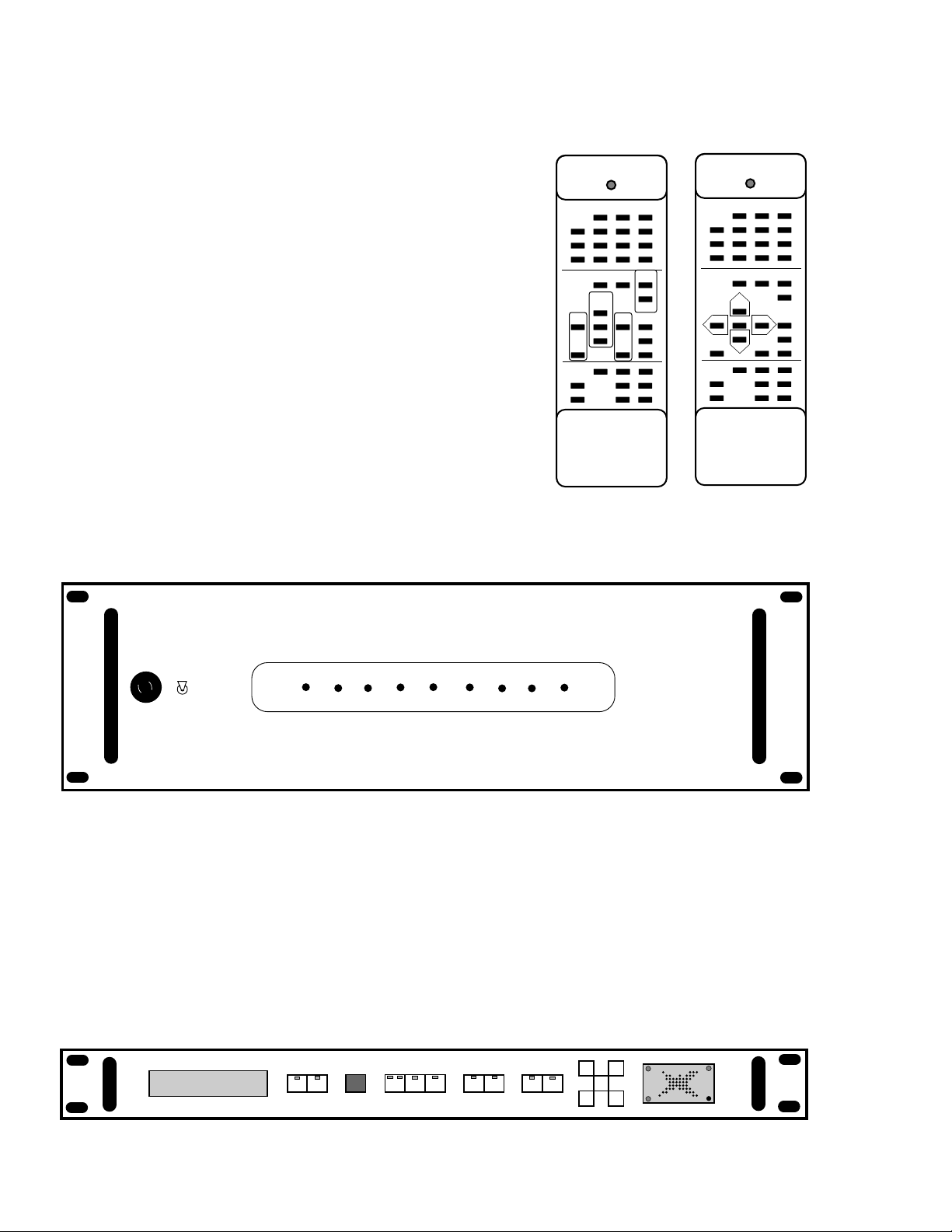
Delta-88 Hand-Held IR Remote • Can be used with the
Delta-88, MC-3000, and IRT-3000 (both have an IR
receiver) - The Delta-88 Remote incorporates 3 Room
Selectors which tells the Delta-88 which zone the
remote wishes to control (zones 1, 2, & 3 only). If the
zone is using the Delta-88's preamplifier stage, you
shouldspecify theStandardDelta-88 RemoteControl
overlay. If the zone is using an SSD-66 Surround
Sound Decoder for preamplification, you should
specify the Delta-88/SSD-66 Remote Control over-
lay.
PF-200 Low Impedance Power Amplifier - This amplifier
could be used for any zone with several speakers
pairs. The PF-200 is rated down to 1/2 Ωand is the
perfect amplifier when powering as many as sixteen
8Ωspeaker pairs on any one zone. Use an additional
ACC-3 so that the PF-200 powers up only when that
zone is on.
SSD-66 or SSD-66THX Surround Sound Controllers • an ADA Bus™ Component • can be
completelycontrolled from MC-3000,MC-3800, or MC-0038controls with fullfeedback
to the MC-3000 or MC-3800 Keypads. These keypads will display the same information
as displayed on the SSD-66. Since the SSD-66 will act as a zone's preamplifier, the SSD-
66 receives a fixed line-level signal from that zone's RAM-50 card. It is essential, that
when incorporating a home theater onto a zone, the home theater is its own zone with
no other rooms shared on that zone. Furthermore, each home theater must use its own
SSD-66 and each home theater will require a RAM-50 even though the cards amplifier
will not be used. Refer to "ADA's Guide To Home Theater Systems" (4 color brochure)
for selecting the appropriate home theater power amplifier.
Description of the DELTA System (cont.)
DELTA-3 AV 1 AV 2 OFF
AV 3 AV 4 ROOM 1
AV 5 AV 6 ROOM 2
AV 7 AV 8 ROOM 3
SSD-66 MUTE/OFF +
VOLUME
CENTER
LEFT ALL RIGHT VOLUME
PRESET
REAR DOLBY B NR
NOISE MONO
ENHANCE DELAY
MT-3000 TUNER 1 TUNER 2 TUNER 3
MONO/ST VS-3 VS-3
PRESET VS-3 VS-3
TUNING
-
AUDIO DESIGN ASSOCIATES
MODE
DELTA-3 AV 1 AV 2 OFF
AV 3 AV 4 ROOM 1
AV 5 AV 6 ROOM 2
AV 7 AV 8 ROOM 3
DELTA-3
PREAMP MUTE +
VOLUME
RIGHT UP
BASS
UP RESET TREBLE
UP PRESET
RECALL
LEFT UP LOUDNESS
BASS
DOWN TREBLE
DOWN ENHANCE
MT-3000 TUNER 1 TUNER 2 TUNER 3
MONO/ST VS-3 VS-3
PRESET VS-3 VS-3
TUNING
-
BALANCE
AUDIO DESIGN ASSOCIATES
Delta-3 Standard
Remote Control Delta-3/SSD-66
Remote Control
ON
OFF
POWER
PF-200
F
U
S
E
F
U
S
E
F
U
S
E
LEFT
ALL
REAR CENTER
RIGHT
OFF MODE VOL
UP VOL
DN
VOL
PRESET NOISEMONO
ENHAN DELAY DOLBY
NR REAR
PROLOGIC
15
Source Input Selection & Control Beyond The Standard 8 Sources
VS-3 Video Switcher (8 In x 3 Out) • an ADA Bus™ Component • can be used to provide
additional source inputs to the standard eight sources the Delta-88 can accept. The VS-
3 has multiple addresses, several of which permit the VS-3 to act as a source to the Delta-
88. This permits a system, loaded with seven audio only sources and up to eight video
sources, to access all fifteen sources from a 3000 Series keypad. The audio only sources
would be labeled what they are on the keypad's buttons. The video sources would all
be accessed through an eighth source button labeled VIDEO. Every time the VIDEO
button is pressed, the VS-3 advances to the next input. To provide the user with a sense
of where they are, the VS-3's display will appear on the MC-3000 or MC-3800 telling the
user what video source is selected to that room. Furthermore, the keypad's transport
buttons would correspond to the selected source (when using a PCT-8 Source IR
Controller for the video sources). Since a single VS-3 has three independent outputs, as
many as three rooms can independently and simultaneously select their own video
source using one VS-3. Each room's keypad will have the VIDEO button programmed
to control a specific VS-3 output and since the VS-3 has several addresses, multiple VS-
3s can be used to provide independent video switching to the entire house. Please note,
that the Delta-88 has only eight source inputs and since these are common to all zones,
special design considerations need to be considered when using the VS-3 as a scrolling
input selector. Several options exist and here are some examples:
Option 1 - The selected video source (can also be an audio only source) is common to all rooms,
noindependent simultaneous selection. Inthis scenario,a single VS-3is usedto expand
the system's source input capability. The VS-3's output is fed back into the Delta-88 on
the same source input number as it is on the keypad (i.e. AUX or VIDEO button). Every
time this button is pressed, the VS-3 will advance to the next source with the keypad
displaying that source's name (off the VS-3) and the transport functions operating that
source (use of a second PCT-8 Source IR Controller). Since the VS-3's output is fed back
into the Delta-88, the signal is common to all rooms which select that source.
Option 2 - The selected video source is independent to specific rooms or all rooms and video
sources are capable of being selected simultaneously. In the previous option, the VS-
3's output is fed back into the Delta-88 and is therefore common to the whole house. To
provide independent and simultaneous selection, you will need to use more than one
outputof the VS-3and perhapsseveral VS-3sto accommodate the entire house. Inthese
applications, the video signals and stereo audio signals need to be distributed to each
Description of the DELTA System (cont.)
OFF 1AV 1
VCR1 TO TV
2 3
OUTPUTS
AV
AV 2
AV
AV 3
AV
AV 4
AV
AV 5
AV
AV 6
AV
AV 7
AV
AV 8
AV
INPUTS
A/V
SPLIT
AV
RF 1
AB
RF 2
AB
RF 3
AB
LABEL
VS-3
3 L 2 L 1 L 8 L 7 L 6 L 5 L 4 L 3 L 2 L 1 L
S 3 S 2 S 1
V 3 V 2 V 1
3 R 2 R 1 R 8 R 7 R 6 R 5 R 4 R 3 R 2 R 1 R S 3 S 2 S 1S 4
V 8 V 7 V 6 V 5 V 4 V 3 V 2
RF 3 RF 2 RF 1 RF B RF A
FUSE AC INPUT
(50-60Hz 25W)
3/8A S.B.
250V
432121
+-
V 1
VS-3

16
remote room and each room keypad's VIDEO button would access a specific VS-3 and
VS-3 output. In this option, the TVs need to be switched to an external input to receive
the central sources. If the client wants to hear the audio through the same speakers
which are used for central music, a CCA-20 Current Sensing TV Amp & Speaker
Switcher or a CCS-3 Current Sensing Speaker Switcher should be used to override the
speakers with the output of the TV whenever the TV is on. If the room is a home theater,
a LLS-2 Line-Level Switcher should be used in conjunction with some type of voltage
controller(CCS-4 orLVI-3800) to trip the inputto theroom's surrounddecoder fromthe
fixed output of a room's RAM-50 to the fixed output of the local TV or central VS-3. The
output of the TV might be used instead of the VS-3, because the TV tuner's audio may
need to be decoded in addition to the centrally switched video sources.
Option 3 - This option is a combination of the previous two options such that a single VS-3 can
provide independent direct switching to two rooms using the VS-3 outputs 1 & 2 (i.e.
Theater and Master Bedroom) while the rest of the house accesses a common non-
simultaneous(independent) outputof theVS-3(output 3). Thetwo independentrooms
wire as in option 2 and the whole house wires as in option 1.
Option 4 - Using the VS-3 as a scrolling selector to gain transport control of video sources even
though the video sources are being modulated for distribution throughout the house.
In this application, the home could be broken into three areas when using one VS-3, to
gain independent control to the video sources over three areas simultaneously. Again,
this option could also be expanded using several VS-3s such that each room can access
a video source for keypad control independently of all other rooms.
Please note, ADA will introduce additional products which will operate with the Delta System.
Consult with your installer or ADA to find out what new products are available.
Description of the DELTA System (cont.)

17
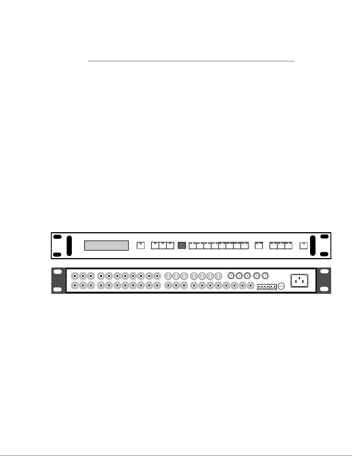
Audio Inputs
When looking at the rear panel of the Delta-88, the far right card is the
AIB-50 Audio Input Board. When stacking several Delta-88s to accommo-
date additional zones, only the first Delta-88 will have an AIB-50. The
remaining Delta-88s will have a blank panel and receive the sources line-
level audio signals via a 34 pin flat ribbon cable which is called the System
Bus. The System Bus connection is left unused in a system using only one
Delta-88. TheAIB-50 contains atotal ofeight stereoRCA jacks and is labeled
for sources 1 through 8 corresponding to the Delta-88's front panel sources
1through 8 readingleft to right. Thesources' audio outputsconnect directly
to the AIB-50 in the appropriate order. Please note, if you do not have a full
compliment of eight sources, take care to connect the sources on the
appropriate RCA jack.
Video Inputs
To permit the greatest flexibility for system design, the Delta-88 does
not come with a video switcher in its standard form. Because cards are added
only as needed, the Video-Follow-Audio Switching Module (VSM-8) is
available as an option. Only one VSM-8 is required per Delta-88 Chassis and
it can switch video to as many as seven zones. It is important to note, that the
VSM-8 takes the place of a zone's room integrated amp card (RAM-50) and
includingaVSM-8in a Delta-88willleavespaceavailable for onlysevenmore
zones.
Inmostsystemswhich
require two or more
Delta-88s,onlyahand-
ful of rooms may actu-
ally require video
switching. If for example, in a home
with 15 zones, perhaps only six or seven
of the zones have TVs. It is suggested to
group these zones with TVs on the first
Delta-88 with the VSM-8 card, while the
rooms that do not require video switch-
ing be grouped on the second Delta-88
that does not include a VSM-8 card.
When connecting video sources to the
VSM-8, please note that the numeric
inputssilk-screenedontheVSM-8panel
are slightly different from the AIB-50
Audio Input Board.
Delta-88 Connections
FIX
VAR
KER
R
+
-
50
1
2
3
4
5
6
7
8
AUDIO
INPUTS
TO DELTA-88
SPEAKE
L
LINE
RAM-5
S™
.V.
V.
PUT
OUT
12
12
3 4
34
5 6
56
78
78
VSM-8
VIDEO SWITCHER
V
I
D
E
O
I
N
P
U
T
V
I
D
E
O
O
U
T
P
U
T
FIX
VAR
SPEAKER
LR
+
-
LINE
RAM-50
1
2
3
4
5
6
7
8
AUDIO
INPUTS
FIX
VAR
SPEAKER
LR
+
-
LINE
RAM-50
FIX
VAR
SPEAKER
LR
+
-
LINE
RAM-50
FIX
VAR
SPEAKER
LR
+
-
LINE
RAM-50
FIX
VAR
SPEAKER
LR
+
-
LINE
RAM-50
FIX
VAR
SPEAKER
LR
+
-
LINE
RAM-50
FIX
VAR
SPEAKER
LR
+
-
LINE
RAM-50
432121
ADA BUS™
MUTE L.V.
ZONE L.V.
OUT
AC INPUT
AC
LOOP OUT
TO DELTA-88
12
12
3 4
34
5 6
56
78
78
VSM-8
VIDEO SWITCHER
V
I
D
E
O
I
N
P
U
T
V
I
D
E
O
O
U
T
P
U
T
115 V
1
2
3
4
1
2
3
4
1
2
3
4
MULTI-TUNER
MT-3000
AUDIO OUT
LR
AUDIO OUT
LR
AUDIO OUT
LR
AUDIO OUT
LR
REMOTE REMOTE REMOTE REMOTE
ANT PRE-AMP ANT PRE-AMP ANT PRE-AMP
ANT IN ANT IN ANT IN
COMBINED
OUTPUT TUNER 3 TUNER 2 TUNER 1
VOLTAGE SELECTFUSE
AC POWER
CD CHANGER
LASER
CASSETTE CHANGER
DSS
VCR AUDIO
VIDEO

18
Fixed Audio Line-Level Outputs
EachRAM-50RoomIntegrated
AmpModuleincorporatesafixedline-
level stereo audio output which can
be used to provide a fixed signal to
surround sound processors (SSD-66
or SSD-66THX). When connecting to
home theater systems, the RAM-50
for that zone acts as the input selector
while the decoder acts as the room's
preamplifier.
In certain cases, you may
be locating the surround
sound processor a signifi-
cant distance from the
Delta-88. When running
the fixed line-level audio
signal an extended distance or near high-voltage wires,
you may experience signal loss or ground loop hums
across the line-level signal. ADA provides two options to
improve audio levels or reduce/eliminate ground loop
hums. The first option includes the use of an ISO-2 Line
Level Isolation Amplifier which buffers the two channels
essentially providing each with its own ground. The
second option involves the use of ADA's XLRX-1 Unbal-
anced to Balanced Line Level Convertor and the XLRR-1
Balanced to Unbalanced Line Level Convertor. Place the
XLRX-1 on the transmitting end of the audio path and the
XLRR-1 on the receiving end of the
audio path. These devices will re-
quire a 2 conductor shielded wire run
for each channel.
Variable Audio Line-Level Outputs
EachRAM-50RoomIntegrated
Amp Module incorporates a variable
line-level stereo audio output which
can be used to provide an audio sig-
nal to external power amplifiers (PF-
200 or PF-250). When connecting to
external power amplifiers, the RAM-
50 acts as both the input selector and
preamplifier while its own internal
amplifier is left unused.
Delta-88 Connections (cont.)
FIX
VAR
SPEAKER
LR
+
-
LINE
RAM-50
1
2
3
4
5
6
7
8
AUDIO
INPUTS
FIX
VAR
SPEAKER
LR
+
-
LINE
RAM-50
FIX
VAR
SPEAKER
LR
+
-
LINE
RAM-50
FIX
VAR
SPEAKER
LR
+
-
LINE
RAM-50
FIX
VAR
SPEAKER
LR
+
-
LINE
RAM-50
FIX
VAR
SPEAKER
LR
+
-
LINE
RAM-50
FIX
VAR
SPEAKER
LR
+
-
LINE
RAM-50
4321 21
ADA BUS™
MUTE L.V.
ZONE L.V.
OUT
AC INPUT
AC
LOOP OUT
TO DELTA-88
12
12
3 4
34
5 6
56
78
78
VSM-8
VIDEO SWITCHER
V
I
D
E
O
I
N
P
U
T
V
I
D
E
O
O
U
T
P
U
T
ON
OFF
POWER
PF-200
F
U
S
E
F
U
S
E
F
U
S
E
FIX
VAR
SPEAKER
LR
+
-
LINE
RAM-50
1
2
3
4
5
6
7
8
AUDIO
INPUTS
FIX
VAR
SPEAKER
LR
+
-
LINE
RAM-50
FIX
VAR
SPEAKER
LR
+
-
LINE
RAM-50
FIX
VAR
SPEAKER
LR
+
-
LINE
RAM-50
FIX
VAR
SPEAKER
LR
+
-
LINE
RAM-50
FIX
VAR
SPEAKER
LR
+
-
LINE
RAM-50
FIX
VAR
SPEAKER
LR
+
-
LINE
RAM-50
4321 21
ADA BUS™
MUTE L.V.
ZONE L.V.
OUT
AC INPUT
AC
LOOP OUT
TO DELTA-88
12
12
3 4
34
5 6
56
78
78
VSM-8
VIDEO SWITCHER
V
I
D
E
O
I
N
P
U
T
V
I
D
E
O
O
U
T
P
U
T
LRLR
SUB
WOOFER CENTER LEFT RIGHT
115 V
VOLTAGE
SELECT FUSE
AC POWER
1 2 3 4
1 2
12VDC
ACC-2
- +
ADA
BUS
OUTPUTS
REAR FRONT
INPUT
LEVEL
MIN MAX
SSD-66
SURROUND
SOUND
DECODER
LR
XLRX-1
LR
XLRR-1
LR
LR
OUTPUT
INPUT
ISO-2 12V AC
TRANS-
FORMER
19
If you are locating the external power amplifier a considerable distance from the Delta-88,
follow the line-level suggestions on the previous page.
Stereo Speaker Jacks on the RAM-50
Each RAM-50 Room Integrated
Amp Module incorporates two banana
jack speaker connectors, one for the
rightchannel andthe secondfor theleft
channel. Please use the banana jacks
that are provided with the Delta-88.
The banana jacks have a small tab on
one of the polls marked GND for
ground. If you wire your speaker cable using the polarity tab as a
ground mark, connection to the Delta-88, even when you cannot
completely see the rear panel, is made significantly easier. Again,
make certain that the bannana jacks connect vertically to both the plus
and minus speaker outputs.
Each RAM-50 is stable down to 4Ωwhich means it can accept a speaker load of two pair of 8Ω
speakersor onepairof 4Ωspeakers. Anyload lowerthan4Ωwilleventuallydamage theRAM-
50 Amplifier Module. If you are connecting two pair of 8Ωspeakers, you can use a second set
of banana jacks to piggyback off of the first set connected to the Delta-88.
Bass Audio Input & Speaker Jacks (Only When Using the RBM-50 Bass Amp Module)
The RBM-50 is designed specifically to drive passive subwoofers with 100 Watts of
power. The subs are receiving a mono
audio signal derived from one of the
other zone amp cards (RAM-50s) on
the same Delta-88. The RBM-50 must
receive a variable line-level audio sig-
nal from the corresponding RAM-50
for that room so that the bass amp
raisesandlowersitsoutputalongwith
theroom's other speakers. Thereare additionalsettings
in software that permit the bass amps output level to be
settoaninitiallevel. Thiswillbediscussedinupcoming
sections of this manual.
Once you have connected a stereo line-level RCA wire from the corresponding RAM-50's
variable line-level output to the RBM-50's loop right & left (it does not matter whether you use
the upper or lower RCA jacks), you can connect the subwoofer's speaker wire to the RBM-50
using the bannana jacks that are provided. Since you can load the RBM-50 down to 4Ω, you
can connect two 8Ωsubs to the RBM-50. Again, you can piggyback the second sub on top of
the first subs banana jack.
Delta-88 Connections (cont.)
FIX
VAR
SPEAKER
LR
+
-
LINE
RAM-50
1
2
3
4
5
6
7
8
AUDIO
INPUTS
FIX
VAR
SPEAKER
LR
+
-
LINE
RAM-50
FIX
VAR
SPEAKER
LR
+
-
LINE
RAM-50
FIX
VAR
SPEAKER
LR
+
-
LINE
RAM-50
FIX
VAR
SPEAKER
LR
+
-
LINE
RAM-50
FIX
VAR
SPEAKER
LR
+
-
LINE
RAM-50
4321 21
ADA BUS™
MUTE L.V.
ZONE L.V.
OUT
AC INPUT
AC
LOOP OUT
TO DELTA-88
12
12
3 4
34
5 6
56
78
78
VSM-8
VIDEO SWITCHER
V
I
D
E
O
I
N
P
U
T
V
I
D
E
O
O
U
T
P
U
T
LOOP
L
SUB
LR
+
-
R
BRIDGED
RBM-50
Right
Left
FIX
VAR
SPEAKER
LR
+
-
LINE
RAM-50
1
2
3
4
5
6
7
8
AUDIO
INPUTS
FIX
VAR
SPEAKER
LR
+
-
LINE
RAM-50
FIX
VAR
SPEAKER
LR
+
-
LINE
RAM-50
FIX
VAR
SPEAKER
LR
+
-
LINE
RAM-50
FIX
VAR
SPEAKER
LR
+
-
LINE
RAM-50
FIX
VAR
SPEAKER
LR
+
-
LINE
RAM-50
4321 21
ADA BUS™
MUTE L.V.
ZONE L.V.
OUT
AC INPUT
AC
LOOP OUT
TO DELTA-88
12
12
3 4
34
5 6
56
78
78
VSM-8
VIDEO SWITCHER
V
I
D
E
O
I
N
P
U
T
V
I
D
E
O
O
U
T
P
U
T
LOOP
L
SUB
LR
+
-
R
BRIDGED
RBM-50
Sub

20
ZONE L.V.
OUT
AC INPUT
AC
LOOP OUT
1
3
5
5
7
7
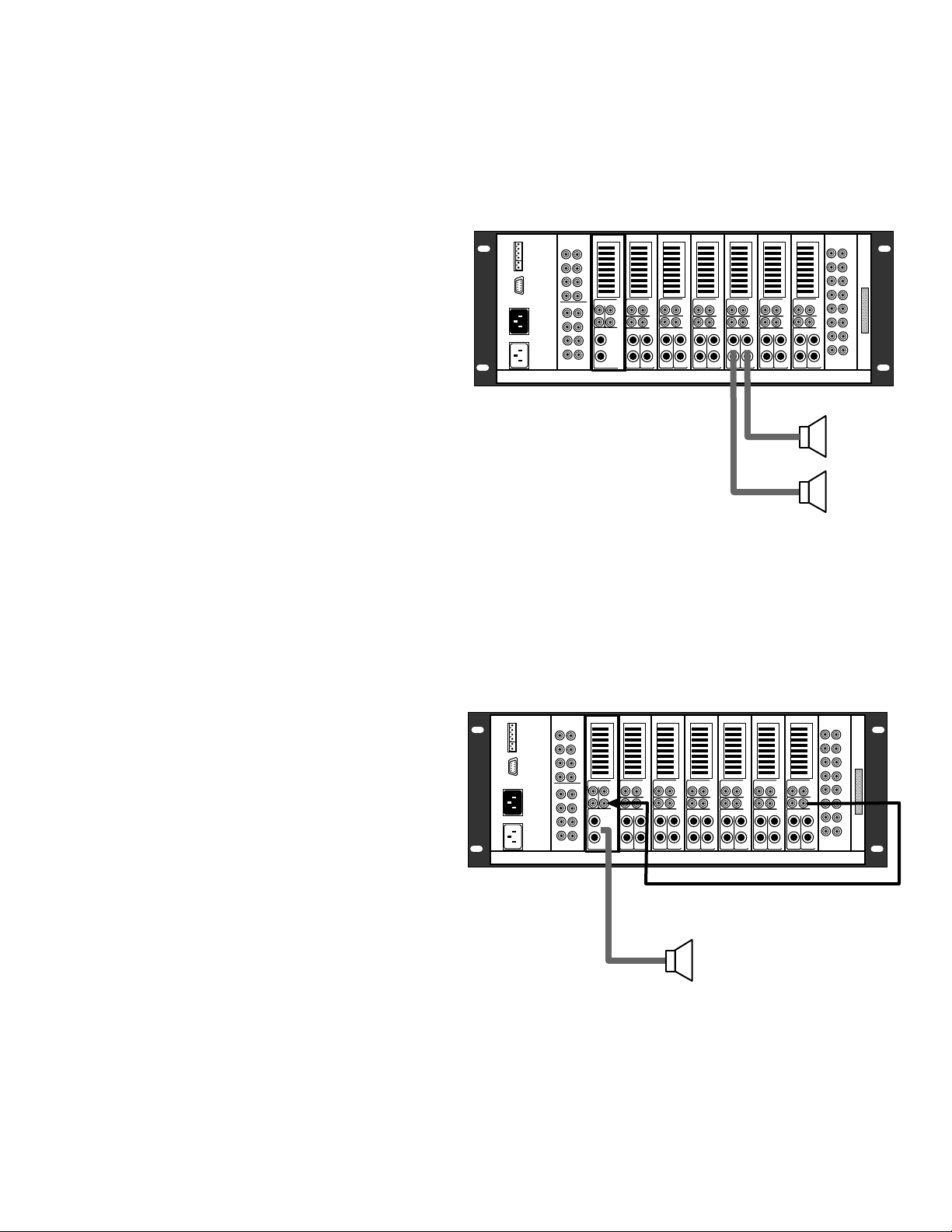
Composite Video Outputs (Only When Using The VSM-8 Video Switching Module)
The VSM-8 Video Switching
Module has a total of eight composite
video outputs marked 1 through 8.
Actually only seven outputs are used,
since the inclusion of the VSM-8 re-
moves one zone card. The outputs
numbered 1 through 7 correspond to
the first seven room buttons on the
front of the Delta-88 reading left to
right. Connect the composite video
cables to the Delta-88 corresponding to
the appropriate room. Please note that
the numbers on the VSM-8's output are
laid out differently than the AIB-50
Audio Input Board.
In this diagram, the composite video signal is being sent to both TVs in zones 1 & 2. For audio
distributionseveral optionsexistand heretwoare highlighted. Inzone one, thefixed line-level
audiosignal isalso beingsent tothe room'sTV such thatwhen acentral videosource isselected
on the room's keypad and the TV is set to an external input, the video source appears on screen.
The audio will both come out of the TV's speakers as well as the
room's speakers, with the TV's sound level controlled from the
TV's remote control and the room's sound controlled from the
keypad. In zone two, the TV will only receive the central video
sources video output when set to an external input. The audio
will only come out of the room's speakers using the keypad for
sound level control. Several other audio routing options exist
and are discussed in upcoming sections.
When using a single zones composite video output to drive more than one TV, make certain
to include one ISO-V Video Isolation Amplifier for every additional TV. When more than one
TV is fed a single composite video signal, a wavy interference may appear on both TVs. The
ISO-V allows for a clean split of a single composite video signal and will assist in eliminating
these wavy line forms. Furthermore, if you are running exceptionally long composite video
signals and experience a reduced level of video quality, the use of an ISO-V will improve and
enhance the video image.
AC Connections
The Delta-88 has two AC EIC connectors on its rear panel. The first is for
its own power and is plugged into the ACC-3000 or directly into an AC outlet.
The second is used as a switched outlet to power the PCT-8 (when used) or a
second Delta-88. Connection of the AC lines will be discussed in upcoming
sections.
FIX
VAR
SPEAKER
LR
+
-
LINE
RAM-50
1
2
3
4
5
6
7
8
AUDIO
INPUTS
FIX
VAR
SPEAKER
LR
+
-
LINE
RAM-50
FIX
VAR
SPEAKER
LR
+
-
LINE
RAM-50
FIX
VAR
SPEAKER
LR
+
-
LINE
RAM-50
FIX
VAR
SPEAKER
LR
+
-
LINE
RAM-50
FIX
VAR
SPEAKER
LR
+
-
LINE
RAM-50
4321 21
ADA BUS™
MUTE L.V.
ZONE L.V.
OUT
AC INPUT
AC
LOOP OUT
TO DELTA-88
12
12
3 4
34
5 6
56
78
78
VSM-8
VIDEO SWITCHER
V
I
D
E
O
I
N
P
U
T
V
I
D
E
O
O
U
T
P
U
T
LOOP
L
SUB
LR
+
-
R
BRIDGED
RBM-50
Zone 1
Zone 2
TV
TV
LOOP
O
O
OUTPUT
INPUT
ISO-V
12V AC
TRANS-
FORMER
HI-Z INPUT
Delta-88 Connections (cont.)
This manual suits for next models
32
Table of contents
Other A/DA Stereo System manuals


