A&D AD-8551R User manual

1WMPD4003931
AD-8551R
AD-8551
R
Modbus
RTU
Convertor
Modbus
R
TU
Convertor

This manual and Marks
All safety messages are identified by the following, “WARNING” or
“CAUTION”, of ANSI Z535.4 (American National Standard Institute: Product
Safety Signs and Labels). The meanings are as follows:
WARNING
A potentially hazardous situation which, if not avoided,
could result in death or serious injury.
CAUTION A potentially hazardous situation
which, if not avoided,
may result in minor or moderate injury.
This is a hazard alert mark.
This manual is subject to change without notice, at any time, to improve the
product.
The contents of the product specifications and this manual are subject to
change without any obligation on the part of the manufacturer.
Under the copyright laws, the software (program) described in this manual is
copyrighted, with all rights reserved.
The software may be installed into one computer and may not be installed
into other computers without the prior written consent of A&D Company,
Limited. Copying includes translation into another language, reproduction,
conversion, photocopy and offer or loan to another person.
2019 All rights reserved.
No part of this publication may be reproduced, transmitted, transcribed, or
translated into any language in any form by any means without the written
permission of A&D Company, Limited.

Contents
1. Introduction............................................................................................................................................................2
Features...........................................................................................................................................................2
Cautions...........................................................................................................................................................3
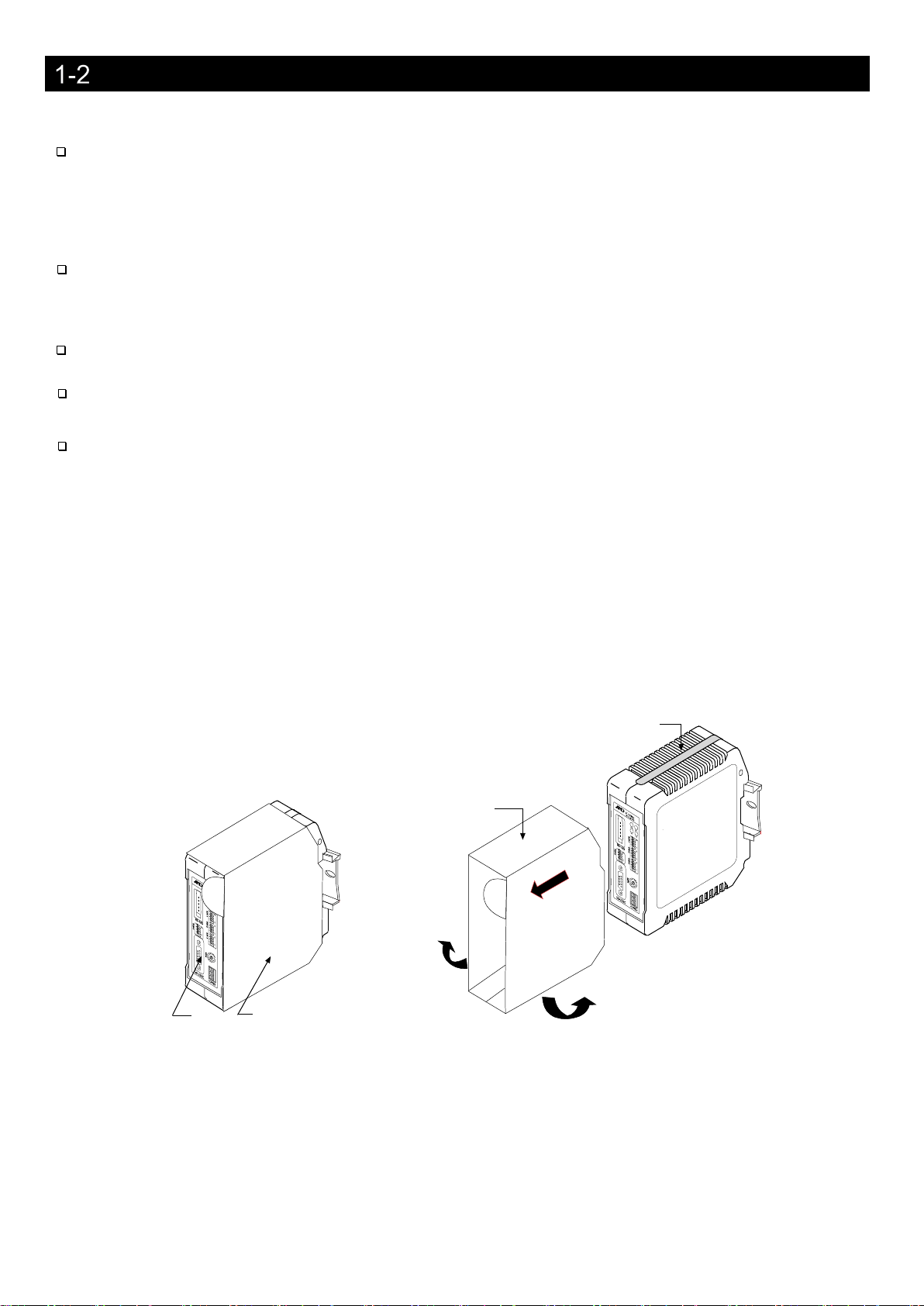
2. Composition and Names .......................................................................................................................................4
AD-8551R ........................................................................................................................................................4
Accessories......................................................................................................................................................4
3. Specifications ........................................................................................................................................................5
Dimensions ......................................................................................................................................................5
Applicable models............................................................................................................................................6
4. Power Terminal......................................................................................................................................................7
Power-supply voltage ......................................................................................................................................7
Connecting example........................................................................................................................................8
Internal connection status................................................................................................................................8
5. RS-485 Interface ...................................................................................................................................................9
RS-485 specifications......................................................................................................................................9
Connections...................................................................................................................................................10
6. RS-232C Interface...............................................................................................................................................11
RS-232C specifications .................................................................................................................................11
Connecting cable...........................................................................................................................................11
7. Switch ..................................................................................................................................................................12
How to operate the switch .............................................................................................................................12
Factory setting ...............................................................................................................................................12
RS-485 function settings ...............................................................................................................................13
RS-232C function settings.............................................................................................................................15
Fixed decimal point function..........................................................................................................................16
8. LED (status, error display)...................................................................................................................................17
9. Communicaiton in Modbus RTU Mode ...............................................................................................................18
Preparing for communication ........................................................................................................................19
Data address .................................................................................................................................................20
Detailed information on Holding Register 1...................................................................................................21
Detailed information on Holding Register 2 (only for AD-4212C/AD-4212D)..............................................................22
Communication format ..................................................................................................................................23
Operating example (When connected to the AD-4212C/AD-4212D) ...........................................................25
10. Communication in Command Mode..................................................................................................................27
Preparing for communication ......................................................................................................................27
Communication format ................................................................................................................................28
11. Troubleshooting .................................................................................................................................................29
Modbus RTU mode communication check..................................................................................................29
Command mode communication check ......................................................................................................30

2
1. Introduction
Thank you for purchasing the AD-8551R Modbus RTU convertor.
Please read this manual completely before using the AD-8551R.
Features
The AD-8551R converts the RS-232C communications of the weighing device into RS-485 (Modbus RTU)
communications (RS-232C/RS-485 converter). Use of the RS-485 enables the collection of data control of up to 31
weighing devices (addresses ranging from 1 to 63) by a single PLC.
■The RS-485 communication method of the AD-8551R can be used by selecting either Modbus RTU communication
(Modbus RTU mode) or ASCII code command communication (command mode).
■The measurement value can be reset to zero (re-zero) by operation from the PLC or PC.
■When connected to an AD-4212C and AD-4212D, etc., it is possible to change the response speed, perform
calibration with an external weight, and supply power from the weighing device.
■The hooks on the back of the AD-8551R allow one-touch mounting on a DIN rail.
RS-232C
communication
Weighing device
Weighing device
AD-8551R
Weighing device
RS-485
communication
Host
(PLC, PC, etc.)
AD-4212C, etc.
・ ・ ・
・ ・ ・
AD-8551R
AD-8551R
・ ・ ・
RS-232C
communication
RS-232C
communication

3
Cautions
Before use, confirm the following articles for safe operation.
Grounding The Convertor
Be sure to ground this convertor. (For the internal connection status of AD-8551R, refer to “4-3 Internal connection
status”.
Separate this earth ground line from others, like ground line of a motor, inverter or a power source. Unless the
convertor is grounded, it may result in receiving an electric shock, cause operation error or catch fire.
Proper Power Source And Power Cable
Confirm the AC voltage, frequency and power tolerance of the power cable (refer to “4. Power Terminal”). If the
voltage range of the cable is lower than the power line voltage, it may cause leakage or catching fire. Use pole
compression terminals to connect the power cable to the terminals.
Splashing Water
The module is not water-resistant type.
Flammable Gas
Do not install the convertor where flammable gas is present.
Heat Radiation Of The Module
Space out instruments to radiate heat sufficiently.
Do not use in an environment where the ambient temperature exceeds the operating temperature range [-10℃to
+50℃, 85% RH or less (no condensation)].
This unit is covered with a transparent plastic protective cover at the time of shipment.
After installing and connecting, be sure to remove the protective cover before turning on the power.
If it is used without removing the protective cover, this unit will overheat.
The protective cover is for preventing the entry of wire scraps and the like during installation and connecting.
Do not remove it until installation and connecting are complete.
This unit
Protective cover
This unit with a protective cover
Protective cover
This unit
①
②
Remove the two tabs on the lower
surface of the protective cover and
remove the protective cover.
How to remove the protective cover

4
2. Composition and Names
AD-8551R
Accessories
■Simplified instruction manual
■RS-485 connector (power clamp wire mount socket)
Model : AX-35505-6200-A (Made by 3M 35505-6200-A00 GF)
Front panel side
DIN rail mounting example
DIN rail groove
DIN rail (width 35mm)
Rear panel side
Pull down when removing
from DIN rail
DIN rail hook
Vent hole
Vent hole
DIN rail groove
RS-232C connector
DC power connector
RS-485 connector
LED (Status display part)
Switch

5
3. Specifications
Voltage requirement :12 to 24 VDC [+ 10%, -15%]
Power requirement:2W Max
Communication interface:RS-485 (Modbus RTU or command for connection to control equipment)
Refer to “5-1 RS-485 specifications”
:RS-232C interface (For connection to weighing device)
Refer to “6-1 RS-232C specifications”
Communication connector:5 pin (male):Made by 3M 35605-5153-A00 (For RS-485 interface)
D-Sub 9 pin (male) (For RS-232C interface)
Operating condition :-10℃to + 50℃, Max 85% RH (no condensation)
External dimensions:35 (W) x 110 (H) x 101 (D)
Mass :Approximately 170g
Accessory :RS-485 connector (power clamp wire mount socket) 1 piece
Dimensions
110
35.3 100
39.4
34.5
36.1
(3.5)
20°
1.3
28
5.5
Unit:mm

6
Applicable models
■Functions available for each model, accessories needed for connection to AD8551R.
Accessories needed to connect the AD8551R
to a weighing device Modbus RTU
Command
mode
⋆1
Convenient functions
Weighing device
output options
Cable needed for
connection between
weighing device and
AD8551R
Data that can be read from the host Operations that can be made from the host Power supply
from the
weighing
device
Auto power on
function⋆2
Weighing
value
Status
information
Response
speed Calibration status Calibration weight
value Re-zero Zero Taring Calibration with
internal weight
Calibration with your
own weight
Changing
the
display
digit
Changing the
response
speed
Changing
the unit
AD4212C Unnecessary Cable included with the
weighing device ○○○○○○× × × ○○○× ○⋆3 ○○
AD4212D
⋆6
Connector for
A&D’s external
display
Unnecessary Cable included with the
weighing device ○○○○○○× × ○○○○× ○○
Connector for the
PC/PLC
Unnecessary AX-KO4472-1000 ○× ○
AD4212A/B Unnecessary AX-KO1710-200 ○△⋆4 × × × ○× × × × ○× × ○× ○
GX-A Unnecessary AX-KO2466-200 ○△⋆4 × × × ○○○○× ○× ○○○○
GF-A Unnecessary AX-KO2466-200 ○△⋆4 × × × ○○○× × ○× ○○○○
FZi, HR-AZ Unnecessary AX-KO2466-200 ○△⋆4 × × × ○× × ○× ○× ○○○○
FXi, HR-A Unnecessary AX-KO2466-200 ○△⋆4 × × × ○× × × × ○× ○○○○
GX, GX-K, GP Unnecessary AX-KO1710-200 ○△⋆4 × × × ○× × ○× ○× ○○× ○
GF, GF-K, GP Unnecessary AX-KO1710-200 ○△⋆4 × × × ○× × × × ○× ○○× ○
BM, GH Unnecessary AX-KO2466-200 ○△⋆4 × × × ○× × ○× ○× ○○× ○
HR-i Unnecessary AX-KO2466-200 ○△⋆4 × × × ○× × × × ○× ○○× ○
GR Unnecessary AX-KO1710-200 ○△⋆4 × × × ○× × ○× × × ○○× ○
HR
HR-03
(Included with
weighing device)
AX-KO1710-200 ○△⋆4 × × × ○× × × × ○× ○○× ○
FC-i Unnecessary AX-KO2466-200 ○△⋆4 × × × × ××× × × × × ○× ×
HC-i HC-03i AX-KO1786-200 ○△⋆4 × × × × ○○× × × × × ○× ×
Eki, Ewi Unnecessary AX-KO2466-200 ○△⋆4 × × × ○× × × × × × ○○× ×
EJ, EJ-B EJ-03 AX-KO2466-200 ○△⋆4 × × × 〇× × × × × × ○○× ×
EK-L Unnecessary AX-KO2466-200 ○△⋆4 × × × 〇× × × × × × ○○△⋆5 ×
HV-CWP HVW-03CWP AX-KO3285-320 ○△⋆4 × × × × 〇〇× × × × ○○× 〇
HV-C, HV-CP,
HW-C, HW-CP HVW-03C AX-KO2466-200 ○△⋆4 × × × ×〇〇× × × × ○○× 〇
HV-G, HW-G,
HW-WP Unnecessary AX-KO1786-200 ○△⋆4 × × × ×〇〇× × × × ○○× ×
FG FG-23 / FG-24 AX-KO1786-200 ○△⋆4 × × × × 〇〇× × × × × ○× ×
FS-i FS-03i AX-KO3285-320 ○△⋆4 × × × ×〇〇× × × × ○○× ×
SC/SE SCE-03 AX-KO3285-320 ○△⋆4 × × × 〇× × × × × × × ○× ×
SW SW-03 AX-KO3285-320 ○△⋆4 × × × × 〇〇× × × × ○○× ×
⋆1.When transferring a large amount of data from a weighing device all at once (GLP output, batch output of data memory, etc.), data may be lost.
⋆2.If the weighing device does not have an auto power-on function or auto-start function, it is necessary to turn on the display or each weighing device by key operation after turning on the power.
⋆3.When using the AD4212C in command mode, it is necessary to change to internal settings in advance to enter key mode.
Also, control characters beginning with “@” output from the AD4212C are not output from the AD8551R to the RS-485 side.
⋆4.Some functions (calibration error flag) cannot be used.
⋆5.Power can be supplied from the weighing device when the adapter is connected to the weighing device.
⋆6.The AD4212D has two types of RS-232C connectors. When using in Modbus RTU mode, connect the connector for A&D’s external display, and when using in command mode, connect the connector for PC/PLC and RS-232C connector of the
AD8551R.

7
4. Power Terminal
When connected to the AD-4212C / AD-4212D, power can be supplied from the weighing instrument (RS-232C
connector). No power connecting is required (Refer to “6. RS-232C Interface”).
Power-supply voltage
Connect a constant voltage of external power supply (+ 10% -15%) within the range of 12 to 24 VDC to the DC power input
terminal.
●Do not use at a voltage exceeding the rated voltage range (12 to 24 VDC +10%-15%)
・Doing so may cause failure or heat generation.
・This unit may not operate normally.
●Ground the FG terminal of the switching power supply used for the power supply of this unit.
●The power line of this unit should be dedicated for this unit, and be separate from other drive devices.
・If strong noise is generated from the power line of another device, this unit may be damaged.
・This unit may not start normally due to the inrush current of other drive devices.
・Depending on the circuit configuration of this unit, other drive devices may not operate normally.
●Select a switching power supply capacity of approximately 2W per unit for the dedicated power supply line for this
unit.
・If the power capacity is insufficient, this unit may not operate normally.
■Connector:DC power input terminal
Signal name
Description
DC+
Power supply 12 to 24V input
0V
Power supply 0V input
FG
Frame ground
DC+
0V
FG
Caution

8
Connecting example
To insert or remove the wire, press the button part of the connector with a screwdriver or the like.
Modifying the tip of the wire with a bar-type crimp terminal or the like recommended.
Connection conductor specifications
Clamping range (rating)
0.20 mm
2
to 1.5 mm
2
Applicable wire
AWG
AWG24 to AWG16
Solder plated wire
0.2 mm
2
to 1.5 mm
2
Stranded wire
0.2 mm
2
to 1.5 mm
2
Bar crimp terminal
DIN 46228 Part 1
0.25 mm
2
to 1.5 mm
2
Bar crimp terminal
(With color)
DIN 46228 Part 4
0.25 mm
2
to 0.75 mm
2
Length
8 mm
Internal connection status
Power wire
Button part to push when inserting and
removing.
Bar crimp terminal
DC power input terminal
Approx. 820k
Ω
SLD(5)
Shell
FG(1)
0V(2)
RS-232C
RS-485
Din rail connection
Spring pin
AD-8551R

9
5. RS-485 Interface
RS-485 specifications
■Connector (Made by 3M 35605-5153-A00)
5
SLD
-
Shield
⋆1
4
-
-
N.C
3
SG
-
Signal ground
2
DATA-
Input/Output
Send / Receive data
1
DATA+
Input/Output
Send / Receive data
⋆1. Connect the shield of the RS-485 cable.
The shield terminal is connected to the DC power input terminal FG, RS-232C connector shell, and DIN rail
connection spring connector.
(Refer to “4-3 Internal connection status”)
■Communication specifications
Item Communication method [SW-2 No.3]
Modbus RTU mode Command mode
Baud rate
[
SW-1 No.1, 2
]
9600*, 19200, 38400, 115200bps
Data bit
8 bit (fixed)
Parity
[
SW-1 No.3, 4
]
EVEN*, ODD, NONE
Stop bit
1 bit (fixed)
Terminator
A silent interval of at
least 3.5 character
times
<CR><LF>
(
fixed
)
Terminating resister
[
SW-5 No.1
]
Built-in
:
Yes
(
100
Ω)
/ No * selected by switch
Device address setting
[
SW-3 No.3, 4, SW-4
]
01* to 63
Code
Modbus RTU*
ASCII code commands
*Factory setting
5
4
3
2
1

10
Connections
■How to connect
Single connection Multi drop connection
Item
Description
Accessory
①
RS-485 connector
(power clamp wire mount socket)
Model: AX-35505-6200-A
(Made by 3M 35505-6200-A00)
○
(
1 piece
)
②RS-485 cable
Recommended specification
・Twisted pair cable with shield
・Wire conductor size AWG#20(0.50mm2)
・
Characteristic impedance 100Ω
×
③Branching connector
Model: AX-35715-A (Made by 3M 35715-L010-A00)
*For multi drop connection.
RS-
485 connector (power clamp wire mount socket) also needs to
be purchased additionally.
×
■Connecting method of cable and connector
①Connect the two signal lines (DATA+, DATA-) in twisted pairs
and wire the shield of RS-485 to the SLD terminal.
If the host device does not have a signal ground, the SG terminal
connecting is not necessary.
②Insert the lead wire all the way in to the cover (yellow portion) without
peeling off the cover of the lead wire.
③
Push the cover into the body and fix it.
④Make sure that the cover is level with the body and that there is no gap
between the body and the cover.
②
RS-485 cable
①
RS-485 connector (power clamp wire mount socket)
③Branching connector
Cover (yellow part)
Before cable crimping
Body (black part)
After cable crimping

11
6. RS-232C Interface
RS-232C specifications
■Connector (D-Sub 9 pin, male)
⋆1.When connected to the AD-4212C / AD-4212, the AD-8551R can be operated by supplying power from the
weighing device.
■Communication specifications
Item
Setting
Baud rate [SW-1 No.1, 2]
2400*, 4800, 9600, 19200bps
Data bit
7 bit (fixed)
Parity
EVEN (fixed)
Stop bit
1 bit (fixed)
Terminator
<CR><LF> (fixed)
Code
ASCII
*Factory setting
Connecting cable
Connect with a cable applicable to the individual weighing device. Refer to “3-2. Applicable models”
■Connection diagram(When connected to a weighing device.)
⋆1.Depending on the weighing device, RXD and TXD may be shown on the opposite side (weighing device
output: TXD, weighing device input: RXD)
⋆2.May vary depending on the weighing device.
Pin No.
Signal
Direction
Description
1
(Vs)
Input
Input of power supply 0V ⋆1
2
RXD
Input
Received data
3
TXD
Output
Transmission data
4
-
-
N.C.
5
SG
-
Signal ground
6
-
-
N.C.
7
-
-
N.C.
8
-
-
N.C.
9
(Va)
Input
Input of power supply 12V
⋆1
Shell
-
-
Shield
Inch screw
1
2
3
4
5
6
7
8
9
Shell
Shield
Weighing
device(DCE)
RXD
⋆1
TXD
⋆1
SG
AD-8551R(DTE)
RXD
TXD
SG
FG
FG
2
3
5
(Vs)⋆2
1
(Vs)
(Va)⋆2
9
(Va)

12
7. Switch
・Set the parameters required for communication using the AD-8551R switches (SW-1 to 5).
Caution
・If the setting is changed, be sure to turn on the power off and on again of AD-8551R. When the power is turned on,
the switch status is read and applied to operations
How to operate the switch
SW-1 to 3, 5
When lever No.1 is moved to the “ON” side, “1” Is set.
SW-4
Turn the center arrow to set.
It can be set from 0 to F.
Factory setting
The switch status and settings at the factory setting are as follows. Refer to “7-3. RS-485 function settings” “7-4.
RS-232C function settings” for the settings that need to be changed.
SW-1 SW-2 SW-3 SW-4 SW-5
Item
Factory setting
value
Switch status at factory setting
RS-485 baud rate
9600
SW-1 No1
:
0
SW-1 No2
:
0
RS-485 parity
EVEN
SW-1 No3
:
0
SW-1 No4
:
0
RS-232C baud rate
2400
SW-2 No1
:
0
SW-2 No2
:
0
RS-485 communication method
Mosbus RTU mode
SW-2 No3
:
0
Device address
01
SW-3 No3
:
0
SW-3 No4
:
0
SW-4
:
1
Terminating resistor
None
SW-5 No1
:
0
Fixed decimal point function
AUTO
SW-5 No2
:
1
SW-5 No3
:
1
SW-5 No4
:
1
“1”
“0”
No. 1 on the left and No. 4 on the right.
Lever
1
1 1
0
0
0
0
0
0
0
0
1
0
0
0
0
0

13
RS-485 function settings
■Communication settings
SW-1
Baud rate : RS-485 Baud Rate Setting status Setting status Parity:RS-485 Parity
9600 bps
EVEN
19200 bps ODD
38400 bps Setting prohibited
115200 bps
NONE
■Settings for the RS-485 communication method
The RS-485 communication method of the AD-8551R can be selected from two types: communication using Modbus
RTU (Modbus RTU mode) and communication using ASCII code (command mode).
SW-2 No.3
RS-485 communication
method: Mode
Setting status
Modbus RTU mode
Command mode
“1”
“0”
SW-1
“1”
“0”
SW-2

14
■Device address allocation
Allocate a device address for each AD-8551R.
Device address allocation can be set from 01 to 63 using switches (SW-3, 4).
SW-2 No. 4, ADDRESS
Device Address
Setting status
SW-3
SW-4
Setting prohibited
0
01
1
02
2
03
3
04
4
05
5
06
6
07
7
08
8
09
9
10
A
11
B
12
C
13
D
14
E
15
F
16
0
17
1
18
2
19
3
20
4
21
5
22
6
23
7
24
8
25
9
26
A
27
B
28
C
29
D
30
E
31
F
32
0
33
1
34
2
35
3
36
4
37
5
38
6
39
7
40
8
41
9
42
A
43
B
44
C
45
D
46
E
47
F
48
0
49
1
50
2
51
3
52
4
53
5
54
6
55
7
56
8
57
9
58
A
59
B
60
C
61
D
62
E
63
F
SW-4
SW-3
“1”
“0”

15
■Terminating resistor selection
SW-5 No.1
Terminating Resistor Setting status
No terminating resistor
With terminating resistor (Between [DATA+] and
[DATA-] is 100Ω)
Example when several units are connected.
Single connection Multi drop connection
RS-232C function settings
■Communication setting
SW-2 No.1, No.2
Baud rate:RS-232C Baud Rate Setting state
2400bsp
4800bps
9600bps
19200bps
“1”
“0”
SW-5
“1”
“0”
SW-2
Connect termination resistors only at the ends of the network.
Weighing
device
Weighing
device
Weighing
device
Weighing
device
(ground)
(ground)

16
Fixed decimal point function
・The fixed decimal point function is valid only in Modbus RTU mode.
・If the connected weighing device has a smart range function, the number of digits after the decimal point is
automatically changed.
If you want to fix the number of digits, use the fixed decimal point function.
Example of storage format with fixed decimal point function
Weighing device
output value
Setting of decimal
point position
AD8551R internal data
Weighing value
(Holding Register:
40 2001 to 2002)
Decimal point
position
(Holding Register:
40 2005 to 2006)
123.456g
2
12345
2
3
123456
3
AUTO
⋆1
123456
3
123.45g
2
12345
2
3
123450
3
AUTO
⋆1
12345
2
SW-5 No. 2 to No. 4
⋆1.Depending on the output of the weighing device, the number of digits stored in the weighing value
(Holding Register: 40 2001 to 2002) and the decimal point position (Holding Register: 40 2005 to 2006) are
automatically switched.
Setting of decimal point position:
Decimal Point
Setting state
0
1
2
3
4
5
6
AUTO⋆1
“1”
“0”
SW-5

17
8. LED (status, error display)
■RUN Flashes status (Error display)
RUN illumination status
Status
Always illuminated
No communication error
Fast flashing(0.1 second period)
RS-485 communication error
Slow flashing
(
2 second period
)
RS-232C communication error
Caution
・Communication errors can be detected as framing errors, parity errors, and overrun errors.
・If an error is detected in both RS-485 and RS-232C, RUN illumination status is fast flashing.
(Prioritize RS-485 communication errors)
Place
Display
Color
Status
1 RUN Blue
Illuminates when the AD-8551R is powered on.
Flashes when the RS-485 or RS-
232C communication settings are
incorrect.
(Refer to the following “RUN illumination status (Error display”)
2
RXD
Yellow
Flashes when the AD-8551R receives data from the weighing device.
3
SD
Green
Flashes when the AD-8551R is transmitting data to the host.
4 RD Orange
Flashes when the AD-8551R is receiving data from the host (PLC, PC,
etc.)
1
2
3
4
Illumination timing at time of error
Illuminated
Off
Period
At the time of RS-485 communication error: 0.1 seconds
At the time of RS-232C communication error: 2 seconds

18
9. Communicaiton in Modbus RTU Mode
・Weighing value reading and zero reset (re-zero) are possible.
・When using the following models, calibration (sensitivity adjustment) is possible via Mdbus RTU.
When calibrating with a weighing device rather than the ones listed below, use the key, etc. of the weighing device
while looking at the display of the weighing device.
Applicable
model
Sensitivity
adjustment method
Outline of procedure
AD-4212C
External weight ⋆1
While monitoring the balance status with the Holding Register, it is
necessary to instruct data acquisition by Coil and to load and unload the
weight on the weighing instrument.
AD-4212D
External weight
⋆1
Built-in weight
After instruction by Coil, the holding register monitors until calibration is
completed.
⋆1.When changing the weight value to be used, refer to the instruction manual of the individual weighing device.
■Notes on Modbus RTU communication with AD-8551R.
・The function codes and maximum number that can be supported by AD-8551R are as follows.
Code
Function name
01
Read Coils
03
Read Holding Registers
05
Force Single Coil
15
Force Multiple Coils
⋆2
⋆2.This is possible only when the number of Coils to be rewritten is one.
Caution
Rewriting of Holding Register is not supported.
Table of contents
Other A&D Media Converter manuals