A&D AD-8552EIP User manual

1WMPD4004703
P
E
t
h
e
r
N
e
t
C
o
n
v
e
r
t
e
r
E
t
h
e
r
N
t
e
C
o
n
v
e
r
t
e
r
P
I
I
A
D
-
8
5
5
2
E
I
P
A
D
-
8
5
5
2
E
I
P
/
/

This manual and Marks
All safety messages are identified by the following, “WARNING” or
“CAUTION”, of ANSI Z535.4 (American National Standard Institute: Product
Safety Signs and Labels). The meanings are as follows:
WARNING
A potentially hazardous situation which, if not avoided,
could result in death or serious injury.
CAUTION
A potentially hazardous situation which, if not avoided,
may result in minor or moderate injury.
This is a hazard alert mark.
This manual is subject to change without notice, at any time, to improve the
product.
The contents of the product specifications and this manual are subject to
change without any obligation on the part of the manufacturer.
Under the copyright laws, the software (program) described in this manual is
copyrighted, with all rights reserved.
The software may be installed into one computer and may not be installed
into other computers without the prior written consent of A&D Company,
Limited. Copying includes translation into another language, reproduction,
conversion, photocopy and offer or loan to another person.
2022 All rights reserved.
No part of this publication may be reproduced, transmitted, transcribed, or
translated into any language in any form by any means without the written
permission of A&D Company, Limited.

3
Contents
1. Introduction.........................................................................................................................................................4
1-1 Features .......................................................................................................................................................4
1-2 Cautions .......................................................................................................................................................5
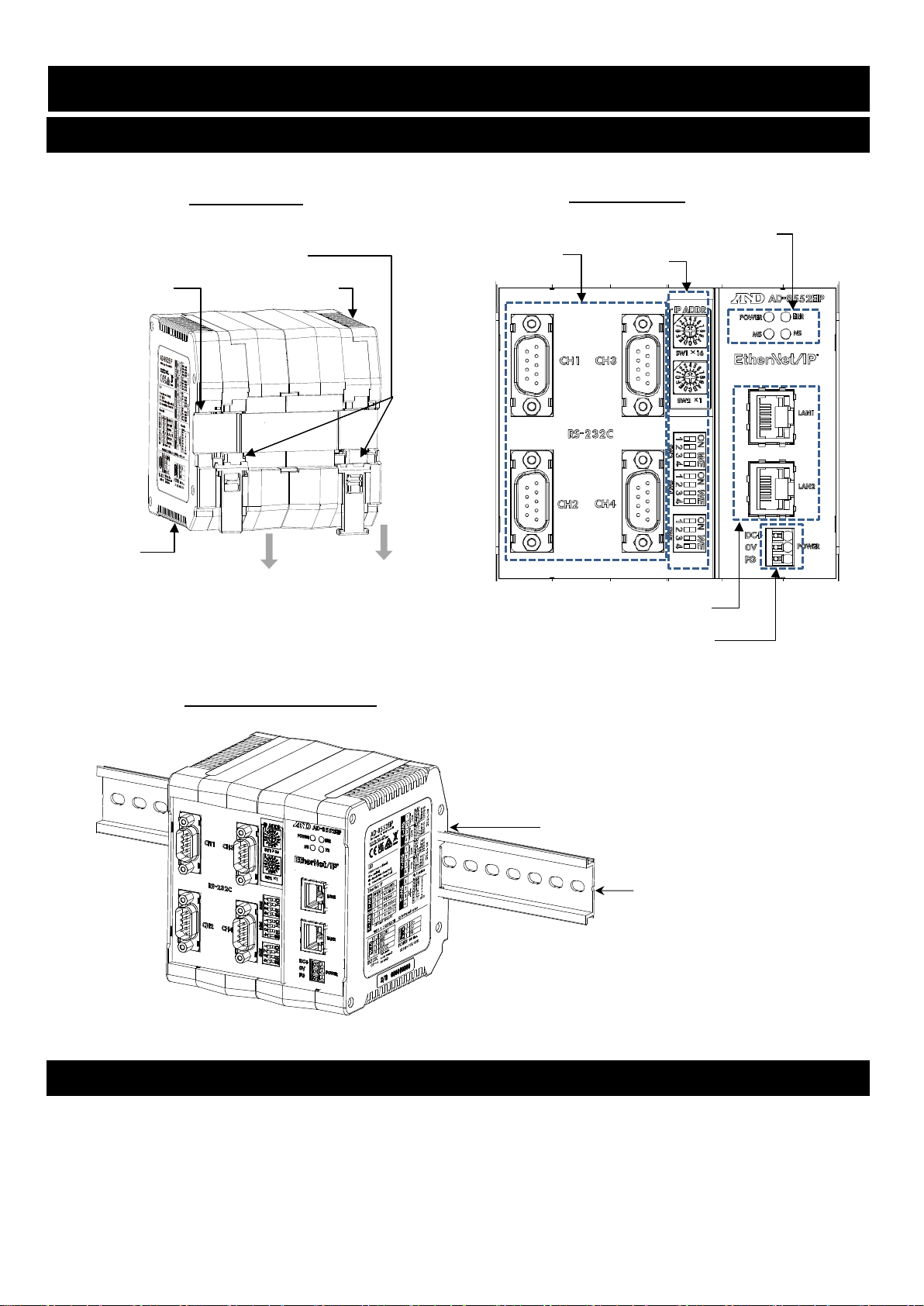
2. Composition and Names ....................................................................................................................................6
2-1 AD-8552EIP ..................................................................................................................................................6
2-2 Accessories ..................................................................................................................................................6
3. Specifications .....................................................................................................................................................7
3-1 Dimensions ...................................................................................................................................................7
3-2 Applicable models.........................................................................................................................................8
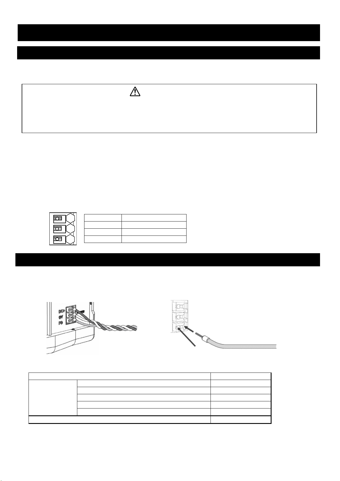
4. Power Terminal...................................................................................................................................................9
4-1 Power-supply voltage ...................................................................................................................................9
4-2 Connecting example .....................................................................................................................................9
5. EtherNet/IP Interface ........................................................................................................................................10
5-1 EtherNet/IP specifications...........................................................................................................................10
5-2 Connections................................................................................................................................................10
6. RS-232C Interface............................................................................................................................................11
6-1 RS-232C specifications ..............................................................................................................................11
6-2 Connecting cable ........................................................................................................................................11
7. Switch...............................................................................................................................................................12
7-1 How to operate the switch ..........................................................................................................................12
7-2 Factory setting ............................................................................................................................................12
7-3 EtherNet/IP switching settings ....................................................................................................................13
7-4 RS-232C function settings ..........................................................................................................................14
7-5 Fixed decimal point function .......................................................................................................................15
8. LED (status, error display) .............................................................................................................................16
9. Communication in EtherNet/IP .........................................................................................................................17
9-1 Preparing for communication ......................................................................................................................17
9-2 Output data (Instance150) ..........................................................................................................................18
9-3 Input data (Instance100).............................................................................................................................19
9-4 Detailed information of the Input data1 .......................................................................................................20
9-5 Detailed information of the Input data2(Only for AD-4212C/AD-4212D)..............................................21
9-6 Operating example(When connected to the AD-4212C/AD-4212D)......................................................22
10. WEB Interface ................................................................................................................................................25
10-1 Preparing for communication ....................................................................................................................25
10-2 HOME display...........................................................................................................................................25
10-3 Weighing Device Operation Screen..........................................................................................................26
10-4 Network Setting Screen ............................................................................................................................27
11. Troubleshooting ..............................................................................................................................................28

4
1.Introduction
Thank you for purchasing the AD-8552EIP EtherNet/IP converter.
Please read this manual completely before using the AD-8552EIP.
1-1 Features
The AD-8552EIP converts the RS-232C communications of the weighing device into EtherNet/IP.
■The measurement value can be reset to zero (re-zero) by operation from the host (PLC or PC).
■When connected to an AD-4212C and AD-4212D, etc., it is possible to change the response speed, perform calibration
with an external weight, and supply power from the weighing device.
■The hooks on the back of the AD-8552EIP allow one-touch mounting on a DIN rail.
RS-232C
communication
Weighing device
AD-8552EIP
EtherNet/IP
communication
Host
(PLC、PC, etc.)
AD-4212C, etc.
・ ・ ・
・ ・ ・
・ ・ ・
Weighing device
Weighing device
Weighing device
CH1
CH2
CH3
CH4
Weighing device
AD-8552EIP
Weighing device
Weighing device
Weighing device
CH1
CH2
CH3
CH4
Weighing device
AD-8552EIP
Weighing device
Weighing device
Weighing device
CH1
CH2
CH3
CH4

5
This unit with a protective cover
This unit
How to remove the protective cover
Protective cover
①
This unit Protective cover
1-2 Cautions
Before use, confirm the following articles for safe operation.
Grounding The Converter
Be sure to ground this converter.
Separate this earth ground line from others, like ground line of a motor, inverter or a power source. Unless the
converter is grounded, it may result in receiving an electric shock, cause operation error or catch fire.
Proper Power Source And Power Cable
Confirm the AC voltage, frequency and power tolerance of the power cable (refer to “4. Power Terminal”). If the
voltage range of the cable is lower than the power line voltage, it may cause leakage or catching fire. Use pole
compression terminals to connect the power cable to the terminals.
Splashing Water
The module is not water-resistant type.
Flammable Gas
Do not install the converter where flammable gas is present.
Heat Radiation Of The Module
Space out instruments to radiate heat sufficiently.
Do not use in an environment where the ambient temperature exceeds the operating temperature range [-10℃to
+50℃, 85% RH or less (no condensation)].
This unit is covered with a transparent plastic protective cover at the time of shipment.
After installing and connecting, be sure to remove the protective cover before turning on the power.
If it is used without removing the protective cover, this unit will overheat.
The protective cover is for preventing the entry of wire scraps and the like during installation and connecting.
Do not remove it until installation and connecting are complete.
②
Remove the two tabs on the lower
surface of the protective cover and
remove the protective cover.

6
2. Composition and Names
2-1 AD-8552EIP
2-2 Accessories
■Simplified instruction manual
Front panel side
DIN rail mounting example
DIN rail groove
DIN rail (width 35mm)
Rear panel side
DIN rail hook
DIN rail groove
RS-232C connector Switch
Pull down when removing from DIN rail
Vent hole
Vent hole
DC power connector
LED(Status display part)
EtherNet/IP connector

7
3. Specifications
Voltage requirement :24 VDC external power supply [+ 10%, -15%]
Power requirement:9W Max (When power is supplied to 4 units such as AD-4212C)
Communication interface :EtherNet/IP interface CT18 compliant (For connection with external devices)
Refer to “5-1 EtherNet/IP specifications”
:RS-232C interface (For connection to weighing device)
Refer to “6-1 RS-232C specifications”
Communication connector:RJ-45 modular connector (For EtherNet/IP interface)
D-Sub 9 pin (male) (For RS-232C interface)
Operating condition :0℃to + 50℃, Max 85% RH (no condensation)
External dimensions :105 (W) x 112 (H) x 103 (D) mm
Mass :Approximately 440g
3-1 Dimensions
Unit:mm

8
3-2 Applicable models
■Functions available for each model, accessories needed for connection to AD-8552EIP.
Accessories needed to connect the
AD8552EIP to a weighing device EtherNet/IP Convenient functions
Weighing device
output options
Cable needed for
connection between
weighing device and
AD8552EIP
Data that can be read from the host Operations that can be made from the host Power supply
to the
weighing
device
Auto power on
function⋆1
Weighing
value
Status
information
Response
speed Calibration status Calibration weight
value
Re-
zero Zero Taring Calibration with
internal weight
Calibration with your
own weight
Changing
the
display
digit
Changing the
response
speed
Changing
the unit
AD-4212C Unnecessary Cable included with the
weighing device ○ ○ ○ ○ ○ ○ × × × ○ ○ ○ × ○ ○
AD-
4212D
⋆2
Connector for
A&D’s external
display
Unnecessary Cable included with the
weighing device ○ ○ ○ ○ ○ ○ × × ○ ○ ○ ○ × ○ ○
⋆2
Connector for the
PLC
Unnecessary AX-KO4472-1000
AD-4212A/B Unnecessary AX-KO1710-200 ○ △※3 × × × ○ × × × × ○ × × × ○
BA-T Unnecessary AX-KO2741-180 ○ △※3 × × × ○ ○ ○ × × × × × ○ ○
BA Unnecessary AX-KO2741-180 ○ △※3 × × × ○ ○ ○ ○ × ○ × ○ ○ ○
GX-A、GX-M Unnecessary AX-KO2741-180 ○ △※3 × × × ○ ○ ○ ○ × ○ × ○ ○ ○
GF-A、GF-M Unnecessary AX-KO2741-180 ○ △※3 × × × ○ ○ ○ × × ○ × ○ ○ ○
FZi、HR-AZ Unnecessary AX-KO2741-180 ○ △※3 × × × ○ × × ○ × ○ × ○ ○ ○
FXi、HR-A Unnecessary AX-KO2741-180 ○ △※3 × × × ○ × × × × ○ × ○ ○ ○
GX、GX-K、GP Unnecessary AX-KO1710-200 ○ △※3 × × × ○ × × ○ × ○ × ○ × ○
GF、GF-K Unnecessary AX-KO1710-200 ○ △※3 × × × ○ × × × × ○ × ○ × ○
BM、GH Unnecessary AX-KO2741-180 ○ △※3 × × × ○ × × ○ × ○ × ○ × ○
HR-i Unnecessary AX-KO2741-180 ○ △※3 × × × ○ × × × × ○ × ○ × ○
GR Unnecessary AX-KO1710-200 ○ △※3 × × × ○ × × ○ × × × ○ × ○
FC-i Unnecessary AX-KO2741-180 ○ △※3 × × × × × × × × × × × × ×
HC-i HC-03i AX-KO1786-200 ○ △※3 × × × × ○ ○ × × × × × × ×
Eki、Ewi Unnecessary AX-KO2741-180 ○ △※3 × × × ○ × × × × × × ○ × ×
EJ、EJ-B EJ-03 AX-KO2741-180 ○ △※3 × × × 〇 × × × × × × ○ × ×
EK-L Unnecessary AX-KO2741-180 ○ △※3 × × × 〇 × × × × × × ○ ○ ×
HV-CWP HVW-03CWP AX-KO3285-320 ○ △※3 × × × × 〇 〇 × × × × ○ × 〇
HV-C、HV-CP、
HW-C、HW-CP HVW-03C AX-KO2741-180 ○ △※3 × × × × 〇 〇 × × × × ○ × 〇
HV-G、HW-G、
HW-WP Unnecessary AX-KO1786-200 ○ △※3 × × × × 〇 〇 × × × × ○ × ×
FG FG-23 / FG-24 AX-KO1786-200 ○ △※3 × × × × 〇 〇 × × × × × × ×
FS-i FS-03i AX-KO3285-320 ○ △※3 × × × × 〇 〇 × × × × ○ × ×
SC/SE SCE-03 AX-KO3285-320 ○ △※3 × × × 〇 × × × × × × × × ×
SW SW-03 AX-KO3285-320 ○ △※3 × × × × 〇 〇 × × × × ○ × ×
⋆1.If the weighing device does not have an auto power-on function or auto-start function, it is necessary to turn on the display or each weighing device by key operation after turning on the power.
⋆2.The AD4212D has two types of RS-232C connectors. Connect the display connector and the RS-232C connector of AD-8552EIP. (Do not use the PLC connector.)
⋆3.Some functions (calibration error flag) cannot be used.

9
4. Power Terminal
4-1 Power-supply voltage
Connect a constant voltage of external power supply (+ 10% -15%) within the range of 24 VDC to the DC power input terminal
of the AD-8552EIP.
●Do not use at a voltage exceeding the rated voltage range (24 VDC +10%-15%)
・Doing so may cause failure or heat generation.
・This unit may not operate normally.
●Ground the FG terminal of the switching power supply used for the power supply of this unit.
●The power line of this unit should be dedicated for this unit, and be separate from other drive devices.
・If strong noise is generated from the power line of another device, this unit may be damaged.
・This unit may not start normally due to the inrush current of other drive devices.
・Depending on the circuit configuration of this unit, other drive devices may not operate normally.
●Select a switching power supply capacity of approximately 9W per unit for the dedicated power supply line for this unit.
・If the power capacity is insufficient, this unit may not operate normally.
■Connector:DC power input terminal
Signal name
Description
DC+
Power supply 24V input
0V
Power supply 0V input
FG
Functional Ground
4-2 Connecting example
To insert or remove the wire, press the button part of the connector with a screwdriver or the like.
Modifying the tip of the wire with a bar-type crimp terminal or the like recommended.
Connection conductor specifications
Clamping range (rating)
0.20 mm
2
to 1.5 mm
2
Applicable wire
AWG
AWG24 to AWG16
Solder plated wire
0.2 mm
2
to 1.5mm
2
Stranded wire
0.2 mm
2
to 1.5mm
2
Bar crimp terminal
DIN46228 Part1
0.25 mm
2
to 1.5mm
2
Bar crimp terminal
(With color)
DIN46228 Part4
0.25 mm
2
to 0.75 mm
2
Length
8mm
DC+
0V
FG
Power wire
Button part to push when inserting
and removing.
Bar crimp terminal
Caution

10
5. EtherNet/IP Interface
5-1 EtherNet/IP specifications
■Connector(RJ-45 modular connector)
⋆1.AD-8552EIP is compatible with Auto MDI-X / MDI. The LAN cable can be used either straight or cross.
■Communication specifications
5-2 Connections
⋆1.LAN cable is not included. Please use a commercially available product.
Pin No.
MDI
⋆1
MDI-X
⋆1
1
TD+
RD+
2
TD-
RD-
3
RD+
TD+
4
-
-
5
-
-
6
RD-
TD-
7
-
-
8
-
-
Housing
Communication standard
EtherNet/IP (CT18 compliant)
Vender ID
188
:
A&D Company Limited
Device type
43 (0x2B)
:
Generic Device
Communication function
Cyclic communication (Implicit message)
Message communication (Explicit message)
IP address setting method
DIP switch, WEB interface
Transmission speed
10/100Mbps ( Autonegotiation)
Communication method
Full duplex / half duplex ( Autonegotiation)
Connection form
Star connection, daisy chain connection
Connection cable
Shielded twisted pair cable (STP)
Straight / Cross, category 5e and above
8 1
RD:Receive data(Input)
TD:Send data(Output)
LAN cable
(Shielded twisted pair cable (STP cable),
Straight / cross, CAT5e and above)
・Connect to PLC, HUB, PC, etc.
LAN1
LAN2
POWER
DC+
0V
FG

11
6. RS-232C Interface
6-1 RS-232C specifications
■Connector (D-Sub9 pin, male)
⋆1.When connected to specific weighing device such as AD-4212C / AD-4212D, Weighing device can be
operated by supplying power from the AD-8552 EIP.(Refer to “3-2 Applicable models”)
■Communication specifications
Item Setting
Baud rate [SW-3, 4 No.1 to 4] 2400*, 9600, 19200, 38400bps
Data bit 7 bit (fixed)
Parity EVEN (fixed)
Stop bit 1 bit (fixed)
Terminator <CR><LF> (fixed)
Code ASCII
*Factory setting
6-2 Connecting cable
Connect with a cable applicable to the individual weighing device. Refer to “3-2. Applicable models”.
■Connection diagram(When connected to a weighing device.)
*1. Depending on the weighing device, RXD and TXD may be shown on the opposite side (weighing device
output: RXD, weighing device input: TXD)
*2.May vary depending on the weighing device.
Pin No.
Signal Direction
Description
1 (Vs) Output Output of power supply 0V ⋆1
2 RXD
Input Input data
3 TXD Output Output data
4 - - N.C.
5 SG - Signal ground
6 - - N.C.
7 - - N.C.
8 - - N.C.
9 (Va) Output Output of power supply 12V ⋆1
Shell - - Shield
Inch screw#4-40UNC
1
2
3
4
5
6
7
8
9
Shell
Shield
W
eighing
device
(DCE)
T
XD
*
1
R
XD
*
1
SG
AD-8552EIP(DTE)
RXD
TXD
SG
FG
FG
2
3
5
(Vs) *2
1
(Vs)
(Va) *2
9
(Va)

12
7. Switch
・Set the parameters required for communication using the AD-8552EIP switches (SW-1 to 5).
Caution
・If the setting is changed, be sure to turn on the power off and on again of AD-8552EIP.
When the power is turned on, the switch status is read and applied to operations.
7-1 How to operate the switch
SW-1, 2
Turn the center arrow to set.
It can be set from 0 to F.
SW-3 to 5
When lever No.1 is moved to the “ON” side, “1” Is set.
7-2 Factory setting
The switch status and settings at the factory setting are as follows. Refer to “7-3. EtherNet/IP switching settings”
“7-4. RS-232C function settings” for the settings that need to be changed.
SW-1 SW-2 SW-3 SW-4 SW-5
Item
Factory setting
value
Switch status at factory setting
IP address (4th octet)
2
SW-1
:
0
SW-2
:
2
RS-232C(CH1) baud rate
2400
SW-3 No1
:
0
SW-3 No2
:
0
RS-232C(CH2) baud rate
2400
SW-3 No3
:
0
SW-3 No4
:
0
RS-232C(CH3) baud rate
2400
SW-4 No1
:
0
SW-4 No2
:
0
RS-232C(CH4) baud rate
2400
SW-4 No3
:
0
SW-4 No4
:
0
No Function
SW-5 No1
:
0
Fixed decimal point function
AUTO
SW-5 No2
:
1
SW-5 No3
:
1
SW-5 No4
:
1
1
11
00 0 00000
0
“1”
“0”
No.1 to No.4
Lever
2
0

13
7-3 EtherNet/IP switching settings
■IP address setting
The IP address allocation can be set within the following range by using the switch (SW-1, 2).
[ 192.168.0.1 ] to [ 192.168.0.254 ], [ 192.168.1.10 ]
(To set an IP address other than the above, refer to "10-4 Network setting screen".)
<Setting example>
IP ADDR
Caution
・Please consult with your network administrator before connecting to a network.
・Set the IP address so that it does not overlap with other devices.
SW-1
SW-2
IP address
0 0
Becomes the address set on WEB interface, “10-4.
Network setting screen”.
0
1
[ 192.168.0.1 ]
0
2
[ 192.168.0.2 ]
n1
n2
[ 192.168.0. ( n1×16 + n2×1 ) ]
F
E
[ 192.168.0.254 ]
F
F
[ 192.168.1.10 ]
When set as shown on the left
SW-1 : 2 → n1 = 2
SW-2 : 4 → n2 = 4
4th octet = n1×16 + n2 ×1
= 2 ×16 + 4 ×1
= 32 + 4
= 36
IP address = [ 192.168.0.36 ]
SW2 ×1
SW1 ×16

14
7-4 RS-232C function settings
■Communication setting
SW-3
CH1: RS-232C Baud Rate Setting state Setting state CH2: RS-232C Baud rate
2400 bps
2400 bps
9600 bps 9600 bps
19200 bps
19200 bps
38400 bps
38400 bps
SW-4
CH3: RS-232C Baud Rate Setting state Setting state CH4: RS-232C Baud Rate
2400 bps
2400 bps
9600 bps 9600 bps
19200 bps
19200 bps
38400 bps
38400 bps
“1”
“0”
SW-3
No.1, 2 No.3, 4
“1”
“0”
SW-4
No.1, 2No.3, 4

15
7-5 Fixed decimal point function
・The digits (decimal point position) of the weight value data of EtherNet/IP can be fixed.
・If the connected weighing device has a smart range function, the number of digits after the decimal point is
automatically changed.
If you want to fix the number of digits, use the fixed decimal point function.
Example of storage format with fixed decimal point function(Example of CH1)
Weighing device
output value
(CH1)
Setting of decimal
point position
AD-8552EIP internal data
Weighing value
Instance100:byte 0 to 3
[ CH1 Weighing value ]
Decimal point position
Instance100:byte 6 to 7
[ CH1 Decimal point position ]
123.456g
2
12345
2
3
123456
3
AUTO
※1
123456
3
123.45g
2
12345
2
3
123450
3
AUTO
※1
12345
2
SW-5 No.2 to No.4
⋆1 Depending on the output of the weighing device, the number of digits stored in the weighing value
(Instance100:byte 0 to 3, 18 to 21, 36 to 39, 54 to 57) and the decimal point position (lnstance100:byte 6 to 7, 24
to 25, 42 to 43, 60 to 61) are automatically switched.
Setting of decimal point position:
Decimal Point
Setting sate
0
1
2
3
4
5
6
AUTO※1
“1”
“0”
SW-5

16
8. LED (status, error display)
Display
Function
Color
Status
POWER
Power on
Green lit
The AD-8552EIP is powered on.
ERR
Error
Red lit
There is something wrong with the AD-8552EIP.
MS Module Status
Off
The AD-8552EIP is not powered on.
Green lit
It is working normally.
Green blink
Not initialized.
Red lit
An unrecoverable failure has occurred.
Red blink
A recoverable failure has occurred.
NS Network Status
Off
The AD-8552EIP is not powered on.
Green lit
The EtherNet/IP connection is established.
Green blink
The EtherNet/IP connection is not established.
Red blink
One or more connections have timed out.
POWER ◯◯ERR
MS ◯◯NS

17
9. Communication in EtherNet/IP
・When an EtherNet/IP connection is established between the AD-8552EIP and the PLC, data is periodically
communicated by cyclic data. Cyclic data consists of "9-2 Output data" and "9-3 Input data".
・Weighing values can be read and zero reset (rezero) is possible.
・If you are using the following models, you can calibrate (Sensitivity adjustment) via EtherNet/IP.
When calibrating with a weighing device other than the following models, operate with the keys of the weighing device
while looking at the display of the measuring instrument.
Applicable
model
Sensitivity
adjustment
method
Outline of procedure
AD-4212C
External
weight
⋆1
While monitoring the balance status with the Input data(Instance100), it is
necessary to instruct data acquisition by Output data(Instance150) and to
load and unload the weight on the weighing instrument.
AD-4212D
External
weight
⋆1
Built-in
weight
After instruction by Output data(Instance150), the Input data (Instance100)
monitors until calibration is completed.
⋆1.When changing the weight value to be used, refer to the instruction manual of the individual weighing device.
9-1 Preparing for communication
1. Set the following setting items so that the RS-232C of the weighing instrument and AD-8552EIP are the same.
Reference: AD-4212C/AD-4212D factory setting
Setting item
Weighing device
AD-8552EIP
Baud rate
2400*, 9600, 19200, 38400 bps
Data bit
7 bit*
Parity
EVEN*
Stop bit
1 bit*
Terminator
<CR><LF>*
Data output format
A&D standard format*
―
Data output mode
Settings for continuous
output of weighing values.
(
stream mode*
)
―
*AD-8552EIP factory setting(normally, the factory setting of AD-4212C / AD-4212D is the same.)
2. Set the following setting items so that the host (PLC, PC, etc.) and AD-8552EIP are the same.
<Setting example>
Setting item
Host
(
PLC, PC, etc.
)
AD-8552EIP
IP address*
[192.168.0.1]
[192.168.0.2]
*Make sure that IP addresses do not overlap in the connected network.
3. Refer to ”4-2 Connecting example”, “5-2 Connections”, “6-2 Connecting cable” for connecting.
・Normally, when using the AD-4212C/AD-4212D, power can be supplied from the RS-232C terminal, so connecting
to the power terminal of the AD-4212C/AD-4212D is not required.
・When connecting to the AD-4212D, connect to the AD-8552EIP using the AD-4212D display connector.
4. Turn on the device power.

18
9-2 Output data (Instance150)
The data transferred from PLC etc. to the AD-8552EIP is called Output data.
Output data is used when outputting a command to the measuring instrument.
■Output data layout (O->T) [ PLC etc. -> AD8552EIP -> Weighing device(CH1 to 4) ]
Assembly
Instance Attribute Byte Name Data type Contents
150 3
0,1
CH1 Command
UInt16
Command output
(
Weighing device CH1
)
2,3
CH2 Command
UInt16
Command output
(
Weighing device CH2
)
4,5
CH3 Command
UInt16
Command output
(
Weighing device CH3
)
6,7
CH4 Command
UInt16
Command output
(
Weighing device CH4
)
■Details of the Output data
・Command output [CH1~4 Command] (CH1:byte 0,1、CH2:byte 2,3、CH3: byte 4,5、CH4: byte 6,7)
The following command is output to the weighing device connected to CH1-4.
※1.The AD-8552EIP outputs each command to the connected instrument when a "1" is written.
※2.The operation differs depending on the weighing device. For individual operation commands, refer to "3-2
Applicable model" or the instruction manual of the relevant weighing device.
Bit
Contents
※1
Remarks
0
“EXC” command output
Used for calibration (sensitivity
adjustment)
1
“CAL” command output
2
“PRT” command output
3 “R” command output
Performing zero reset (rezero) of the
weighing device
4
“SMP” command output
Change the readability of the weighing
device
5 “U” command output ※2Change response characteristics or
switch units
6
“RZ” command output
Performing zero reset (rezero) of the
weighing device
7
“Z” command output
8
“T” command output
Performing tare
9-15
No function

19
9-3 Input data (Instance100)
The data transferred from AD-8552EIP to PLC, etc. is called Input data.
Input data is used when acquiring data from the weighing device.
■Input data layout (T->O) [ Weighing device (CH1 to 4) -> AD8552EIP -> PLC, etc. ]
Assembly
Instance Attribute Byte Name Data type Contents
100 3
0
~
3
CH1 Weighing value
Int32
Weighing value
Weighing
device
CH1
4,5
CH1 Status information
UInt16
Status information
※
1
6,7
CH1 Decimal point position
UInt16
Decimal point
position
8,9
CH1 Weighing unit
UInt16
Weighing unit
10,11
CH1 Response characteristics
UInt16
Response
characteristics
12,13
CH1 Adjustment status
UInt16
Adjustment status
14
~
17
CH1 Adjustment weight value
Int32
Adjustment weight
value
※2
18
~
21
CH2 Weighing value
Int32
Weighing value
Weighing
device
CH2
22,23
CH2 Status information
UInt16
Status information
※1
24,25
CH2 Decimal point position
UInt16
Decimal point
position
26,27
CH2 Weighing unit
UInt16
Weighing unit
28,29
CH2 Response characteristics
UInt16
Response
characteristics
30,31
CH2 Adjustment status
UInt16
Adjustment status
32
~
35
CH2 Adjustment weight value
Int32
Adjustment weight
value
※2
36
~
39
CH3 Weighing value
Int32
Weighing value
Weighing
device
CH3
40,41
CH3 Status information
UInt16
Status information
※
1
42,43
CH3 Decimal point position
UInt16
Decimal point
position
44,45
CH3 Weighing unit
UInt16
weighing unit
46,47
CH3 Response characteristics
UInt16
Response
characteristics
48,49
CH3 Adjustment status
UInt16
Adjustment status
50
~
53
CH3 Adjustment weight value
Int32
Adjustment weight
value
※2
54
~
57
CH4 Weighing value
Int32
Weighing value
Weighing
device
CH4
58,59
CH4 Status information
UInt16
Status information
※1
60,61
CH4 Decimal point position
UInt16
Decimal point
position
62,63
CH4 Weighing unit
UInt16
Weighing unit
64,65
CH4 Response characteristics
UInt16
Response
characteristics
66,67
CH4 Adjustment status
UInt16
Adjustment status
68
~
71
CH4 Adjustment weight value
Int32
Adjustment weight
value
※2
※1.If you connect to anything other than the AD-4212C / D, the functions will be limited.
※2.This function can be used only when connected to the AD-4212C / D.

20
9-4 Detailed information of the Input data1
■Weighing value [CH1 to 4 Weighing value] (CH1:byte 0 to 3, CH2:byte 18 to 21, CH3:byte 36 to 39、CH4:byte 54 to 57),
Decimal point position [CH1 to 4 Decimal point position] (CH1: byte 6,7 CH2: byte 24,25, CH3: byte 42,43, CH4: byte 60,61)
Example of weighing value and decimal point value by output of Weighing device (CH1)(When the decimal point
position setting by SW-5 is AUTO)
Weighing value
of the weighing
device (CH1)
Byte Name Contents Data Remarks
123.456g
0 to 3
CH1 Weighing value
Weighing value
0x0001E240
⇒
123456
6,7
CH1 Decimal point position
Decimal point
position
0x0003 ⇒
3
123.456g
0 to 3
CH1 Weighing value
Weighing value
0x00003039
⇒
12345
6,7
CH1 Decimal point position
Decimal point
position
0x0002 ⇒
2
■Status information of the weighing device [CH1 to 4 Status information] (CH1:byte 4,5, CH2:byte 22,23, CH3:byte 40,41,
CH4:byte 58,59)
Byte
Status
Remarks
0
Stable / unstable status of weighing
value
0
:
Unstable
1
:
Stable
1 Weighing range over flag 1:When the weighing value exceeds the maximum display
2 Non-weighing status flag
0
:
When receiving the current weighing value from the weighing device
1:When weighing value is interrupted for 2 seconds or more, and rezero
or calibration is in progress.
3
Rezeroing flag
1
:
Rezero processing in progress
※1
4
No function
5
Adjustment in progress flag
1
:
Adjustment in progress
※1
6 Adjustment error flag※2
1
:
When calibrating If the value of the weighing calibration weight is not
appropriate.
(
This flag returns to 0 when shifting to the weighing mode.
)
7 No function
8 to 15
※1.The flag does not change when operated with the keys of the weighing device.
※2.This flag can be used only when connected to the AD-4212C / D.
Caution: Be sure to read "Weighing value" and "Weighing value status information" at the same time. If they
are read separately, the correspondence between the "weighing value" and the "weighing value
status information" may differ depending on the update timing, so the weighing value status cannot
be determined accurately.
■Weighing unit [CH1~4 Weighing unit] (CH1:byte 8,9, CH2:byte 26,27, CH3:byte 44,45, CH4:byte 62,63)
Relationship between value and unit
Value
Unit (mode)
Value
Unit (mode)
Value
Unit (mode)
0x0000 g (gram) 0x0006
Mom (Momme)
0x000C
TL (Tael)
0x0001 mg (milligram) 0x0007
OZ (Ounce)
0x000D
Tol (Tola)
0x0002 kg (kilogram) 0x0008
Lb (Pound)
0x000E
MES (Messghal)
0x0003 PCS (pieces) 0x0009
OZt (Troy Ounce)
0x000F
N (Newton)
0x0004 % (percent) 0x000A
dwt (pennyuweight)
0x0010
MLT (Programmable unit)
0x0005 ct (carat) 0x000B
GN (Grain)
0xFFFF
Indistinguishable
Table of contents
Other A&D Media Converter manuals
Popular Media Converter manuals by other brands

rako
rako RAVIR Installation, Programming and Operating Instructions

Dolby Laboratories
Dolby Laboratories SEU4 manual

DEVA Broadcast
DEVA Broadcast SmartGen Mini Maintenance and operation instruction manual

CYP
CYP VHC-1 Operation manual

GRASS VALLEY
GRASS VALLEY ADVC-110 Converting instructions

Snell Advanced Media
Snell Advanced Media KudosPro MC500 Operator's manual