Abit KR7A-133R User manual

Copyright and Warranty Notice
The information in this document is subject to change without notice and does not
represent a commitment on part of the vendor, who assumes no liability or responsibility
for any errors that may appear in this manual.
No warranty or representation, either expressed or implied, is made with respect to the
quality, accuracy or fitness for any particular part of this document. In no event shall the
manufacturer be liable for direct, indirect, special, incidental or consequential damages
arising from any defect or error in this manual or product.
Product names appearing in this manual are for identification purpose only and
trademarks and product names or brand names appearing in this document are the
property of their respective owners.
This document contains materials protected under International Copyright Laws. All
rights reserved. No part of this manual may be reproduced, transmitted or transcribed
without the expressed written permission of the manufacturer and authors of this manual.
If you do not properly set the motherboard settings, causing the motherboard to
malfunction or fail, we cannot guarantee any responsibility.


4200-0266-02 Rev. 1.01
KR7A-133/KR7A-133R Motherboard User’s Manual
Index
CHAPTER 1. INTRODUCTION OF KR7A-133/KR7A-133R FEATURES
................................................................................................. 1-1
1-1. FEATURES OF KR7A-133/KR7A-133R MOTHERBOARD.......................................1-1
1-2. SPECIFICATIONS....................................................................................................1-2
1-3. ITEM CHECKLIST ..................................................................................................1-4
1-4. LAYOUT DIAGRAM FOR KR7A-133/KR7A-133R.................................................1-5
CHAPTER 2. INSTALLING THE MOTHERBOARD.............................. 2-1
2-1. INSTALLATION OF THE AMD ATHLON™XP, ATHLON™AND DURON™CPU .........2-2
2-2. INSTALLING THE MOTHERBOARD TO THE CHASSIS ................................................2-5
2-3. INSTALLING SYSTEM MEMORY .............................................................................2-6
2-4. CONNECTORS, HEADERS AND SWITCHES...............................................................2-8
CHAPTER 3. INTRODUCING THE BIOS ................................................ 3-1
3-1. CPU SETUP [SOFT MENU™III].........................................................................3-3
3-2. STANDARD CMOS FEATURES SETUP MENU .........................................................3-6
3-3. ADVANCED BIOS FEATURES SETUP MENU...........................................................3-9
3-4. ADVANCED CHIPSET FEATURES SETUP MENU .....................................................3-13
3-5. INTEGRATED PERIPHERALS ................................................................................. 3-20
3-6. POWER MANAGEMENT SETUP MENU ..................................................................3-24
3-7. PNP/PCI CONFIGURATIONS SETUP MENU ...........................................................3-31
3-8. PC HEALTH STATUS ...........................................................................................3-34
3-9. LOAD FAIL-SAFE DEFAULTS ...............................................................................3-35
3-10. LOAD OPTIMIZED DEFAULTS ..............................................................................3-35
3-11. SET PASSWORD...................................................................................................3-36
3-12. SAVE & EXIT SETUP ...........................................................................................3-36
3-13. EXIT WITHOUT SAVING ......................................................................................3-36
CHAPTER 4. RAID SETTING GUIDE ...................................................... 4-1
4-1. THE FEATURES OF RAID ON THE KR7A-133R .....................................................4-1
4-2. RAID SETUP ON THE KR7A-133R.....................................................................4-1
4-3. THE BIOS SETTING MENU ...................................................................................4-2
CHAPTER 5. HPT 372 DRIVER INSTALLATION .................................. 5-1
5-1. DOS®...................................................................................................................5-1
5-2. WINDOWS®98 SE ................................................................................................5-1
5-3. WINDOWS®2000..................................................................................................5-3
CHAPTER 6. HPT 372 RAID ADMINISTRATOR INSTALLATION
GUIDE .................................................................................... 6-1
APPENDIX A. VIA 4 IN 1 DRIVERS INSTALLATION FOR WINDOWS®98
SE & WINDOWS®2000 ........................................................ A-1

KR7A-133/KR7A-133R
APPENDIX B. INSTALLING THE HARDWARE MONITOR SYSTEM ... B-2
APPENDIX C. BIOS UPDATE GUIDE ........................................................ C-2
APPENDIX D. TROUBLESHOOTING (NEED ASSISTANCE?) ............... D-2
APPENDIX E. HOW TO GET TECHNICAL SUPPORT............................. E-2

Introduction of KR7A-133/KR7A-133R Features
User’s Manual
1-1
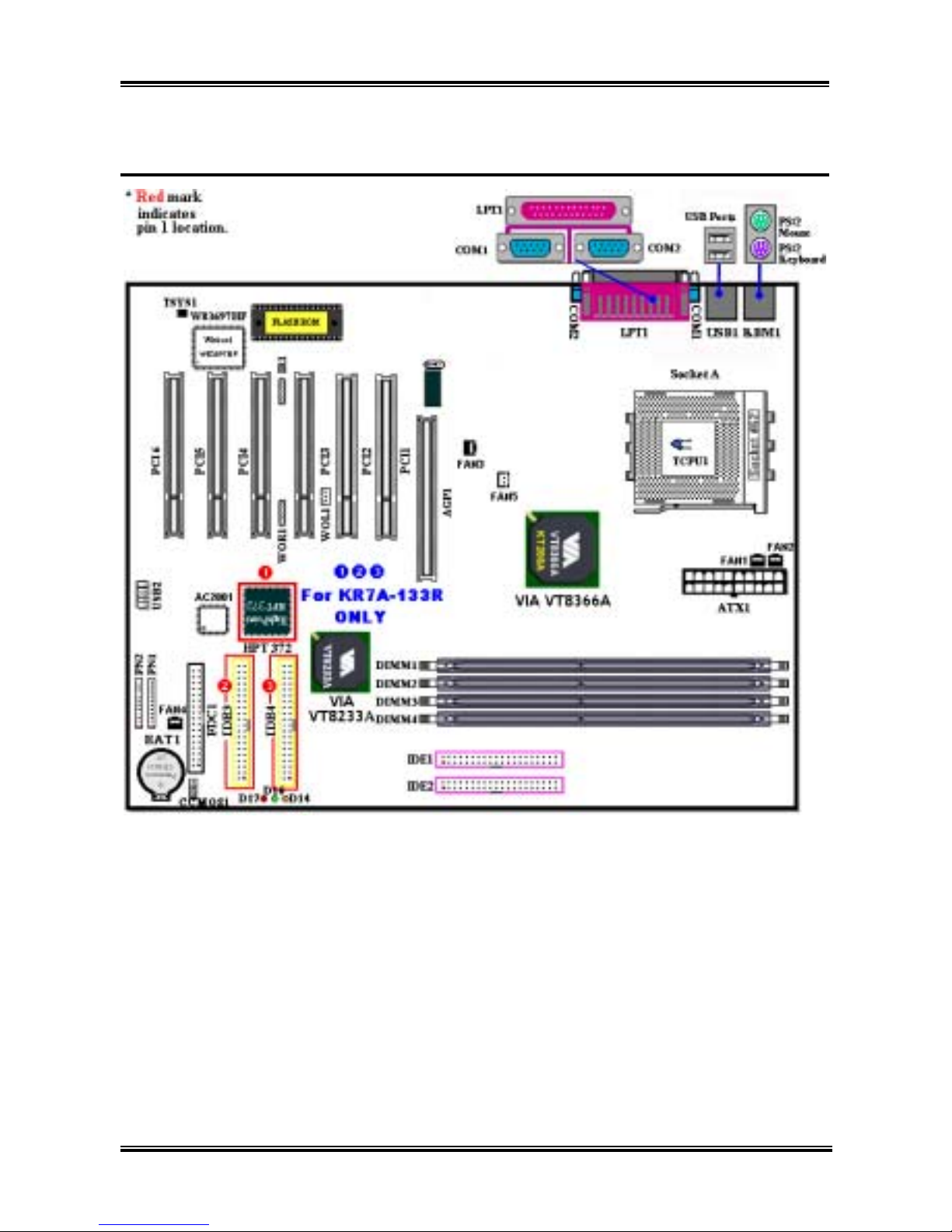
Chapter 1. Introduction of KR7A-133/KR7A-133R
Features
1-1. Features of KR7A-133/KR7A-133R Motherboard
This motherboard is designed for AMD Socket A Athlon™XP, Athlon™and Duron™processors. It
supports the AMD Socket-A structure, with up to 3 GB (Unbuffered) or 3.5 GB (Registered) of memory,
super I/O, and Green PC functions.
The KR7A-133/KR7A-133R uses the VIA VT8366A and VT8233A chipsets to make the evolutionary
move from PC 100/PC 133 SDRAM to PC 1600/PC 2100 DDR SDRAM, increasing the speed of the
system and memory buses from 100 MHz to 133 MHz. Its 200/266 MHz memory interface supports the
wide range of PC 1600/PC 2100 DDR SDRAM memory devices now on the market.
VIA VT8366A is a system bus controller, or northbridge, that houses the high-speed system elements
critical to overall system performance while also containing the system interface to the processor. The
key functions of the VT8366A System Controller include the 266 MHz Athlon System Bus, the 266 MHz
DDR Memory Subsystem, the AGP 4X/2X/1X modes Graphics Interface (AGP 2.0 Compliant) and the
33 MHz/32-bit PCI Bus Interface (PCI 2.2 Compliant), including arbiter.
DDR SDRAM is the newest memory standard, it provides the maximum translation bandwith and also
greatly improves data transaction delays. This feature improves whole system performance and speed,
especially multimedia environment applications.
The KR7A-133/KR7A-133R has a built in Ultra DMA 133 function. This means that it provides speedier
HDD throughput boosting overall system performance. Ultra DMA 133 is the newest standard for IDE
devices. It enhances existing Ultra DMA 33 technology by increasing both performance and data integrity.
This new high-speed interface almost double the Ultra DMA 66 burst data transfer rate to 133 Mbytes/sec.
The result is maximum disc performance using the current PCI local bus environment. Another benefit is
you can connect four IDE devices in your system through either Ultra DMA 66, Ultra DMA 100 or Ultra
DMA 133. You will have more flexibility to expand your computer system.
KR7A-133R’s built-in HighPoint HPT 372 chipset gives you the capability to support Ultra DMA 133.
Ultra DMA 133 is the newest standard for IDE devices. It provides two IDE channels (IDE3, IDE4) that
also support Ultra DMA 133 specifications, and it allows for four additional IDE devices in your
computer system. It can give you high performance and efficiency data transfer rate through the IDE
channels. This also means that your computer, in total, can connect up to eight IDE devices (IDE1 ~
IDE4). This allows for maximum expandability for future hardware demands. This chipset also supports
IDE RAID, inlcuding RAID 0, RAID 1 and RAID 0+1. This feature enables you to maximize your data
storage performance and security. (KR7A-133R Only)
KR7A-133/KR7A-133R provides high flexibility to users building AMD Socket A Athlon™XP, Athlon™
and Duron™systems. It provides the option of 133MHz/133MHz CPU and memory bus combinations.
The KR7A-133/KR7A-133R has built-in hardware monitoring functions (refer to Appendix B for detailed
information) to ensure a safe computing environment.

Chapter 1
KR7A-133/KR7A-133R
1-2
1-2. Specifications
1. CPU
! Supports AMD Athlon™ XP 1500+ ~ 2100+ or future Socket A processors based on 200 MHz/266
MHz (100 MHz/133 MHz Double Data Rate)
! Supports AMD Athlon™ 700 MHz ~ 1.4 GHz or future Socket A processors based on 200 MHz/266
MHz (100 MHz/133 MHz Double Data Rate)
! Supports AMD Duron™ 600 MHz ~ 1.2 GHz or future Socket A processors based on 200 MHz (100
MHz Double Data Rate)
! Supports 200 MHz Alpha EV6 bus for the AMD Athlon™XP, Athlon™and Duron™processors
2. Chipset:
#VIA VT8366A and VT8233A chipsets
! Supports Ultra DMA 33, Ultra DMA 66, Ultra DMA 100 and Ultra DMA 133 IDE protocol
! Supports Advanced Configuration and Power Management Interface (ACPI)
! Accelerated Graphics Port connector supports AGP 2X (3.3V) and 4X (1.5V) mode
(Sideband) device
! Supports 200 MHz/266 MHz (100 MHz/133 MHz Double Data Rate) memory bus settings
#Ultra DMA 133/RAID (For KR7A-133R Only)
! HighPoint HPT 372 IDE controller
! Supports Ultra DMA 133 MB/sec data transfer rate
! Supports RAID0 (Stripping mode for boosting performance) mode
! Supports RAID1 (Mirroring mode for data security) mode
! Supports RAID 0+1 (Stripping and Mirroring) mode
3. Memory (System Memory)
! Four 184-pin DIMM slots support PC1600/PC2100 DDR SDRAM modules
! Supports four DIMMs of unbuffered DDR SDRAM for a maximum of 3 GB (64, 128, 256, 512
and 1024 MB DDR SDRAM modules)
! Supports four DIMMs of registered DDR SDRAM for a maximum of 3.5 GB (64, 128, 256, 512
and 1024 MB DDR SDRAM modules)
4. System BIOS
! SOFT MENU™ III technology, can easily set the processor parameters
! Award Plug and Play BIOS supports APM and DMI
! Write-Protect Anti-Virus function by AWARD BIOS
5. Multi I/O Functions
! Two channels of Bus Master IDE ports supporting up to four Ultra DMA 33/66/100/133 devices
(KR7A-133 Only). And two channels (IDE3 & IDE4) of Bus Master IDE ports supporting up to
four Ultra DMA 33/66/100/133 specifications HDD devices (KR7A-133R Only)
! One PS/2 keyboard and PS/2 mouse connectors
! One floppy port connector (up to 2.88MB)
! One parallel port connector (Standard/EPP/ECP)
! Two serial ports connectors
! Two USB connectors
! One USB header for two extra USB channels

Introduction of KR7A-133/KR7A-133R Features
User’s Manual
1-3
6. Miscellaneous
! ATX form factor
! One AGP slot, six PCI slots
! Built-in Wake on LAN header
! Built-in IrDA TX/RX header
! Built-in Wake On Ring header
! Hardware monitoring:Included fan speed, voltages, CPU and system environment temperature
! Board size: 305 * 245mm
$ Supports Wake On LAN, Modem, but your ATX power supply 5V standby power must be
able to provide at least a 720mA current capacity. Otherwise, the functions may not work
normally.
$ PCI slot 5 shares IRQ signals with the HPT 372 IDE controller (supports Ultra DMA 133). The
driver for HPT 372 IDE controller supports IRQ sharing with other PCI devices. But if you
install a PCI card that doesn’t allow IRQ sharing with other devices into PCI slot 5, you may
encounter some problems. Furthermore, if your Operating System doesn’t allow peripheral
devices to share IRQ signals with each other, such as Windows®NT for example, you can’t
install a PCI card into PCI slot 5. (KR7A-133R Only)
$ HPT 372 IDE controller is designed to support high-speed and high performance mass storage
devices. Thus we suggest that you don’t connect non-disk devices that use ATA/ATAPI
interfaces, such as CD-ROM to HPT 372 IDE connector (IDE3 & IDE4). (KR7A-133R Only)
$ This motherboard supports the standard bus speeds of 66MHz/100MHz/133MHz that are used
by specific PCI, processor and chipset specifications. Exceeding these standard bus speeds is
not guaranteed due to the specific component specifications.
$ Specifications and information contained in this manual are subject to change without notice.
Note
All brand names and trademarks are the property of their respective owners.

Chapter 1
KR7A-133/KR7A-133R
1-4
1-3. Item Checklist
Check that your package is complete. If you discover any damaged or missing items, please contact your
retailer or dealer.
%One ABIT KR7A-133 or one KR7A-133R motherboard
%One 80-wire/40-pin ribbon cable for master and slave Ultra DMA 133, Ultra DMA 100, Ultra DMA
66 or Ultra DMA 33 IDE devices (KR7A-133 Only)
%Two 80-wire/40-pin ribbon cable for master and slave Ultra DMA 133, Ultra DMA 100, Ultra DMA
66 or Ultra DMA 33 IDE devices (KR7A-133R Only)
%One ribbon cable for 3.5” floppy disk devices
%One compact disc for support drivers and utilities
%One USB cable
%One DIY bag
%One user’s manual for the motherboard
%One quick installation guide for the motherboard
%One floppy disk of HPT 372 drivers (KR7A-133R Only)

Introduction of KR7A-133/KR7A-133R Features
User’s Manual
1-5
1-4. Layout Diagram for KR7A-133/KR7A-133R
Figure 1-1. KR7A-133/KR7A-133R motherboard component location

Chapter 1
KR7A-133/KR7A-133R
1-6

Installing the Motherboard
User’s Manual
2-1
Chapter 2. Installing the Motherboard
This KR7A-133/KR7A-133R motherboard not only provides all standard equipment for classic personal
computers, but also provides great flexibility for meeting future upgrade demands. This chapter will
introduce step by step all of the standard equipment and will also present, as completely as possible,
future upgrade capabilities. This motherboard is able to supports all AMD Socket A Athlon™XP,
Athlon™and Duron™processors now on the market. (For details, see specifications in Chapter 1.)
This chapter is organized according the following features:
1. Installation of the AMD Socket A Athlon™XP, Athlon™and Duron™CPU
2. Installing the Motherboard to the Chassis
3. Installing System Memory
4. Connectors, Headers and Switches
&&&& Before Proceeding with the Installation &&&&
Before you install or unplug any connectors or add-on cards, please remember to turn the ATX power
supply switch off (fully turn the +5V standby power off), or take the power cord off. Otherwise, you may
cause the motherboard components or add-on cards to malfunction or be damaged.
'
User Friendly Instructions
Please read our instructions carefully and follow them step-by-step. Our objective is to enable the novice
computer user to perform the installation by himself. We have attempted to write this document in a very
clear, concise and descriptive manner to help overcome any obstacles you may face during installation.
Diagram and Photos
This chapter contains many color drawings, diagrams and photos, we strongly recommend you read this
chapter use the PDF file that is stored on the CD-Title. Color improves the clarity and quality of the
diagrams. For the downloadable edition, as files larger than 3 MB are difficult to download, we will cut
the graphics and photo resolution to reduce the manual file size. In such this case, if your manual is
downloaded from our WEB site and not from a CD-ROM, enlarging graphics or photos will distort the
image.

Chapter 2
KR7A-133/KR7A-133R
2-2
2-1. Installation of the AMD Athlon™XP, Athlon™and Duron™
CPU
Note
!Installing a heatsink and cooling fan is necessary for heat to dissipate from your processor. Failing
to install these items may result in overheating and processor damage.
!The AMD Socket A processor will produce a lot of heat while operating, so you need to use a large
heat sink that is especially designed for the AMD socket A processor. Otherwise, it may result in
overheating and processor damage.
!If your processor fan and its power cable are not installed properly, never plug the ATX power
cable into the motherboard. This can prevent possible processor damage.
!Please refer to your processor installation manual or other documentation with your processor for
detailed installation instructions.
The AMD Socket A Athlon™XP, Athlon™and Duron™processor installation is easy, like Socket 7
Pentium®processors before. Because it uses the “Socket A” ZIF (Zero Insertion Force) socket, you can
easily fix the processor firmly into position. Figure 2-1 shows you what the socket A looks like, and how
to open the lever. The socket A has more pins than the socket 7. Therefore, a Pentium®level processor
cannot be inserted into a socket A.
When you raise the lever, you have to loosen the socket lock. Please raise the lever to the end, and
prepare to insert the processor. Next, you need to align the processor pin 1 to the socket pin 1. If you put
it in the wrong direction, you will not be able to insert the processor easily, and processor pins will not
fully go into the socket. If this is the case, please change the direction, until it easily and fully inserts into
the socket A. See Figure 2-2. At the same time check the processor temperature detection thermistor
height (if your motherboard has this component), then you can slowly insert the processor into the Scoket
A. Finally, you need to check that the processor edge and the Socket A edge is parallel. It should be
parallel and not tilted.
When you finish the above, push the lever down to its original position, you should feel the lever lock the
socket A. You have then finished the processor installation.

Installing the Motherboard
User’s Manual
2-3
Heatsink Installation Hints
Because the processor will produce a lot of heat while operating, we suggest you use a heatsink approved
by AMD to be safe and to keep the processor temperature within normal operation temperatures. The
heatsink will be large and heavy, so the fixing plate has a strong tension. When you install the heatsink on
to the processor and its socket, you have to very carefully fix the fixing plate to the processor socket hook
on both sides. If you do not pay attention to this, you may make the fixing plate scratch the PCB surface
and cause circuit damage, break socket hooks or damage the die on the top of processor.
Please follow the sequence metioned below, Do Not
inverse the sequence. Otherwise, you may have a
situation like the photo on the left. Because of the
design of the CPU socket, the left side hooks are not
as strong as the right side hooks. If you follow our
suggestions you will prevent your processor and
socket from damage.
Note
Considering the chassis structure problem, please
always take off the motherboard from chassis,
before adding or removing a heatsink kit.
The proper procedure to install the heatsink kit:
First, install the processor into the processor socket.
Insert the heatsink left side fix plate into the
processor socket left side fix hooks. Make sure the fit
is very tight. Check the photo on the left.

Chapter 2
KR7A-133/KR7A-133R
2-4
Insert a flat screwdriver into the middle slot of the
right side fix plate and push down. Then you can
push the fix plate over the socket hooks on the right
side. Check the photo on the left.
Check the photo on the left. You have finished the
heatsink installation.
Now hold the whole heatsink and slightly shake it,
make sure the buttom right side of the heaksink does
not contact the right side of the Socket (see bottom
picture). Otherwise, the processor die does not have
proper contact with the heatsink. This situation may
cause processor damage.
Remember to install the heatsink fan power cable to
the CPU fan header on the motherboard.
Now you can reinstall the motherboard back into the
chassis.
When all above procedures done, you can connect
the ATX power cable to the motherboard.
If you have different types of heatsink kit, please
refer to the manual that came with the heatsink kit.
The left photo shows another type of heatsink fix
plate design. The install sequences are still the same,
from right side to left side. Just remember that.
We strongly recommand you to buy a heatsink
with three holes in the fix plate. This will provide
the best stabability and won’t cause the Socket fix
hooks to be broken or damaged.
The left photo shows the bottom right side of the
heaksink in contact with the right side of the Socket.
In this situation, the processor die does not properly
contact the heatsink. If you start the computer at this
monent, it will immediately cause the processor
damage. Always check this place when you finish the
heatsink installation.

Installing the Motherboard
User’s Manual
2-5
2-2. Installing the Motherboard to the Chassis
After you install the processor to the motherboard, you can start to fix the motherboard into the chassis.
Most computer chassis will have a base on which there will be many mounting holes that allows the
motherboard to be securely attached and at the same time, prevents short circuits. There are two ways to
attach the motherboard to the base of chassis:
!With studs
!With spacers
Please refer to figure 2-3, which shows the studs and spacers. There may be several types, but all look
like the figures below:
In principle, the best way to attach the
motherboard is with studs. Only if you
are unable to do this should you attach the
board with spacers. Take a careful look at
the motherboard and you will see many
mounting holes on it. Line these holes up
with the mounting holes on the base. If
the holes line up and there are screw
holes this means you can attach the
motherboard with studs. If the holes line
up and there are only slots, this means
you can only attach the motherboard with
spacers. Take the tip of the spacers and
insert them into the slots. After doing this
to all the slots, you can slide the
motherboard into position aligned with
the slots. After the motherboard has been
positioned, check to make sure everything
is OK before putting the casing back on.
Figure 2-4 shows you the way to affix the
motherboard using studs or spacers.
Note
If the motherboard has mounting holes, but they don’t line up with the holes on the base and there are
no slots to attach the spacers, don’t worry, you can still attach the spacers to the mounting holes. Just
cut the bottom portion of spacers (the spacer they may be a little hard to cut, so be careful with your
hands). In this way you can still attach the motherboard to the base without worrying about short
circuits. Sometimes you may need to use the plastic springs to isolate the screw from the motherboard
PCB surface, because the circuit wire may be near by the hole. Be careful, don’t let the screw contact
any the printed circuit wire or parts on the PCB that are near the fixing hole, otherwise it may damage
the board or cause board malfunctioning.

Chapter 2
KR7A-133/KR7A-133R
2-6
2-3. Installing System Memory
This motherboard provides four 184-pin DDR DIMM sites for memory expansion. The DDR DIMM
sockets support 8 M x 64 (64 MB), 16 Mx 64 (128 MB), 32M x 64 (256 MB), 64 M x 64 (512 MB), and
128 M x 64 (1024 MB) or double density DDR DIMM modules. Minimum memory is 64 MB and the
maximum memory is 3 GB (Unbuffered) or 3.5 GB (Registered) DDR SDRAM. There are four memory
module sockets on the system board (for a total of eight banks). In order to create a memory array,
following rules must be followed.
!For those modules, we suggest that you be populate DIMM1 to DIMM4 in order.
!Supports single and double density DDR DIMMS.
Table 2-1. Valid Memory Configurations
Bank Memory Module Total Memory
Bank 0, 1
(DDR DIMM1)
64 MB, 128 MB, 256 MB,
512 MB, 1024 MB
64 MB ~ 1 GB
Bank 2, 3
(DDR DIMM2)
64 MB, 128 MB, 256 MB,
512 MB, 1024 MB
64 MB ~ 1 GB
Bank 4, 5
(DDR DIMM3)
64 MB, 128 MB, 256 MB,
512 MB, 1024 MB
64 MB ~ 1 GB
Bank 6, 7
(DDR DIMM4)
64 MB, 128 MB, 256 MB,
512 MB, 1024 MB
64 MB ~ 1 GB
Total System Memory for Unbuffered DDR DIMM 64 MB ~ 3 GB
Total System Memory for Registered DDR DIMM 64 MB ~ 3.5 GB
Generally, installing DDR SDRAM modules to your
motherboard is an easy thing to do. You can refer to
Figure 2-5 to see what a 184-pin PC1600 & PC2100
DDR SDRAM module looks like.
Unlike installing SIMMs, DIMMs may be
“snapped” directly into the socket. Note: Certain
DDR DIMM sockets have minor physical differences.
If your module doesn't seem to fit, please do not force it into the socket as you may damaged your
memory module or DDR DIMM socket.
The following procedure will show you how to install a DDR DIMM module into a DDR DIMM socket.
Step 1. Before you install the memory module, please place the computer power switch in the off
position and disconnect the AC power cord from your computer.
Step 2. Remove the computer’s chassis cover.
Step 3. Before touching any electronic components, make sure you first touch an unpainted, grounded
metal object to discharge any static electricity stored on your clothing or body.
Step 4. Locate your computer’s 184-pin memory expansion DDR DIMM socket.

Installing the Motherboard
User’s Manual
2-7
Step 5. Insert the DDR DIMM module into the expansion
socket as shown in the illustration. Note how the
module is keyed to the socket. You can refer to
Figure 2-6 for the details. This insures the DDR
DIMM module will be plugged into the socket in
one way only. Firmly press the DDR DIMM
module into DDR DIMM socket, making certain
the module is completely seated in the DDR
DIMM socket.
Step 6. Once the DDR DIMM module has been installed,
the installation is complete and the computer’s
cover can be replaced. Or you can continue to
install other devices and add-on cards that are
mentioned in the following section.
Note
When you install a DDR DIMM module fully into the DDR DIMM socket, the eject tab should be
locked into the DDR DIMM module very firmly and fit into its indention on the both sides.
It is difficult to differentiate between the PC1600 and PC2100 DDR SDRAM modules from the exterior.
The only way you can identify them is to look at the sticker on the DDR SDRAM module. The sticker
will tell you which kind of structure module the DDR SDRAM is.
Frequency Asked Question About DDR DIMM Memory
Does the KR7A-133/KR7A-133R motherboard support ECC memory?
Yes, the KR7A-133/KR7A-133R does support ECC memory modules.
It supports up to 3 GB of non-registered memory, or 4 GB of registered memory. The maximum DDR
memory support of KR7A-133/KR7A-133R is 3.5 GB rather than 4 GB. This limitation is caused by the
PC architecture. The missing 0.5 G memory address is reserved for PCI I/O space, AGP aperture mapping
space and other onboard device I/O space, so although the KT266A datasheet states that the memory
support is up to 4 GB, the system only uses about 3.5 GB with four 1 GB DDR memory installed. In
another words, BIOS and operating system will only report 3.5 GB.
Why does the power on process take longer time for KR7A-133/KR7A-133R system? Is there any
memory compatibility issue? (KR7A-133/KR7A-133R and other KT266A chipset board)
While KR7A-133/KR7A-133R system is powered on, the BIOS will do a memory checking process and
it takes about 5 ~ 15 seconds, then continue POST sequence.
According to the datasheet of VIA KT266A chipset (Revision 2.1, September 14, 2001), x 4 bit memory
chip is not supported.
Page 3, Advanced High-Performance SDR/DDR DRAM Controller
Supports 8 banks up to 4 GB DRAMs (512Mb x 8/x 16 DRAM technology) for registered SDR/DDR
modules
Supports 6 banks up to 3 GB DRAMs (512Mb x 8/x 16 DRAM technology) for unbuffered SDR/DDR
modules

Chapter 2
KR7A-133/KR7A-133R
2-8
Most of the DDR memory 1GB modules available
now consist of 64 M x 4 chip, which can't be used on
KR7A-133/KR7A-133R motherboard. Before
purchasing the memory module, we suggest users
carefully check out the memory specification, which
should be provided by memory module vendor. The
left picture illustrates a DDR 1 GB module made by
64 M x 4 chip and special technology- stacking two
memory chips together. This kind of memory can't be
supported by VIA KT266A chipset.
2-4. Connectors, Headers and Switches
Inside the case of any computer several cables and plugs have to be connected. These cables and plugs are
usually connected one-by-one to connectors located on the motherboard. You need to carefully pay
attention to any connection orientation the cables may have and, if any, notice the position of the first pin
of the connector. In the explanations that follow, we will describe the significance of the first pin.
We will show you all of the connectors, headers and switches here, and tell you how to connect them.
Please pay attention and read the entire section for necessary information before attempting to finish all of
the hardware installation inside the computer chassis.
Figure 2-7 shows you all of the connectors and headers that we’ll discuss in the next section, you can use
this diagram to visually locate each connector and header we describe.
Note
This components diagram will be slightly different because there are a number of models. We’ll use
the KR7A-133R motherboard as standard; all descriptions of connector and header will be based on
the KR7A-133R motherboard.
All connectors, headers and switches mentioned here, will depend on your system configuration. Some
features you may (or may not) have and need to connect or configure depending on the peripheral. If your
system doesn't have such add-on cards or switches you can ignore some special feature connectors.

Installing the Motherboard
User’s Manual
2-9
Figure 2-7. All connectors and headers for the KR7A-133R
First, Let’s see the headers that KR7A-133R uses, and what their functions are. We will show you all the
connectors and headers.
(1). ATX1: ATX Power Input Connector
Attach the connector from the power supply to the
ATX1 connector here. Remember you have to push
the connector from the ATX power supply firmly to
the end with the ATX1 connector, insuring that you
have a good connection.
Note: Watch the pin position and the orientation.

Chapter 2
KR7A-133/KR7A-133R
2-10
Caution
If the power supply connectors are not properly attached to the ATX power supply, the power supply
or add-on cards may be damaged.
One end of AC power core connects to ATX power supply, and the other end (AC plug) will plug into
the wall outlet. Be aware that when facing the wall outlet, the round hole is in the middle. The right
side slot is called ground wire slot. It has a longer slot length than the left side slot. The left side slot is
called the live wire slot. You can use an electroscope to detect its polarity or you can use a voltage
meter to measure the voltage of both slot sides. If you insert an electroscope into the live wire slot, the
electroscope will light up. Using a voltage meter, you will find that the live wire slot will register a
higher voltage.
If you reverse the polarity of AC plug, it may affect the life of computer equipment, or cause an
electric shock when you touch the computer chassis. We suggest that you plug the computer AC plug
to a three-hole wall outlet for better safety and to avoid electric shock.
(2). FAN1, FAN2, FAN3, FAN4 & FAN5 header
Attach the connector from the CPU fan to the header
named FAN1 ond connector from the chassis fan to
the header FAN2 (These two fan headers have a
sense signal that can detect fan rotation speeds) or
FAN4 and attach the connector from the power fan to
FAN3 header. FAN5 is for the northbridge chipset
fan.
You must attach the CPU fan to the processor, or
your processor will work abnormally or may be
damaged by overheating. To prevent the computer
chassis internal temperature from getting too high,
also connect the chassis fan.
Note: Watch the pin position and the orientation
(3). IR1: IR Header (Infrared)
There is a specific orientation for pins 1 through 5,
attach the connector from the IR KIT or IR device to
the IR1 header. This motherboard supports standard
IR transfer rates.
Note: Watch the pin position and the orientation
This manual suits for next models
1
Table of contents
Other Abit Motherboard manuals

Abit
Abit Fatal1ty AA8XE User manual

Abit
Abit SX7-533 User manual

Abit
Abit SM5 User manual

Abit
Abit Socket 462 System Board User manual

Abit
Abit SA7 User manual

Abit
Abit IP35 Pro User manual

Abit
Abit Fatal1ty FP-IN9 SLI User manual

Abit
Abit BX 133 User manual

Abit
Abit IS-20 User manual

Abit
Abit SA6 User manual