Abit NF-95 User manual

Introduction
Hardware Setup
BIOS Setup Driver & Utility CD Appendix
NF-95
Motherboard
AMD Athlon 64FX/64X2/64/Sempron
Socket 939
Installation Guide

Copyright and Warranty Notice
The information in this document is subject to change without notice and does not represent a
commitment on part of the vendor, who assumes no liability or responsibility for any errors that may
appear in this manual.
No warranty or representation, either expressed or implied, is made with respect to the quality,
accuracy or fitness for any particular part of this document. In no event shall the manufacturer be
liable for direct, indirect, special, incidental or consequential damages arising from any defect or
error in this manual or product.
Product names appearing in this manual are for identification purpose only and trademarks and
product names or brand names appearing in this document are the property of their respective
owners.
This document contains materials protected under International Copyright Laws. All rights reserved.
No part of this manual may be reproduced, transmitted or transcribed without the expressed written
permission of the manufacturer and authors of this manual.
If you do not properly set the motherboard settings, causing the motherboard to malfunction or fail,
we cannot guarantee any responsibility.
ii NF-95

Introduction
Contents
1. Introduction..................................................................... 1-1
Hardware Setup
BIOS Setup Driver & Utility CD Appendix
1.1 Features & Specifications .............................................................1-1
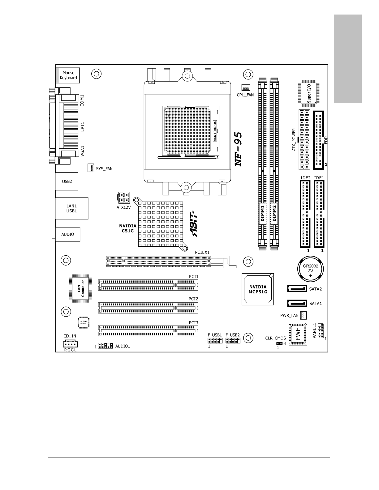
1.2 Motherboard Layout.....................................................................1-3
2. Hardware Setup ............................................................... 2-1
2.1 Choosing a Computer Chassis.......................................................2-1
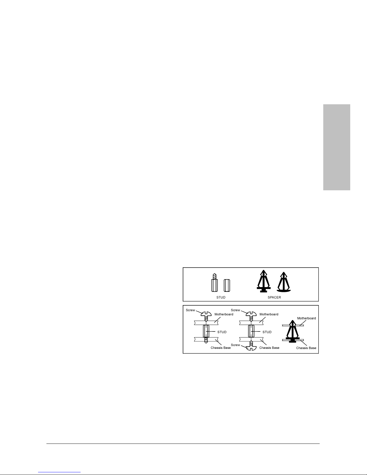
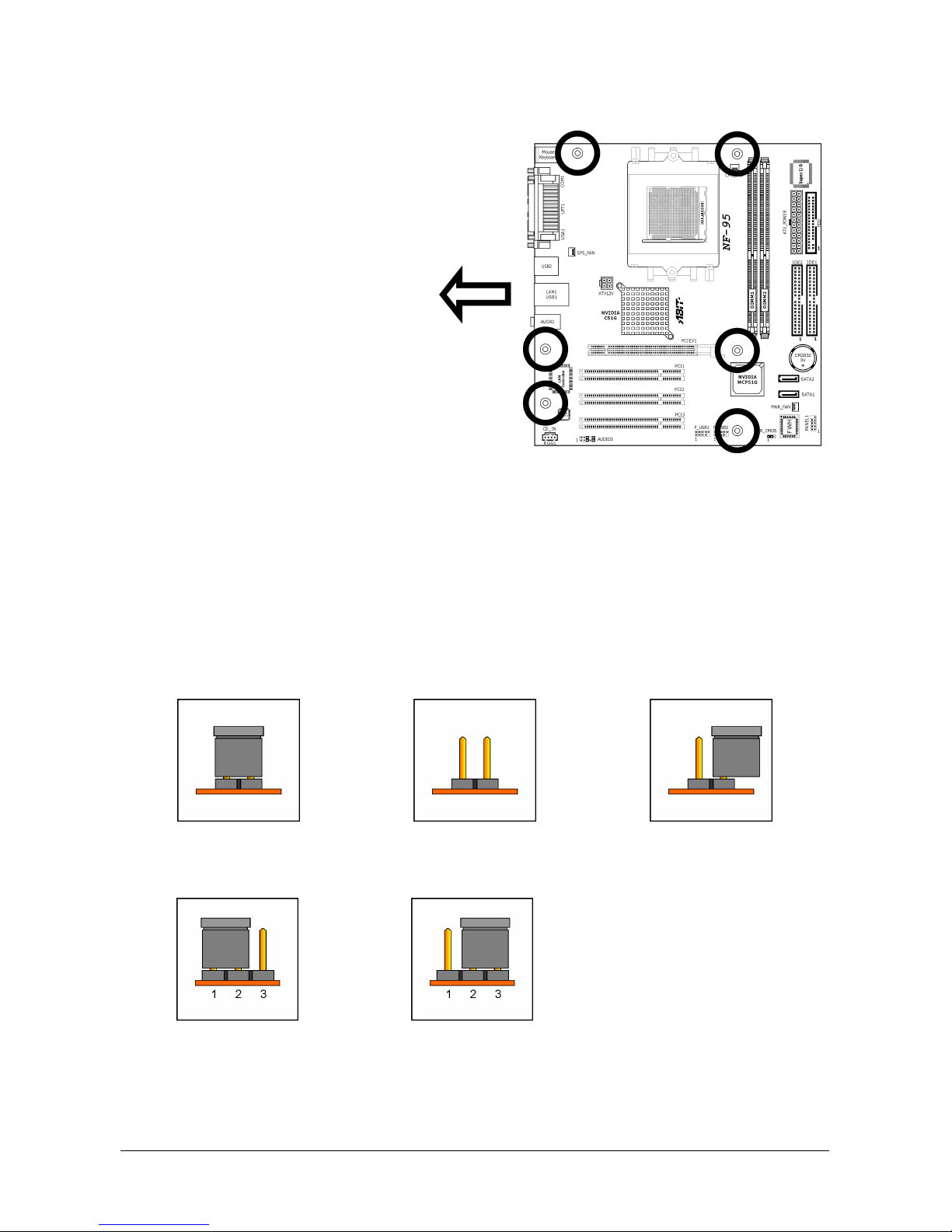
2.2 Installing Motherboard .................................................................2-1
2.3 Checking Jumper Settings ............................................................2-2
2.3.1 CMOS Memory Clearing Header and Backup Battery ..............2-3
2.4 Connecting Chassis Components...................................................2-5
2.4.1 ATX Power Connectors ........................................................2-5
2.4.2 Front Panel Switches & Indicators Headers............................2-6
2.4.3 FAN Power Connectors ........................................................2-7
2.4.4 Front Panel Audio Connection Header ...................................2-8
2.5 Installing Hardware......................................................................2-9
2.5.1 CPU Socket 939 ..................................................................2-9
2.5.2 DDR Memory Slots ............................................................2-12
2.5.3 Floppy and IDE Disk Drive Connectors ................................ 2-14
2.5.4 PCI Express X16 Add-on Slots ............................................2-15
2.5.5 PCI Add-on Slots ...............................................................2-15
2.5.6 Serial ATA Connectors .......................................................2-16
2.6 Connecting Optional Devices ......................................................2-17
2.6.1 Additional USB 2.0 Port Headers.........................................2-17
2.6.2 Internal Audio Connector ...................................................2-18
2.7 Connecting I/O Devices..............................................................2-19
3. BIOS Setup....................................................................... 3-1
3.1 Standard CMOS Features..............................................................3-2
3.2 Advanced BIOS Features ..............................................................3-5
3.3 Advanced Chipset Features...........................................................3-7
3.4 Integrated Peripherals................................................................3-10
3.5 Power Management Setup..........................................................3-14
3.6 PnP/PCI Configurations ..............................................................3-17
3.7 PC Health Status........................................................................3-18
3.8 Load Fail-Safe Defaults ..............................................................3-19
NF-95 iii

3.9 Load Optimized Defaults ............................................................3-19
3.10 Set Password...........................................................................3-19
3.11 Save & Exit Setup ....................................................................3-19
3.12 Exit Without Saving..................................................................3-19
4. Driver & Utility CD............................................................ 4-1
5. Appendix .......................................................................... 5-1
5.1 Troubleshooting (How to Get Technical Support?)..........................5-1
5.1.1 Q & A.................................................................................5-1
5.1.2 Technical Support Form ......................................................5-4
5.1.3 UNIVERSAL ABIT Contact Information ..................................5-5
iv NF-95

Introduction
1. Introduction
1.1 Features & Specifications
CPU
• Socket 939 for AMD Athlon64FX, Athlon64X2, Athlon64, or Sempron Processor with
2000MT/s System Bus
• Support AMD Cool ‘n’ Quiet Technology
Chipset
• Northbridge: NVIDIA C51G (GeForce 6100)
• Southbridge: NVIDIA MCP51G (nForce 410)
Memory
• 2X 184-pin DIMM slots support 2GB maximum memory capacity
• Supports Dual Channel DDR 400/333 Un-buffered ECC memory
Graphics
• Integrated NVIDIA GeForce 6100 controller provides enthusiast-class GeForce 6
graphics features
Serial ATA
• 2x SATA 3Gb/s
• Supports SATA RAID 0, 1, JBOD
LAN
• Onboard 10/100Mb PCI controller
Audio
• Onboard 5.1-Channel Audio CODEC
Expansion Slots
• 1x PCI Express x16 slot
• 3x PCI slots
Internal I/O Connectors
• 1x floppy disk drive connector
• 2x UDMA 133/100/66/33 IDE connectors (each supports 2x IDE devices)
• 2x SATA 3Gb/s connectors
• 2x USB 2.0 headers (each supports 2x USB 2.0 ports)
• 1x FP-Audio header
• 1x CD-IN header
NF-95 1-1

Rear Panel I/O
• 1x PS/2 port for mouse
• 1x PS/2 port for keyboard
• 1x serial port
• 1x parallel port
• 1x VGA port
• 4x USB 2.0 ports
• 1x RJ-45 LAN port
• Audio jacks for line-in, line-out, and microphone
Miscellaneous
• Micro ATX form factor (224mm x 244mm)
※ Specifications and information contained herein are subject to change without
notice.
1-2 NF-95

Introduction
1.2 Motherboard Layout
NF-95 1-3

1-4 NF-95

Hardware Setup
NF-95 2-1
2. Hardware Setup
In this chapter we will elaborate all the information you need upon installing this motherboard
to your computer system.
※ Always power off the computer and unplug the AC power cord before adding or
removing any peripheral or component. Failing to do so may cause severe
damage to your motherboard and/or peripherals. Plug in the AC power cord only
after you have carefully checked everything.
2.1 Choosing a Computer Chassis
• This motherboard carries a Micro ATX form factor of 224 x 244 mm. Choose a chassis big
enough to install this motherboard.
• As some features for this motherboard are implemented by cabling connectors on the
motherboard to indicators and switches or buttons on the chassis, make sure your chassis
supports all the features required.
• If there is possibility of adopting some more hard drives, make sure your chassis has
sufficient power and space for them.
• Most chassis have alternatives for I/O shield located at the rear panel. Make sure the I/O
shield of the chassis matches the I/O port configuration of this motherboard. You can find
an I/O shield specifically designed for this motherboard in its package.
2.2 Installing Motherboard
Most computer chassis have a base with
many mounting holes to allow the
motherboard to be securely attached, and at
the same time, prevent the system from
short circuits. There are two ways to attach
the motherboard to the chassis base:
1. use studs, or
2. use spacers
In principle, the best way to attach the board
is to use studs. Only if you are unable to do
this should you attach the board with spacers.
Line up the holes on the board with the mounting holes on the chassis. If the holes line up and
there are screw holes, you can attach the board with studs. If the holes line up and there are
only slots, you can only attach with spacers. Take the tip of the spacers and insert them into
the slots. After doing this to all the slots, you can slide the board into position aligned with slots.
After the board has been positioned, check to make sure everything is OK before putting the
chassis back on.

To install this motherboard:
1. Locate all the screw holes on
the motherboard and the
chassis base.
2. Place all the studs or spacers
needed on the chassis base
and have them tightened.
3. Face the motherboard’s I/O
ports toward the chassis’s rear
panel.
4. Line up all the motherboard’s
screw holes with those studs o
r
spacers on the chassis.
5. Install the motherboard with
screws and have them
tightened.
Face the chassis’s rear panel.
※ To prevent shorting the PCB circuit, please REMOVE the metal studs or spacers if
they are already fastened on the chassis base and are without mounting-holes
on the motherboard to align with.
2.3 Checking Jumper Settings
For a 2-pin jumper, plug the jumper cap on both pins will make it CLOSE (SHORT). Remove the
jumper cap, or plug it on either pin (reserved for future use) will leave it at OPEN position.
SHORT OPEN OPEN
For 3-pin jumper, pin 1~2 or pin 2~3 can be shorted by plugging the jumper cap in.
Pin 1~2 SHORT Pin 2~3 SHORT
2-2 NF-95

Hardware Setup
NF-95 2-3
2.3.1 CMOS Memory Clearing Header and Backup Battery
The time to clear the CMOS memory occurs when (a) the CMOS data becomes corrupted, (b)
you forgot the supervisor or user password preset in the BIOS menu, (c) you are unable to
boot-up the system because the CPU ratio/clock was incorrectly set in the BIOS menu.
This header uses a jumper cap to clear the CMOS memory and have it reconfigured to the
default values stored in the ROM BIOS.
• Pins 1 and 2 shorted (default): Normal operation.
• Pins 2 and 3 shorted: Clear CMOS memory.
To clear the CMOS memory and load the default values:
1. Power off the system.
2. Set pin 2 and pin 3 shorted by the jumper cap. Wait for a few seconds. Set the jumper cap
back to its default settings --- pin 1 and pin 2 shorted.
3. Power on the system.
4. For incorrect CPU ratio/clock settings in the BIOS, press <Del> key to enter the BIOS setup
menu right after powering on system.
5. Set the CPU operating speed back to its default or an appropriate value.
6. Save and exit the BIOS setup menu.

CMOS Backup Battery:
An onboard battery saves the CMOS memory to keep the BIOS information stays on even after
disconnected your system with power source. Nevertheless, this backup battery exhausts after
some five years. Once the error message like “CMOS BATTERY HAS FAILED” or “CMOS
checksum error” displays on monitor, this backup battery is no longer functional and has to
be renewed.
To renew the backup battery:
1. Power off the system and disconnect with AC power source.
2. Remove the exhausted battery.
3. Insert a new CR2032 or equivalent battery. Pay attention to its polarity. The “+” side is its
positive polarity.
4. Connect AC power source and power on the system.
5. Enter the BIOS setup menu. Reconfigure the setup parameters if necessary.
CAUTION:
※ Danger of explosion may arise if battery is incorrectly renewed.
※ Renew only with the same or equivalent type recommended by the battery
manufacturer.
※ Dispose of used batteries according to the battery manufacturer’s instructions.
2-4 NF-95

Hardware Setup
NF-95 2-5
2.4 Connecting Chassis Components
2.4.1 ATX Power Connectors
These connectors provide the connection from an ATX power supply. As the plugs from the
power supply fit in only one orientation, find the correct one and push firmly down into these
connectors.
ATX 24-Pin Power Connector:
The power supply with 20-pin or 24-pin cables can both be connected to this 24-pin connector.
Connect from pin-1 for either type. However, a 20-pin power supply may cause the system
unstable or even unbootable for the sake of insufficient electricity. A minimum power of 300W
or higher is recommended.
ATX 12V 4-Pin Power Connector:
This 4-pin 12V power connector mainly supplies power to the CPU. Note that the system will
not start without connecting power to this connector.

2.4.2 Front Panel Switches & Indicators Headers
This header is used for connecting switches and LED indicators on the chassis front panel.
Watch the power LED pin position and orientation. The mark “+” align to the pin in the figure
below stands for positive polarity for the LED connection. Please pay attention to connect these
headers. A wrong orientation will only cause the LED not lighting, but a wrong connection of
the switches could cause system malfunction.
Pin Definition Pin Definition
1 HD LED + 2 MSG LED +
3 HD LED - 4 MSG LED -
5 RESET 6 Power Switch
7 RESET 8 Power Switch
9 Reserved
2-6 NF-95

Hardware Setup
NF-95 2-7
2.4.3 FAN Power Connectors
These connectors each provide power to the cooling fans installed in your system.
• CPU_FAN: CPU Fan Power Connector
• SYS_FAN: System Fan Power Connector
• PWR_FAN: Auxiliary Fan Power Connector
※ These fan connectors are not jumpers. DO NOT place jumper caps on these
connectors.

2.4.4 Front Panel Audio Connection Header
This header provides the auxiliary front-oriented microphone and line-out audio connection for
easier access.
Pin Signal Name Function
1 AUD_MIC Front Panel Microphone input signal
2 AUD_GND Ground used by Analog Audio Circuits
3 AUD_MIC_BIAS Microphone Power
4 AUD_VCC Filtered +5V used by Analog Audio Circuits
5 AUD_F_R Right Channel audio signal to Front Panel
6 AUD_RET_R Right Channel Audio signal to Return from Front Panel
7 REVD Reserved
8 Key No Pin
9 AUD_F_L Left Channel Audio signal to Front Panel
10 AUD_RET_L Left Channel Audio signal to Return from Front Panel
2-8 NF-95

Hardware Setup
NF-95 2-9
2.5 Installing Hardware
※ DO NOT scratch the motherboard when installing hardware. An accidentally
scratch of a tiny surface-mount component may seriously damage the
motherboard.
2.5.1 CPU Socket 939
DO NOT touch or bend the delicate pins on the CPU whenever you are holding it.
1. Pull out the socket lever away from the
socket and fully lift it up over 90-degree
angle.
2. Locate and align the triangle mark with
both the CPU and the socket body.
Vertically place the CPU with its pin-side
down into the socket.
Be careful to insert the CPU into the
socket. The CPU only fits in one
orientation with the socket. DO NOT
force the CPU into the socket.
3. After placing the CPU into position, push
the socket lever down into its locked
position to secure the CPU. The lever
clicks when it’s locked into position.

4. The heatsink for CPU may have thermal
interface material attached to its
bottom. If not, applying a few squeeze
of thermal paste to the CPU die will help
to increase the contact.
5. Place the heatsink and fan assembly
onto the retention frame. Match the
heatsink clip with the socket
mounting-lug. Hook the spring clip to
the mounting-lug.
Put the CPU Fan down on the retention
module and snap the four retention legs
of the cooling fan into place.
6. On the other side, push the retention
clip straight down to lock into the plastic
lug on the retention frame.
7. Flip the lever over to lock the heat sink
in place.
2-10 NF-95

Hardware Setup
NF-95 2-11
8. Connect the CPU cooling fan power
cable to the CPUFAN connector on this
motherboard.
※ The installation procedures vary with different types of CPU fan-and-heatsink
assembly. The one shown here is served for demo only. For detailed information
on how to install the one you bought, refer to its installation guidelines.
※ A higher fan speed will be helpful for better airflow and heat-dissipation.
Nevertheless, stay alert to touch any heatsink since the high temperature
generated by the working system is still possible.

2.5.2 DDR Memory Slots
This motherboard provides 2x 184-pin un-buffered DDR SDRAM slots for the installation of
single or dual channel DDR400/333 memory modules maximum up to 2GB capacity.
Table 2-1. Unbuffered DIMM Support For AMD 939-pin Processor
Chip Selects Maximum DRAM Speed
Data Bus
DIMM1 DIMM2 1T 2T
Single Rank N/A DDR400 DDR400
64-bits (Single Channel)
Double Rank N/A DDR400 DDR400
Single Rank Single Rank DDR400 DDR400
128-bits (Dual Channel)
Double Rank Double Rank DDR400 DDR400
※ To reach the optimum performance in dual-channel configurations, install DDR
DIMM pairs at the same density, DRAM technology and bus width for both slots.
2-12 NF-95
Table of contents
Other Abit Motherboard manuals

Abit
Abit NF-M2 NVIEW User manual

Abit
Abit GD8 Pro User manual

Abit
Abit IS-10 Intel Pentium 4 System Board Socket... User manual

Abit
Abit SD7-533 User manual

Abit
Abit VH6 User manual

Abit
Abit IP-95 User manual

Abit
Abit BG7M User manual

Abit
Abit BG7ML User manual

Abit
Abit AR5 User manual

Abit
Abit AMD Athlon 64 System Board Socket 754 User manual