Abit SM5 User manual

Part No:MN-091-B31-91 Rev:1.02
Table of Contents
Chapter 1 Introduction of SM5/SM5-A Features
¬SM5/SM5-A.........................................................................1-2
lSpecifications ....................................................................1-2
lLayout diagram.................................................................1-4
lSystem block diagram.......................................................1-6
Chapter 2 Installing the Mainboard
¬Standard External Connectors................................................2-3
-Jumpers and Switches..........................................................2-10
®Presentation and Installation of the CPU...............................2-11
¯Installing Pipeline Burst SRAM.............................................2-14
°Installing System Memory 【DRAM Memory】................2-15
Chapter 3 Introduction to BIOS
¬CPU setup 【CPU SOFT MENU™】................................3-3
-Standard CMOS Setup Menu................................................3-9
®BIOS Features Setup Menu.................................................3-11
¯Chipset Features Setup Menu...............................................3-17
°Power Management Setup Menu..........................................3-19
±PCI & Onboard I/O Setup...................................................3-23
²Load BIOS Defaults ............................................................3-28
³Load Setup Defaults.............................................................3-28
´Password Setting .................................................................3-29
µIDE HDD Auto Detection....................................................3-30
Appendix A Quick Installation
Appendix B Intel Pentium CPUs
Appendix C AMD-K5 CPUs

Appendix D Cyrix 6x86 CPUs
Appendix E General Discussion about HDD Installation
Appendix F Technical Support
Appendix G Flash BIOS User Instructions

Introduction of SM5/SM5-AFeatures 1-1
Chapter 1 Introduction of
SM5/SM5-A Features
The SM5/SM5-A have been especially designed for File server, Workstation
and Professional users. It can support a wide range of processors, including all Intel
CPUs (P54C) and Intel CPUs with MMX (P55C), as well as all AMD-K5 and
Cyrix 6x86/6x86L CPUs. It also takes into account, as much as possible, all future
CPUs.
This series uses SOFT MENU™ technology, which means that all the
parameters can be configured without using DIP switches or jumpers. The
configuration is entirely achieved through a “Soft Switch” that allows the user to set
CPU speed and operating voltage with ease.
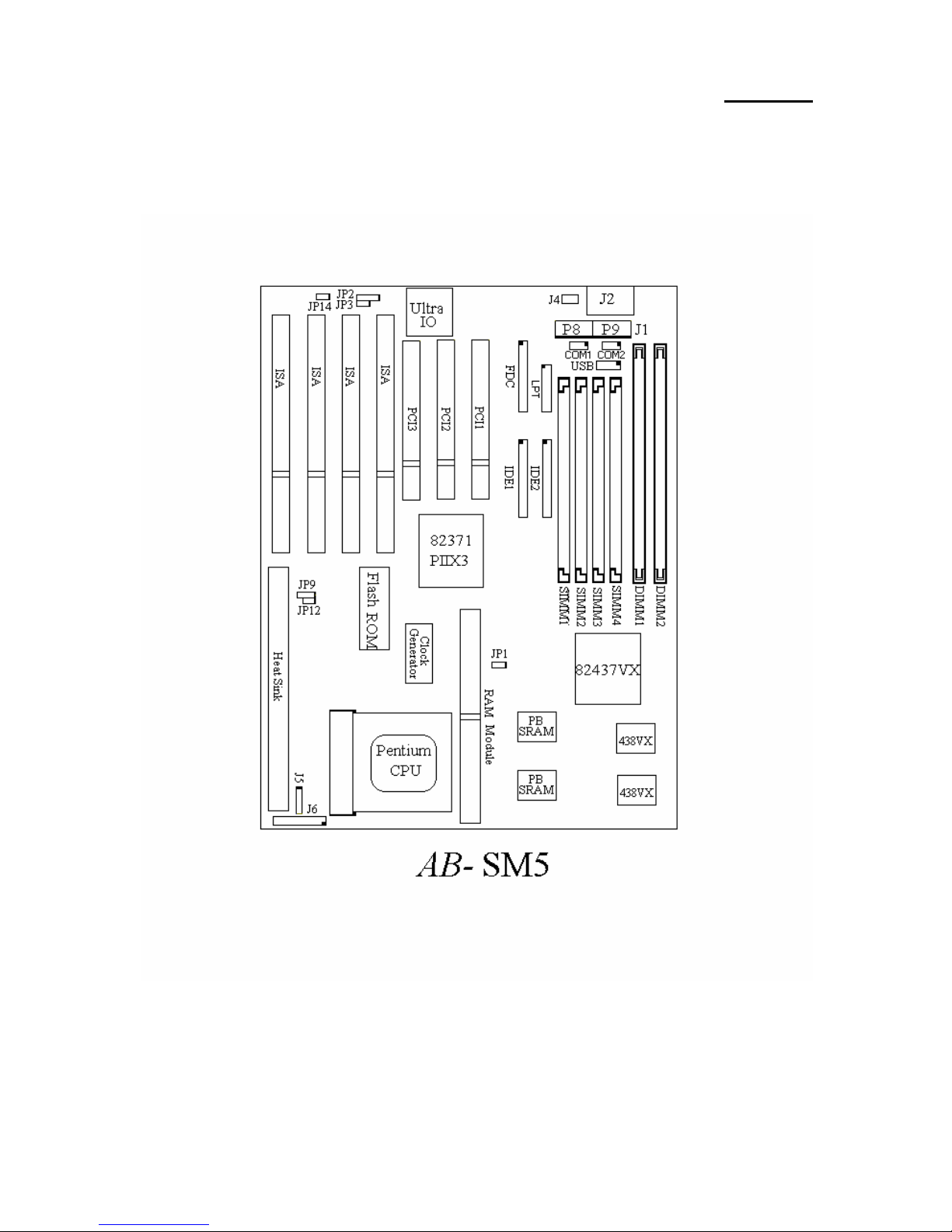
The SM5/SM5-A series uses Intel 430VX series chipsets, and has 256K or
512K Level-2 Pipeline Burst SRAM on board. It also provides an extension slot
allowing the user to upgrade Pipeline Burst SRAM to 512K.
Two 168-pin DIMM slots and four 72-pin SIMM slots meet the requirements
for all memory configurations required by high level computing. The 168-pin
DIMM slots support traditional Fast Page and EDO DRAM as a memory standard
for next generation 64-bit systems. The two 168-pin DIMM slots have been
reserved to meet requirements for both present and future upgrades.
This series also provides two Universal Serial Bus (USB) ports and meets the
Concurrent PCI Rev. 2.1 standard. It also supports IDE interface for Fast HDD
(Mode 0~4), as well as IDE Bus Master. These features also meet present and
future interface standards and needs.
System BIOS features include Plug-and-Play (PnP), Advanced Power
Management (APM), the newest Desktop Management Interface (DMI), as well as
SM5/SM5-A’s unique CPU operating frequency and voltage setup feature in order
to meet modern computing demands.

1-2 Chapter 1
¬SM5/SM5-A
lSpecifications:
1. CPU frequency and voltage setup with CPU “SOFT MENU™”
lSetup of the mainboard’s frequency and voltage without DIP Switches or
Jumpers.
lModification of CPU operating voltage and frequency through software
configuration.
lModification of CPU operating voltage and frequency directly on screen.
2. Uses ZIF CPU Socket 7 for easy CPU installation
lThree voltage regulator/cooling plate sets for a more stable CPU
operating environment
lSupports Intel Pentium®CPUs: 75MHz to 200MHz and P55C CPUs
with MMX
lSupports all AMD sixth generation AMD-K5™CPUs: 75MHz to
166MHz, AMD-K6™CPUs: 200MHz and 233MHz
lSupports all Cyrix sixth generation 6x86™ CPUs: P120+, P133+,
P150+, P166+
lReserved circuitry supports future sixth generation CPUs
3. Chipset
lIntel 430VX chipset
lSupports standard version PCI 2.1
4. L2 Cache Memory
l256K or 512K of cache memory (Pipeline Burst SRAM)
lCache memory upgrade to 512K (the SM5-A do not support this
feature)
5. System DRAM
lFour 72-pin SIMM sockets: support FP and EDO DRAM
lTwo 168-pin DIMM sockets: support FP, EDO and Synchronous
DRAM (SDRAM) (the SM5-A do not support this feature)
lDIMM sockets use PC modules (3.3V Unbuffered DRAM) (the
SM5-A do not support this feature)
lUp to 128MB memory configuration possible

Introduction of SM5/SM5-AFeatures 1-3
6. System BIOS
lAWARD BIOS
lSupports Plug-and-Play (PnP)
lSupports Advanced Power Management (APM)
lSupports Desktop Management Interface (DMI)
7. Multi I/O features
lTwo Universal Serial Bus (USB) ports
lFour fast IDE channels (PIO mode 0~4 and Bus Master)
lOne EPP/ECP parallel port and one 16550 serial port
lTwo floppy disk drive connectors (FDD) (360K, 720K, 1.2M, 1.44M
and 2.88M)
8. Other features
lStandard AT architecture dimensions
lFour ISA bus slots and three PCI bus slots
lSupports 3-MODE for a special Japanese floppy disk drive
lSupports two bootable hard disks--able to run two different operating
systems
Note: All brand names and trademarks are the property of their respective owners.

1-4 Chapter 1
lLayout diagram
Fig 1-1 Layout diagram

Introduction of SM5/SM5-AFeatures 1-5
Fig 1-2 Layout diagram

1-6 Chapter 1
lSystem block diagram
Fig. 1-3 System block diagram
PentiumProcessor
3.3V
Host BUS
Control
Address
Data
Second Level
Cache
Ctrl
Tag Ctrl Data
TIO[0..7]
Addr
Ctrl
PCI BUS TXD Ctrl
Plink
Control
Address/Data
Fast
IDE
ISA BUS
Universal Serial Bus
TDX
Main
Memory
(DRAM)
CACHE
(SRAM)
TAG
TVX
PIIX3
CD ROM &
Hard Disk
USB
1
USB
2
PCI Device(s)
ALi
M5123
ISA Device(s)
Serial
LPT
FDC

Installing the Mainboard 2-1
Chapter 2 Installing the Mainboard
This mainboard series not only provides all standard equipment for classic
personal computers, but also provides great flexibility for meeting future upgrade
demands. This chapter will introduce step by step all the standard equipment and
will also present, as completely as possible future upgrade capabilities. This
mainboard is able to support all Intel Pentium including P55C with MMX, Cyrix
6x86, 6x86L and AMD-K5 processors now on the market. (For details, see
specifications in Chapter 1.) However, we cannot guarantee that the description
given in this manual on the circuitry of your mainboard will work for processors not
listed in Chapter 1. For example, the operating voltage of Cyrix’s next generation
CPUs is unknown at the present time. Thus we were not able to include these
specifications in your motherboard. We will supply further information about CPU
support when new CPUs arrive on the market.
This chapter is organized according the following features:
ŒStandard external connectors
•Jumpers and switches
ŽInstalling the CPU--steps for installing Intel, Cyrix and AMD processors.
•Installing cache memory--If you don’t want to upgrade the cache memory
you can skip this chapter.
•Installing the system memory.
NNNN
Before proceeding with the installation
Before installing the mainboard please be sure to turn off or disconnect the
power supply unit. Before making any modifications to the hardware configuration
of the mainboard, the power supply to any areas of the mainboard you plan to modify
should be turned off to avoid unnecessary damage to the hardware.

2-2 Chapter 2
&
User friendly instructions
Our objective is to enable the novice computer user to perform the installation by
themselves. We have attempted to write this document in a very clear, concise and
descriptive manner to help overcome any obstacles you may face during installation.
Please read our instructions carefully and follow them carefully step-by-step.

Installing the Mainboard 2-3
¬Standard External Connectors
Inside the case of any computer several cables and plugs have to be connected.
These cables and plugs are usually connected one-by-one to connectors located on
the mainboard. You need to carefully pay attention to any connection orientation
the cables may have and, if any, notice the position of the first pin of the connector.
In the explanations that follow, we will describe the significance of the first pin.
Keylock connectorPlease pay attention to pin position and orientation
This connector has a specific orientation. Connect the five-thread keylock
connector cable to the connector pins on the mainboard.
Model name SM5 (J6) SM5-A (J5)
Pin number Name or significance of signal
20 +5VDC
19 No connection
18 Ground
17 Keyboard inhibit Signal
16 Ground
The “keylock switch”is used to lock the computer’s keyboard.
This disables the keyboard so that unauthorized persons cannot
use it. When this function is in use, you will need to use the
unlock key to activate the keyboard.
Hardware Suspend switch
There is no specific orientation. Connect the two-thread hardware suspend plug
to the connector pins on the mainboard. Since most cases do not support this
feature, most of you ignore this instruction. Furthermore, this feature is not
necessary as it is already a part of the mainboard.
Model name SM5 (J6) SM5-A (J5)
Pin number Name or significance of the signal
7Suspend
6Ground
Computer
Knowledge

2-4 Chapter 2
Hardware Reset connector
There is no specific orientation. Connect the two-thread hardware reset cable to
the connector pins on the mainboard.
Model name SM5 (J6) SM5-A (J5)
Pin number Name or significance of signal
1Ground
2Hardware reset signal
The “Hardware Reset”is used to reset the computer during
operation without turning the computer off and back on. For
example, if you are running an application that stops responding to
the computer, you may press the Reset button to restart the
computer.
Speaker connector
There is no specific orientation. Connect the four-thread speaker cable to the
connector pins on the mainboard.
Model name SM5 (J6) SM5-A (J5)
Pin number Name or significance of signal
11 +5VDC
12 Ground
13 Ground
14 Sound Signal
Turbo switch LED connector
This connector has a specific orientation. Connect the two-thread turbo switch
LED plug to the connector pins on the mainboard.
Model name SM5 (J6) SM5-A (J5)
Pin number Name or significance of signal
8Anode terminal of Turbo LED
9Cathode terminal of Turbo LED
The “hardware Turbo LED”indicates the status of hardware
operating speed.
Computer
knowledge
Computer
knowledge

Installing the Mainboard 2-5
IDE LED connector
This connector has a specific orientation. Connect the two-thread IDE LED
connector cable attached to the case to the IDE LED connector on the mainboard.
Model name SM5 (J5) SM5-A (J4)
Pin number Name or significance of signal
1LED’s Cathode
2LED’s Anode
3LED’s Anode
4LED’s Cathode
Standby connector(Option)
There is no specific orientation. Most of the present AT cases do not support this
feature so most of you can ignore this instruction. If your case has a cable for the
Standby feature, you should connect this cable to the connector on the Mainboard.
Model name SM5 (JP12) SM5-A (JP100)
Pin number Name or significance of signal
1Standby power supply【+5VSB】
2Control signal of computer switch of the case
The “standby connector,”unlike the traditional mechanical switch,
is an electronic way to turn the computer’s power off. To use this
feature, the power supply system must permit a shutdown power
supply (+5VSB), support the electronic switch feature, and must
also be used with connector (JP14)SM5/(JP102)SM5-A on the
mainboard. For example, when using Windows 95, your
computer will automatically shut down after having saved your
work when you exit Windows. You do not need to use the
mechanical switch to turn the computer off.
Computer
knowledge

2-6 Chapter 2
Power Control connector(Option)
This has a specific orientation. The present power supply units of AT computer do
not support this feature, so you can ignore this connector. If your power supply unit
features this connector, insert plug the connector, but be sure that the signification of
the signal cable is the same, and be sure to use this feature in connection with the
Standby connector on connector .
Model name SM5 (JP14) SM5-A (JP102)
Pin number Name of the signal or signification
1Power supply control signal 【PS_ON】
2Standby power supply 【+5VSB】
3Ground
CPU Fan power connector
This has a specific orientation. Connect the three-threads CPU fan cable to the Fan
connector.
Model name SM5 (JP9) SM5-A (JP9)
Pin number Name of the signal or signification
1Ground
2+12V
3Ground

Installing the Mainboard 2-7
PS/2 Mouse connectorWatch the pin number and the orientation
This has a specific orientation. Connect the six-threads PS/2 Mouse cable provided
to the Mouse connector on the mainboard.
Model name SM5 (J4) SM5-A (JP3)
Pin number Name of the signal or signification
1Mouse data
2No connection
3Ground
4+5VDC
5Ground
6Mouse clock
The “PS/2 Mouse Port”is different from COM1 or COM2 serial
ports to which you can also connect a Mouse. This mainboard
features an extra PS/2 Mouse port, so when you buy a mouse, be
sure that it is a PS/2 Mouse before connecting it to this port. But if
you cannot find any PS/2 Mouse, you can still use COM1 or
COM2 to connect a serial mouse to your computer.
Keyboard Connector
This has an orientation pin. Connect your keyboard connector to connector on the
mainboard.
Model name SM5 (J2) SM5-A(JP2)
Pin number Name of the signal or signification
1Keyboard clock
2Keyboard data
3No connection
4Ground
5+5VDC
Computer
knowledge

2-8 Chapter 2
Power input Connectors Watch the pin number and the orientation
These have a specific orientation. The three warning marks indicate that if you make a
mistake in pin number or connection orientation, you could destroy your equipment.
During installation, you just need to connect to the correct pins and in the correct
orientation, and to connect connectors P8 and P9 of the power supply unit to the
connectors on the mainboard.
Pin number
Name of the signal or
signification Pin number
Name of the signal or
signification
1POWERGOOD 7Ground
2+5VDC 8Ground
3+12VDC 9-5VDC
4-12VDC 10 +5VDC
5Ground 11 +5VDC
6Ground 12 +5VDC
Infrared remote ConnectorWatch the pin number and the orientation
This has a specific orientation. Your mainboard supports this feature, but you must
buy the infrared remote device as an option.
Model name SM5 (JP2) SM5-A (JP14)
Pin number Name of the signal or signification
1+5VDC
2No connection
3Receive data
4Ground
5Transmit data

Installing the Mainboard 2-9
I/O Port connectors Watch the pin number and the orientation
Connector name Pin number Name of the peripheral connected
IDE 1 40 IDE Channel 1
IDE 2 40 IDE Channel 2
FDC 34 Floppy Disk connector
LPT 26 Parallel port connector
COM1 10 Serial port COM1 connector
COM2 10 Serial port COM2 connector
USB 16 Universal Serial Bus connector

2-10 Chapter 2
-Jumpers and Switches
JP3 (SM5) : Delete the contents of the CMOS
JP1 (SM5-A) : Delete the contents of the CMOS
This jumper is set on pins 1 and 2 at the factory, in order for the computer
to function normally, so please do not change this setting. The main feature
of this jumper is to solve situations where the computer crashes due to
improper usage. For instance:
lYou have forgotten the password you set.
lYou have changed inappropriately the settings in the BIOS menu.
lYou want to change the version of flash BIOS.
All these errors are very serious, you must avoid them. But if you have
made one of these errors, this jumper can save your life. First turn off the
power supply and open the computer case, than place the jumper on pins
2 and 3 in order to save your computer. But if you use your computer
normally, you should not need to use this feature.
After you have deleted the CMOS information, the computer is saved, but you still
have to go back to the BIOS Setup menu, and reset one by one all the
specifications: CPU, date, hour, FDD and HDD parameters. etc., before your
computer will get back into normal operation.
JP1:Installing the cache memory in the cache memory extension slot
(COAST) (the SM5-A do not support this feature)
On delivery, the SM5 mainboard comes with a 256K or 512K cache
memory. If you already have 512K, your mainboard will not need a cache
extension, and you will not be able to see the extension slot. But if you
have only 256K, we have reserved an extension slot which permits you to
extend the cache to 512K. This is set up at the factory with no jumper,
which is what we call OFF status. You will need to put the jumper in place
only when you extend the cache. For more details, refer to the section
which deals with cache memory.

Installing the Mainboard 2-11
®Presentation and Installation of the CPU
Jumperless Mainboard (Mainboard with no DIP Switch or Jumper)
The SM5/SM5-A mainboard can be installed with CPU without the hardware
setting of the CPU.
On other boards, when you want to install the CPU, you have, more or less, to
setup some jumpers or DIP switches. With this mainboard, you will not need to
adjust any jumper or switch. The CPU speed and model is set up by software, in
order to allow the user to complete setup and installation procedures easily. After you
have inserted the CPU on the CPU socket, you can close the computer case and turn
the computer on. You just need to enter the CPU SOFT MENU™located in the
BIOS Setup, and to setup the speed and the voltage of the CPU to compete the
installation. Even if you don’t need to setup any switch, we recommend you to read
our presentation of the CPUs, it will be useful information for you.
Since 1996, every two or three months, Intel adds new models to the Pentium
CPU series. That is why the CPU market is filled with a lot of different models and
brands. All CPUs have different electrical specifications. That’s why installing a CPU
is becoming more and more complex. You can’t help that, because everybody wants
to be able to upgrade its hardware. So, you have to take a bit of time to read this
section, in order to be able to install a cheaper and better processor.
This mainboard does not only support all the CPUs listed in the specifications,
but also has reserved several circuits in order to be able to support future processors.
But before we go further in our presentation, we must clarify that “we have only
tested the CPUs listed in Chapter 1”, we cannot guarantee that this board will be
able to support future products, because we cannot forecast future developments.
But we will do our best to support any possible CPU.
Related terminology :
External clock
Also referred to as the external CPU clock, or “Bus clock”, it is the input clock
of the CPU. For instance, Intel Pentium P90, P120 and P150 all have a
60MHz external CPU clock, but have different internal clock multiplier factors.
Clock multiplier factor
The real operation clock within the CPU is the multiple of the external clock.

2-12 Chapter 2
We refer to this factor as the clock multiplier factor. The four factors possible
are 1.5, 2, 2.5 and 3. The factor differs from one CPU to another. For instance,
the Intel Pentium 166 CPU has a 66MHz external clock, with a multiplier factor
of 2.5, so that the speed of the internal clock is 66MHz x 2.5.
Internal clock
Also referred to as the real internal CPU clock, it is the actual internal operating
clock of the CPU. The Internal Clock is a multiple of the external clock and of
the clock multiplier factor. For instance, the Intel Pentium 90 CPU has a
60MHz external clock and its clock multiplier factor is 1.5; the Intel Pentium
P133 CPU has a 66MHz external clock and its clock multiplier factor is 2.
Internal CPU clock = clock multiplier factor x external CPU clock
AT Bus clock
Also referred to as ISA SPEED, or AT CLOCK, or even ISA Bus clock. Ten
years ago, the original specification of AT Bus clock installed in the first
generation PC/AT computers was 8MHz, this means that there are some
interface cards which can only work at 8MHz. In order to guarantee
compatibility with older hardware, we still support 8MHz AT Bus clock, but if
your interface card is newer or faster, you can choose a higher speed for the
AT Bus clock, in order to increase the transmission rate of the interface cards.
But we recommend you not to be too ambitious. An 8MHz setup ensures
maximum compatibility.
CPU Voltage -Vcore and Vio
From the voltage point of view, 586 series CPU can be divided into two
categories: single voltage CPU and dual voltage CPUs. Single voltage CPUs
include: Intel Pentium P54C series, AMD-K5 and Cyrix 6x86, etc.
Dual voltage CPUs include: Intel P55C with MMX, future AMD CPUs, Cyrix
6x86L and M2.
The voltage of dual voltage CPUs has two components: Vcore and Vio. Vcore
provides all the power for internal processing, and its power consumption is
quite important. Vio provides the power necessary for the external interface of
the CPU.
This manual suits for next models
1
Table of contents
Other Abit Motherboard manuals