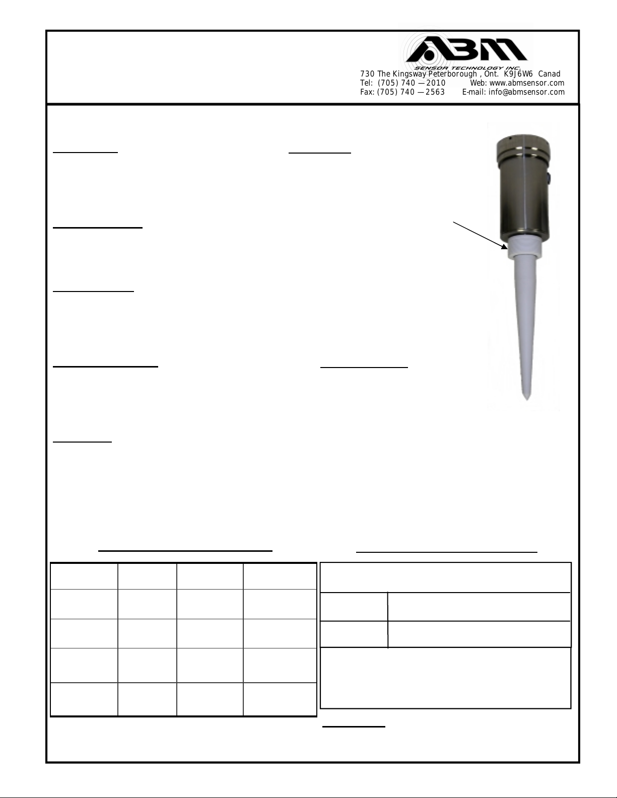
2 Wire Radar Sensors
User Instruction Manual
Calibration — 4 -20 or 20 - 4 mA Output
FULL — Calibrate 20 mA or 4mA (Set Near Target)
1. Calibration mode LED color is blinking Green.
(for Radar Low Dielectric Materials has to be off)
2. Push button and hold until LED turns Yellow (20 mA)
or push button and hold until LED turns Red (4 mA)
3. Release button, observe LED flashes to acknowledge
the calibration.
EMPTY— Calibrate 4 mA or 20 mA (Set Far Target)
1. Calibration mode LED color is blinking Green
(for Radar Low Dielectric Materials has to be off)
2. Push button and hold until LED turns Red (4 mA)
or push button and hold until LED turns Yellow (20 mA)
3. Release button, observe LED flashes to acknowledge
the calibration.
For Radar to turn the Low Dielectric Materials operation mode
ON and OFF (this mode is recommended for materials with
dielectric constant lower than 4 and also to eliminate multiple
reflections in tank.)
1) To turn the Low Dielectric Materials ON. Push button and
hold until LED goes OFF after the sequence of Yellow ,Red
and turns Off. The Low Dielectric Material operation is On
when the LED’S Green light gives two short blinks.
2) To turn the Low Dielectric Materials OFF. Push button and
hold until LED goes OFF after the sequence of Yellow , Red
and Turns OFF. The Low Dielectric Material operation is OFF
when LED is blinking Green.
3) Use “Hart” communication software.
730 The Kingsway Peterborough , Ont. K9J6W6 Canada
Tel: (705) 740 — 2010 Web: www.abmsensor.com
Fax: (705) 740 — 2563 E-mail: info@abmsensor.com
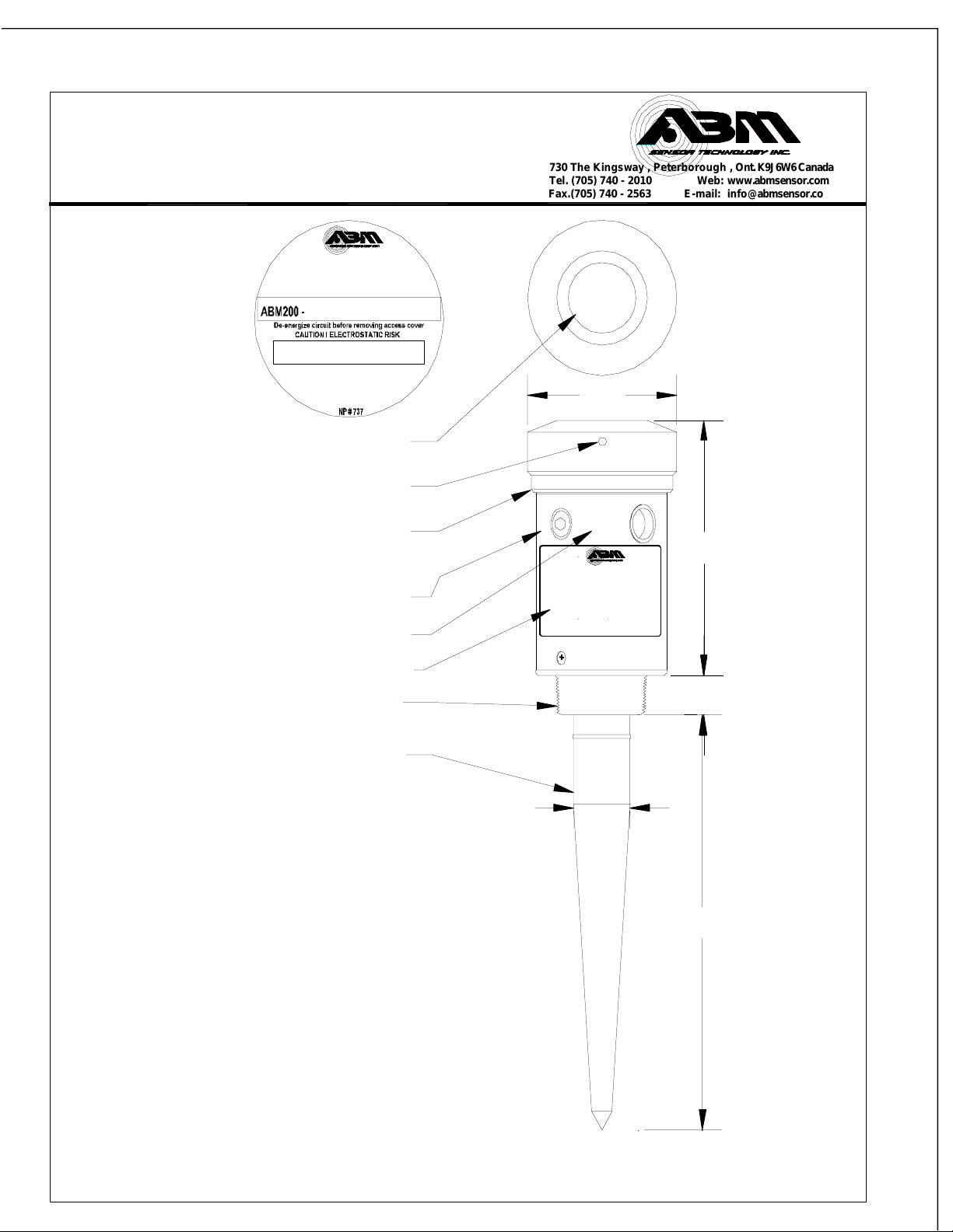
DWG 10A834R1
Fig. # 1 - “2 Wire Sensor” Wiring Connection
Typical Installation
1)Radar unit must be installed into metal fitting with the antenna pointing downward.
Power Input
16 - 30 Vdc
Conduit Entry
1/2” NPT
Process Mtg.
1 1/2”,2”NPT
Radar Rod
Antenna
A
C
C
U
R
A
C
Y
R
E
S
O
L
U
T
I
O
N
Per
Chart
Deadzone
+/—0.25%
EMPTY
4 or
20 or 4 mA
FULL
Level
Material
S
P
A
N
LED
Red
Yellow
Operation - electromagnetic pulse is transmitted from the ABM sensor . The pulse
travels to the surface being monitored and is reflected off this surface back to the
sensor . The time of flight is divided by 2 and converted to an output signal directly
proportional to the material level .
Calibration Pushbutton
Led Indicator For 4 - 20 mA
(750 ohm Max.)
FCC INFORMATION TO RADAR USERS
NOTE: This equipment has been tested and found to comply with the limits for a
Class A digital device, pursuant to Part 15 of the FCC Rules. These limits are
designed to provided reasonable protection against harmful interference when
the equipment is operated in a commercial environment. This equipment gener-
ates, uses, and can radiate radio frequency energy and, if not installed and used
in accordance with the instruction manual, may cause harmful interference to
radio communications. Operation of this equipment in a residential area is likely
to cause harmful interference in which case the user will be required to correct
the interference at his own expense.
WARNING- Changes or Modifications not expressly approved by
ABM Sensor Technology Inc. could void the user’s authority to
operate the equipment.
Wiring Information
- Ground shield at one end only.
- All terminal block wiring must be rated for 250V.
- Terminal is for use only with equipment which has no live parts which
are accessible .
- Terminal is for use with equipment which maintains basic insulation
from hazardous voltage under normal and single fault conditions .
- Connection used at the remote end of external circuit .
Recommended Wiring
- 2 Wire shielded 24 AWG , 300 V
Top View of Sensor (Access Cover Removed)
Status
Calibration Pushbutton
NOTE — Use only
1/2” NPT Conduit
Terminal Block
ABM
SENSOR TECH. INC
STATUS
SWITCH
CALIBRATION
+
—
4-20 mA
V max. = 30 Vdc
V min. = 16 Vdc
Radar 2 Wire
Wire Belden 2 wire Shielded 9501 -
Connect Shield to Ground at one End
RLOAD = Vsup. — 14(V)
25 mA
“2 Wire Radar” Loop Instrumentation
+
-- R Load
Red
Wht. or Blk.
+
--
V supply
16– 30 Vdc
HART
Interface RS232 to PC