Acces PCI-ICM422/2 User manual

ACCES I/O PRODUCTS INC
10623 Roselle Street, San Diego, CA 92121
TEL (858)550-9559 FAX (858)550-7322
MODEL PCI-ICM422(485)/2(4)
USER MANUAL
FILE: MPCI-ICM4S.F1b


Page iii
Notice
The information in this document is provided for reference only. ACCES does not assume any liability
arising out of the application or use of the information or products described herein. This document may
contain or reference information and products protected by copyrights or patents and does not convey any
license under the patent rights of ACCES, nor the rights of others.
IBM PC, PC/XT, and PC/AT are registered trademarks of the International Business Machines Corporation.
Printed in USA. Copyright 2000 by ACCES I/O Products Inc, 10623 Roselle Street, San Diego, CA 92121.
All rights reserved.

Page iv
Warranty
Prior to shipment, ACCES equipment is thoroughly inspected and tested to applicable specifications.
However, should equipment failure occur, ACCES assures its customers that prompt service and support
will be available. All equipment originally manufactured by ACCES which is found to be defective will be
repaired or replaced subject to the following considerations.
Terms and Conditions
If a unit is suspected of failure, contact ACCES' Customer Service department. Be prepared to give the unit
model number, serial number, and a description of the failure symptom(s). We may suggest some simple
tests to confirm the failure. We will assign a Return Material Authorization (RMA) number which must
appear on theouter label of the return package. All units/componentsshould be properly packed for handling
and returned with freight prepaid to the ACCES designated Service Center, and will be returned to the
customer's/user's site freight prepaid and invoiced.
Coverage
First Three Years: Returned unit/part will be repaired and/or replaced at ACCES option with no charge for
labor or parts not excluded by warranty. Warranty commences with equipment shipment.
Following Years: Throughout your equipment's lifetime, ACCES stands ready to provide on-site or in-plant
service at reasonable rates similar to those of other manufacturers in the industry.
Equipment Not Manufactured by ACCES
Equipment provided but not manufactured by ACCES is warranted and will be repaired according to the
terms and conditions of the respective equipment manufacturer's warranty.
General
Under this Warranty, liability of ACCES is limited to replacing, repairing or issuing credit (at ACCES
discretion) for any products which are proved to be defective during the warranty period. In no case is
ACCES liable for consequential or special damage arriving from use or misuse of our product. The
customer is responsible for all charges caused by modifications or additions to ACCES equipment not
approved in writing by ACCES or, if in ACCES opinion the equipment has been subjected to abnormal use.
"Abnormal use" for purposes of this warranty is defined as any use to which the equipment is exposed other
than that use specified or intended as evidenced by purchase or sales representation. Other than the above,
no other warranty, expressed or implied, shall apply to any and all such equipment furnished or sold by
ACCES.

Page v
Table of Contents
Chapter 1: Introduction ..............................................1-1
RS422 Balanced Mode Operation .......................................... 1-1
RS485 Balanced Mode Operation .......................................... 1-1
COM Port Compatibility .................................................. 1-1
Communication Mode ................................................... 1-2
Baud Rate Ranges ..................................................... 1-2
Auto-RTS Transceiver Control ............................................ 1-2
Input/Output Connections ................................................ 1-2
Specifications ......................................................... 1-3
Chapter 2: Installation ..............................................2-1
CD Installation ......................................................... 2-1
3.5-Inch Diskette Installation .............................................. 2-1
Directories Created on the Hard Disk ....................................... 2-2
Installing the Card ...................................................... 2-4
Input/Output Connections ................................................ 2-5
Chapter 3: Option Selection ..........................................3-1
Chapter 4: Address Selection .........................................4-1
Chapter 5: Programming .............................................5-1
Initialization ........................................................... 5-1
Reception ............................................................ 5-3
Transmission .......................................................... 5-4
Chapter 6: Connector Pin Assignments ................................6-1
Appendix A: Application Considerations .............................. A-1
Introduction ...........................................................A-1
Balanced Differential Signals .............................................. A-1
RS485 Data Transmission ...............................................A-3

Page vi
List of Figures
Figure 1-1: PCI-ICM422/2/4 Block Diagram ................................ Page 1-4
Figure 1-2: PCI-ICM485/2/4 Block Diagram ................................ Page 1-4
Figure 3-1: Simplified Termination Schematic .............................. Page 3-1
Figure 3-2: Option Selection Map ........................................ Page 3-3
Figure A-1: Typical RS485 Two-Wire Multidrop Network ...................... Page A-3
List of Tables
Table 5-1: Baud Rate Divisor Values ..................................... Page 5-2
Table 6-1: Connector Pin Assignments ................................... Page 6-1
Table A-1: Connections Between Two RS422 Devices ....................... Page A-1
Table A-2: RS422 Specification Summary ................................. Page A-2

Page 1-1
Manual MPCI-ICM4S.F1b
Chapter 1: Introduction
These cards provide effective asynchronous serial communications in RS422 and RS485 networks
on long communications lines in noisy environments. The cards feature independent serial ports and
use type 16550 buffered UARTs. The data lines are opto-isolated from the computer and from each
other to assure communication through large common mode noise.
Both the RS422 and RS485 cards are 12.283 inches (312 mm) long and may be installed in 5-volt
PCI-bus slots of IBM PC or compatible computers. For Windows compatibility, the cards feature
automatic control in the RS485 mode to transparently enable/disable the transmission drivers.
RS422 Balanced Mode Operation
The PCI-ICM422/2 and PCI-ICM422/4 support RS422 communications and use differential
balanced drivers for long cables and high noise immunity. These cards also have the capability to
add load resistors to terminate the communications lines. RS422 communications requires that a
transmitter supply a bias voltage to ensure a known "zero" state. Also, receiver inputs at each end
of the network should be terminated to eliminate "ringing". These cards support biasing by default
and support termination by jumpers on the card. If your application requires the transmitter to be
un-biased, please contact the factory.
RS485 Balanced Mode Operation
The PCI-ICM485/2 and PCI-ICM485/4 support RS485 communications and also use differential
balanced drivers for long range and high noise immunity. RS485 operation involves switchable
transceivers and the ability to support multiple devices on a single "party line". The RS485
specification defines a maximum of 32 devices on a single line. The number of devices served on
a single line can be expanded by use of "repeaters".
PCI-ICM485/2and PCI-ICM485/4 also have the capability to addloadresistors to properly terminate
the communications lines. Receiver inputs at each end of the network should be terminated to
eliminate 'ringing". Also, RS485communications requires that one transmitter supply a bias voltage
to ensure a known "zero" state when all transmitters are off. These cards support biasing by default
and support termination by jumpers on the card. If your application requires the transmitter to be
un-biased, please contact the factory.
COM Port Compatibility
Type 16550 UARTs are used as the Asynchronous Communication Element (ACE). These include
a16-byte transmit/receive buffer to protectagainst lost data in multitasking operating systems, while
maintaining 100 percent compatibility with the original IBM serial port.

PCI-ICM422/2(4) and 485/2(4) Manual
Page 1-2 Manual MPCI-ICM4S.F1b
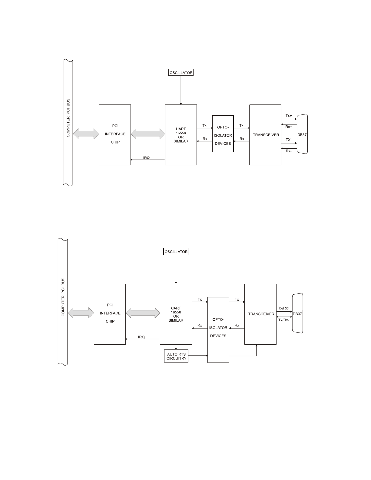
Acrystal oscillator is located on the card. This oscillator permits precise selection of baud rates up
to 115,200 or, by changing a jumper, up to 460,800 with the standard crystal oscillator.
The driver/receiver used, the SN75176B, is capable of driving extremely long communication lines
at high baud rates. It can drive up to ±60 mA on balanced lines and receive inputs as low as a 200
mV differential signal superimposed on common mode noise of +12 V or -7 V. In case of
communication conflict, the driver/receivers feature thermal shutdown.
Communication Mode
PCI-ICM422/2 and PCI-ICM422/4 support Full-Duplex and Half-Duplex communications with a
4-wire cable connection. PCI-ICM485/2 and PCI-ICM485/4 support Half-Duplex communications
with a 2-wire cable connection. Half-Duplex allows traffic to travel in both directions, but only one
way at a time. RS485 communications commonly use the Half-Duplex mode since they share only
a single pair of wires and installation cost is reduced.
Baud Rate Ranges
The card has capability for two baud rate ranges, selectable on a port-by-port basis. One range is
for up to 115,200-baud applications and the other is for up to 460,800-baud applications. Refer to
Baud Rate Divisor Table on page 5-2 of the manual.
Auto-RTS Transceiver Control
In RS485 communications, the driver must be enabled and disabled as needed, allowing all cards to
share a 2-wire cable. The PCI-ICM485/2 and PCI-ICM485/4 cards control the individual drivers
automatically. With automatic control, the driver is enabled when data are ready to be transmitted.
The driver remains enabled after data transmission is complete for one additional character's
transmission time and then is disabled. The receiver is also normally enabled, then disabled during
RS485 transmissions, and then re-enabled after transmission is completed (plus that one character
transmission time). These cards automatically adjust their timing to the baud rate of the data. (The
automatic control feature makes the cards ideal for WIN95 applications)
Input/Output Connections
These cards use a 37-pin DBM connector and a breakout cable. The breakout cable terminates in
aDB9 connector for each port. Those DB9 connectors are equipped with 4-40 threaded standoffs
(female screw lock) to provide strain relief. The mating connector is AMP type 17D-E9s or
equivalent. We recommend using vinyl-jacketed, multiple, twisted-pair cable.

Page 1-3
Manual MPCI-ICM4S.F1b
The card is also available without this cable. If your card was purchased without the cable, there
will be an "S1" appended to the model number.
To ensure that there is minimum susceptibility to EMI and minimum radiation, it is important that
the card mountingbracket be properly screwed into place and that there be a positive chassis ground.
Also, proper EMI cabling techniques (cable connect to chassis ground at the aperture, shielded
twisted-pair wiring, etc) should be used for the input/output wiring.
Specifications
Communications Interface
•I/O Connection: 37 Pin DBM connector.
• Serial Ports: An external breakout cable that terminateswith female D-sub 9-pin
connectors.
•Character length: 5, 6, 7, or 8 bits.
•Parity: Even, odd or none.
•Stop Interval: 1, 1.5, or 2 bits.
•Serial Data Rates: Up to 115,200 baud, asynchronous, A faster range of rates, up to
460,800 baud, is achieved by jumper selection on the card. A type
16550 buffered UART is used and has FIFO buffer.
• Address: Continuously mappable within 0000 to FFFF (hex) range of PCI
bus addresses.
•Receiver Input Sensitivity: ±200 mV, differential input.
•Common Mode Rejection: +12V to -7V.
•Transmitter Output Drive Capability: 60 mA, with thermal shutdown.
Environmental
•Operating Temperature Range: 0 °C. to +60 °C.
•Storage temperature Range: -50 °C. to +120 °C.
•Humidity: 5% to 95%, non-condensing.
•Power Required: +5VDC at 125 mA typical, -12VDC at 5 mA typical, +12VDC at
5mA typical, 750 mW total power consumption (four-port cards).
• Size: 12.283 inches long (312 mm).

PCI-ICM422/2(4) and 485/2(4) Manual
Page 1-4 Manual MPCI-ICM4S.F1b
Figure 1-1: PCI-ICM422/2/4 Block Diagram
(Only one serial channel shown)
Figure 1-2: PCI-ICM485/2/4 Block Diagram

Page 2-1
Manual MPCI-ICM4S.F1b
Chapter 2: Installation
The software provided with this card is contained on either one CD or multiple diskettes and must
be installed onto your hard disk prior to use. To do this, perform the following steps as appropriate
for your software format and operating system. Substitute the appropriate drive letter for your
CD-ROM or disk drive where you see d: or a: respectively in the examples below.
CD Installation
DOS/WIN3.x
1. Place the CD into your CD-ROM drive.
2. Type d:K to change the active drive to the CD-ROM drive.
3. Type installK to run the install program.
4. Follow the on-screen prompts to install the software for this card.
WIN95/98/NT/2000
a. Place the CD into your CD-ROM drive.
b. The CD should automatically run the install programafter 30 seconds. If the install program
does not run, click START | RUN and type d:install, click OK or press K.
c. Follow the on-screen prompts to install the software for this card.
3.5-Inch Diskette Installation
As with any software package, you should make backup copies for everyday use and store your
original master diskettes in a safe location. The easiest way to make a backup copy is to use the DOS
DISKCOPY utility.
In a single-drive system, the command is:
diskcopy a: a:K
You will need to swap disks as requested by the system.
In a two-disk system, the command is:
diskcopy a: b:K
This will copy the contents of the master disk in drive A to the backup disk in drive B.

PCI-ICM422/2(4) and 485/2(4) Manual
Page 2-2 Manual MPCI-ICM4S.F1b
To copy the files on the master diskette to your hard disk, perform the following steps.
a. Place the master diskette into a floppy drive.
b. Change the active drive to the drive that has the diskette installed. For example, if the
diskette is in drive A, type a:K.
c. Type installK and follow the on-screen prompts.
Directories Created on the Hard Disk
The installation process will create several directories on your hard disk. If you accept the
installation defaults, the following structure will exist.
[CARDNAME]
Root or base directory containing the SETUP.EXE setup program used to help you configure
jumpers and calibrate the card.
DOS\PSAMPLES: A subdirectory of [CARDNAME] that contains Pascal samples.
DOS\CSAMPLES: A subdirectory of [CARDNAME] that contains "C" samples.
Win32\language: Subdirectories containing samples for Win95/98 and NT.
WinRISC.exe
AWindows dumb-terminal type communication program designed for RS422/485 operation.
Used primarily with Remote Data Acquisition Pods and our RS422/485 serial communication
product line. Can be used to say hello to an installed modem.
ACCES32
This directory contains the Windows 95/98/NT driver used to provide access to the hardware
registers when writing 32-bit Windows software. Several samples are provided in a variety of
languages to demonstrate how to use this driver. The DLL provides four functions (InPortB,
OutPortB, InPort, and OutPort) to access the hardware.
This directory also contains the device driver for Windows NT, ACCESNT.SYS. This device driver
provides register-level hardware access in Windows NT. Two methods of using the driver are
available, through ACCES32.DLL (recommended) and through the DeviceIOControl handles
provided by ACCESNT.SYS (slightly faster).

Page 2-3
Manual MPCI-ICM4S.F1b
SAMPLES
Samples for using ACCES32.DLL are provided in this directory. Using this DLL not only
makes the hardware programming easier (MUCH easier), but also one source file can be used
for both Windows 95/98 and WindowsNT. One executable can run under both operating
systems and still have full access to the hardware registers. The DLL is used exactly like any
other DLL, so it is compatible with any language capable of using 32-bit DLLs. Consult the
manuals provided with your language's compiler for information on using DLLs in your specific
environment.
VBACCES
This directory contains sixteen-bit DLL drivers for use with VisualBASIC 3.0 and Windows 3.1
only. These drivers provide four functions, similar to the ACCES32.DLL. However, this DLL is
only compatible with 16-bit executables. Migration from 16-bit to 32-bit is simplified because of
the similarity between VBACCES and ACCES32.
PCI
This directory contains PCI-bus specific programs and information. If you are not using a PCI card,
this directory will not be installed.
SOURCE
Autility program is provided with source code you can use to determine allocated resources at
run-time from your own programs in DOS.
PCIFind.exe
Autility for DOS and Windows to determine what base addresses and IRQs are allocated to
installed PCI cards. This program runs two versions, depending on the operating system. Windows
95/98/NT displays a GUI interface, and modifies the registry. When run from DOS or Windows3.x,
atext interface is used. For information about the format of the registry key, consult the
card-specific samples provided with the hardware. In Windows NT, NTioPCI.SYS runs each time
the computer is booted, thereby refreshing the registry as PCI hardware is added or removed. In
Windows 95/98/NT PCIFind.EXE places itself in the boot-sequence of the OS to refresh the registry
on each power-up.
This program also provides some COM configuration when usedwith PCICOM ports. Specifically,
it will configure compatible COM cards for IRQ sharing and multiple port issues.
WIN32IRQ
This directory provides a generic interface for IRQ handling in Windows 95/98/NT. Source code
is provided for the driver, greatly simplifying the creation of custom drivers for specific needs.
Samples are provided to demonstrate the use of the generic driver. Note that the use of IRQs in
near-real-time data acquisition programs requires multi-threaded application programming
techniques and must be considered an intermediate to advanced programming topic. Delphi, C++
Builder, and Visual C++ samples are provided.

PCI-ICM422/2(4) and 485/2(4) Manual
Page 2-4 Manual MPCI-ICM4S.F1b
Findbase.exe
DOS utility to determine an available base address for ISA bus , non-Plug-n-Play cards. Run this
program once, before the hardware is installed in the computer, to determine an available address
to give the card. Once the address has been determined, run the setup program provided with the
hardware to see instructions on setting the address switch and various option selections.
Poly.exe
Ageneric utility to convert a table of data into an nth order polynomial. Useful for calculating
linearization polynomial coefficients for thermocouples and other non-linear sensors.
Risc.bat
A batch file demonstrating the command line parameters of RISCTerm.exe.
RISCTerm.exe
Adumb-terminal type communication program designed for RS422/485 operation. Used primarily
with Remote Data Acquisition Pods and our RS422/485 serial communication product line. Can be
used to say hello to an installed modem. RISCTerm stands for Really Incredibly Simple
Communications TERMinal.
Installing the Card
These cards can be installed in a five-volt PCI slot of an IBM or compatible computer. Before ,
carefully read the Option Selection section of this manual and configure the card according to your
requirements. Finally, our SETUP.EXE program will lead you through the process of setting the
options on the card. The setup program does not set the options. These must be set manually by
jumpers on the card.
To Install the Card
1. Turn OFF computer power.
2. Remove the computer cover.
3. Install the jumpers as shown in the Option Selection section of this manual or the
SETUP.EXE software program.
4. Install the card in an available PCI-bus slot.
5. Replace the computer cover and turn ON the computer.
6. Enter the CMOS setup program of your system and verify that the PCI plug-and-play option
is set appropriately for your system. Systems running Windows95 (or any other
PNP-compliant Operating System) should set the CMOS option to OS. Systems running
under DOS, WindowsNT 3.51, Windows 3.1, or any other non-PNP-compliant Operating
System should set the PNP CMOS option to BIOS or Motherboard. Save the option and
continue booting the system.
Inspect for proper fit of the card and tighten screws. Make sure the card's mounting bracket is
properly screwed into place and that there is a positive chassis ground.

Page 2-5
Manual MPCI-ICM4S.F1b
Input/Output Connections
A37-pin D connector is on the mounting bracket and a three-foot-long breakout cable is included
with the cards. That breakout cable terminates in separate 9-pin DBM connectors; one DB9 per port.
If desired, the cards can be purchased without this breakout cable. In this latter case, an "S1" is
added to the model number to signify absence of the breakout cable; viz PCI-ICM485/4S1.

PCI-ICM422/2(4) and 485/2(4) Manual
Page 2-6 Manual MPCI-ICM4S.F1b

Page 3-1
Manual MPCI-ICM4S.F1b
Figure 3-1: Simplified Termination Schematic
Chapter 3: Option Selection
To help you locate the jumpers described in this section, refer to the Option Selection Map at the
end of this chapter. Operation is determined by jumper installation as described in the following
paragraphs.
Terminations
Atransmission line should be terminated at
the receiving end in its characteristic
impedance. Installing a jumper at the
locations labeled LDO and LDI apply
120Sloads across the transmit (LDO)and
receive (LDI) lines.
In operations where there are multiple terminals, only the ports at each end of the network should
have terminating impedance as described above. Also, for RS485 operation, there must be a bias
on the RX+ and RX- lines. If the PCI-ICM485 card is not to provide that bias in your application,
contact the factory.
Baud Rate Ranges
For each of the ports, jumpers labeled X1 and X4 provide means to select baud rates in either of two
ranges. When in the "X1" position, the baud rate range is up to 115,200 baud. When in the "X4"
position, the baud rate range is 200 to 460,800 baud. Refer to the Baud Rate Divisor Table on page
5-2 of the manual.
Interrupts
Please note that, in Windows NT systems, changes must be made to the system registry to support
IRQ sharing. The following is excerpted from "Controlling Multiport Serial I/O Cards"provided by
Microsoft in the MSDN library, documentid: mk: @ivt: nt40res/ D15/S55FC.HTM, also available
in the WindowsNT Resource Kit.
The Microsoft serial driver can be used to control many dumb multiport serial cards. Dumb
indicates that the control includes no on-board processor. Each port of a multiport card has a
separate subkey under the HKLM\CurrentControlSet\Services\Serial subkey in the registry. In each
of these subkeys, you must add values for DosDevices, Interrupt, InterruptStatus, PortAddress, and
PortIndex because these are not detected by the Hardware Recognizer. (For descriptions and ranges
for these values, see Regentry.hlp, the Registry help file on the WindowsNT Workstation Resource
Kit CD.)

PCI-ICM422/2(4) and 485/2(4) Manual
Page 3-2 Manual MPCI-ICM4S.F1b
For example, if you have a four-port PCI-ICM card configured to use address 0xFC00, 0xFD00,
0xFD80, and 0xFE00 with an interrupt of 05, the values in the Registry are:
Serial2 subkey: Serial4 subkey:
PortAddress = REG_DWORD 0xFC00 PortAddress = REG_DWORD 0xFD80
Interrupt = REG_WORD 5 Interrupt = REG_DWORD 5
DosDevices = REG_SZ COM3 DosDevices = REG_SZ COM5
InterruptStatus = REG_DWORD 0xFC08 InterruptStatus = REG_DWORD 0xFC08
PortIndex = REG_DWORD 1 PortIndex - REG_DWORD 3
Indexed =0 Indexed=0
Serial3 subkey: Serial5 subkey:
PortAddress = REG_DWORD 0xFD00 PortAddress = REG_DWORD 0xFE00
Interrupt = REG_DWORD 5 Interrupt = REG_DWORD 5
DosDevices = REG_SZ COM4 Dos Devices = REG_SZ COM6
InterruptStatus = REG_DWORD 0xFCO8 InterruptStatus = REG_DWORD 0xFC08
PortIndex = REG_DWORD 2 PortIndex = REG_DWORD 4
Indexed=0 Indexed=0
As this example shows, the Interrupt status register, which indicates which port (s) caused an IRQ,
is located at COM A Base Address +8.

Page 3-3
Manual MPCI-ICM4S.F1b
Figure 3-2: Option Selection Map

PCI-ICM422/2(4) and 485/2(4) Manual
Page 3-4 Manual MPCI-ICM4S.F1b
This manual suits for next models
3
Table of contents
Other Acces Network Card manuals
Popular Network Card manuals by other brands

rako
rako WK-HUB instruction manual

Philips
Philips PC Card Kvaser LAPcan user guide

AVM
AVM FRITZ!Card DSL Installation and operation

IBM
IBM Broadcom 10 Gb Gen 2 2-port At-a-glance guide

Cisco
Cisco Modular Gigabit Ethernet Line Card I Installation and configuration

StarTech.com
StarTech.com ST10000SPEXI quick start guide