AccuPel HDG-4000 User manual

HDG-4000 ANALOG/DIGITAL VIDEO CALIBRATION GENERATOR USER MANUAL
AccuPel
HDG-4000 Documentation - User Manual
HDG-4000
Analog/Digital Video
Calibration Generator

HDG-4000 ANALOG/DIGITAL VIDEO CALIBRATION GENERATOR USER MANUAL
AccuPel HDG-4000
Analog/Digital Video
Calibration Generator
USER MANUAL
Version 0.92
Safety Information
• To reduce the risk of electric shock, do not expose the HDG-4000 to rain or moisture. Do not
operate the HDG-4000 with the covers removed.
• Use only the supplied power module. Route power cords so they will not be stepped on or
pinched by anything placed on or against them.
• Keep the HDG-4000 away from wet locations such as bathtubs, sinks, wet basements or
swimming pools.
• Unplug the HDG-4000 before cleaning. Use a damp cloth for cleaning. Do not use cleaning
fluids or aerosols, which could enter the unit and cause damage, fire or electrical shock.
• Do not attempt to calibrate or service this unit. Never remove the covers. Disconnect it and
contact AccuPel directly for service.

HDG-4000 ANALOG/DIGITAL VIDEO CALIBRATION GENERATOR USER MANUAL
2
Table of Contents
INTRODUCTION ........................................................................................................................................ 3
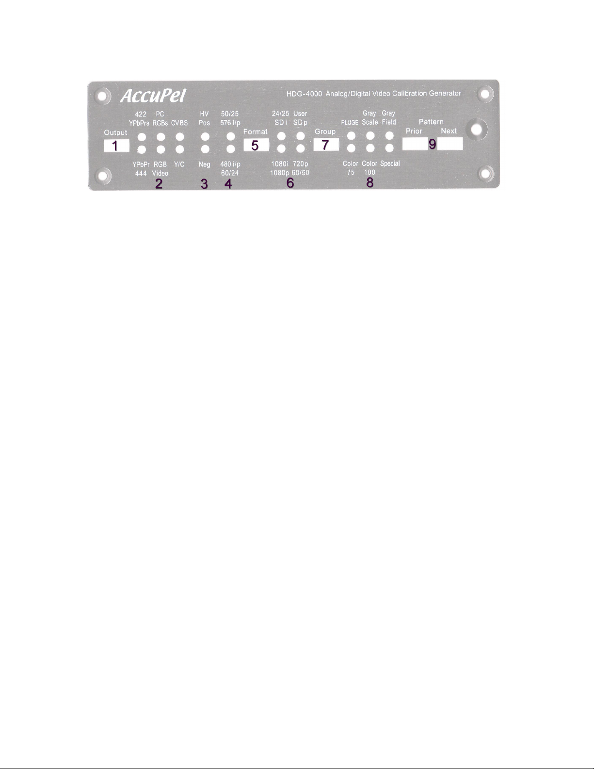
FRONT PANEL CONTROLS .................................................................................................................... 5
LED INDICATORS ..................................................................................................................................... 5
1OUTPUT SELECTOR ............................................................................................................................. 5
2OUTPUT INDICATOR LEDS.................................................................................................................. 6
3SYNC SELECTION ................................................................................................................................ 6
450 HZ / 60 HZ SELECTION................................................................................................................... 6
5FORMAT SELECTOR ............................................................................................................................ 6
6FORMAT INDICATOR LEDS................................................................................................................. 7
7GROUP SELECTOR ............................................................................................................................... 7
8GROUP INDICATOR LEDS................................................................................................................... 7
9PRIOR & NEXT PATTERN SELECTOR BUTTONS ................................................................................... 8
ON SCREEN DISPLAY (OSD) SYSTEMS ............................................................................................... 9
PATTERN INFORMATION............................................................................................................................ 9
OSD MENU SYSTEM ................................................................................................................................. 9
OSD MENU NAVIGATION ......................................................................................................................... 9
OSD MENUS ........................................................................................................................................... 10
SELECTED REMOTE CONTROL FUNCTIONS................................................................................. 11
REAR PANEL I/O...................................................................................................................................... 12
SYNC MODES............................................................................................................................................ 13
STANDARD SYNC MODES........................................................................................................................ 13
AUTOMATICALLY STORED SYNC MODES................................................................................................ 13
TEST PATTERN NOTES ......................................................................................................................... 14
COLOR 75 GROUP ................................................................................................................................... 14
COLOR 100 GROUP ................................................................................................................................. 14
SPECIAL GROUP ...................................................................................................................................... 14
PLUGE GROUP ...................................................................................................................................... 15
GRAY SCALE GROUP - LOW GS, HIGH GS.............................................................................................. 15
GRAY FIELD GROUP................................................................................................................................ 15
CHARACTERISTICS .................................................................ERROR! BOOKMARK NOT DEFINED.
PICTURE FORMATS (59.94 & 60.00 HZ BASED)...................................................................................... 16
PICTURE FORMATS (50.00 HZ BASED).................................................................................................... 17
DIGITAL OUTPUT FORMATS .................................................................................................................... 17
ANALOG OUTPUT FORMATS ................................................................................................................... 18
CALIBRATION PATTERNS ........................................................................................................................ 19
LIMITED WARRANTY............................................................................................................................ 20
Copyright 2007 by AccuPel, LLC
AccuPel is a trademark of AccuPel, LLC. Specifications subject to change without notice.
All Rights Reserved.

HDG-4000 ANALOG/DIGITAL VIDEO CALIBRATION GENERATOR USER MANUAL
3
Introduction
AccuPel HDG-4000 Analog/Digital Video Calibration Generators are professional test equipment exclusively
for commercial or industrial calibration and testing of video monitors, projectors, and signal processors.
Versatile Signal Outputs
The HDG-4000 produces YPbPr and RGB analog component video compliant with EIA/CEA-770.2 (480i/p),
EBU-N10 (480i/576i), and EIA/CEA-770.3 (1080i/p & 720p) standards. YPbPr and RGB analog component
video is also compliant with SMPTE-274M (1080i/p), and SMPTE-296M (720p) standards, except that sync
is present on Y or G signals only in accordance with EIA/CEA consumer standards. The HDG-4000 also
produces Y/C (S-video) and CVBS (Composite) video compliant with NTSC and PAL standards.
The YPbPrs and RGBs analog output modes are intended for compatibility with professional transcoders
and scalers that retain 7.5-IRE black-level setup when converting standard-definition component video with
7.5 IRE setup. The YPbPrs mode is also compatible with DVD players that produce Panasonic MII
component video signals (480i) with black-level setup.
Digital video output signals are compliant with EIA/CEA-861-B (480i/480p/1080i/720p/1080p). Digital RGB
signals are selectable for compatibility with RGB-PC levels or RGB-Video levels. Digital YCbCr 4:2:2 and
YCbCr 4:4:4 signals are provided for compatibility with HDMI inputs.
22 Video Signal Formats
The HDG-4000 produces up to 22 video signal formats. The HDG-4000 L1 (Level 1) produces 16 video
formats including 480i, 480p, 720p59.94, 720p60, 1080i59.94, 1080i60, 1080p59.94, 1080p60,
1080p23.976, 1080p24. 1080p23.976sf, 1080p24sf, 1080p29.97, 1080p30, 1080p47.95, and 1080p48. The
HDG-4000 L2 (Level 2) adds six additional 50 Hz formats including 576i, 576p, 720p50, 1080i50, 1080p25,
and 1080p50.
Digital YCbCr 4:4:4/4:2:2 Signals & Digital RGB Signals With Video and PC Levels
The Digital output produces digital RGB signals and digital YCbCr 4:4:4/4:2:2 signals for DVI or HDMI
inputs. The 8-bit digital RGB signals can be selected to comply with RGB-PC or RGB-Video signal levels.
RGB-PC digital levels are 0-255 for black (0%) to reference white (100%), and therefore below-black or
above reference white RGB-PC levels are not permitted. RGB-Video digital levels are 16-235 for black (0%)
to reference white (100%), and therefore below-black and above reference white (to 109%) RGB-Video
levels are available for PLUGE patterns and dynamic range calibration.
Versatile Sync Options
High-definition (1080i/p & 720p) analog signals have selectable Tri-Level Sync per EIA/CEA-770.3 (sync on
Y or G only) or Bi-Level Sync for compatibility with older video upconverters that lacked Tri-Level sync
generation. Standard-definition (480i/p, 576i/p) signals have Bi-Level sync (on Y or G only per EIA/CEA-
770.2).
Embedded Bi-Level and Tri-Level sync-on-green/sync-on-Y can be disabled for RGB signals. Separate H, V
sync is available with positive or negative polarity for RGB signals, or a special scope trigger output can be
selected to trigger oscilloscopes or other test equipment when using YPbPr or digital video output signals.

HDG-4000 ANALOG/DIGITAL VIDEO CALIBRATION GENERATOR USER MANUAL
4
10-Bit Analog Video DACs & Separate Sync Generation
The YPbPr and RGB analog component video signals, and the Y component of Y/C and CVBS signals, are
generated by 10-bit Digital to Analog Converters from internal 10-bit 4:4:4 YPbPr and RGB digital signals.
The analog embedded sync signals are produced without using any of the 10-bit video DAC dynamic range.
Other generators may trade-off 30% of the video signal resolution to generate sync signals, or use 8-bit
Digital to Analog Converters with less resolution or linearity.
Direct-Drive Digital (D3)Pattern Generation
All video patterns & sync signal timing is generated using three low-noise, high-stability, crystal oscillator
clocks. There are separate oscillators for 480i/p and 576i/p, for 59.94 Hz based high-definition (HD) formats,
and for 50.00/60.00 Hz based HD formats, per applicable SMPTE and EIA/CEA standards. A proprietary
AccuPel 30-bit digital RGB/YPbPr pattern generation IC directly drives precision 10-bit resolution Digital-to-
Analog Converters for analog component video output. Completely separate 24-bit RGB-Video, RGB-PC,
and YCbCr digital values directly drive the digital video output transmitter without any digital truncation or
conversion errors. No clock synthesizers, format converters, color-space converters, or frame buffers are
used to ensure maximum signal accuracy.
Professional Quality Analog Signal Interfaces
True 75-ohm BNC signal outputs provide the highest-quality analog YPbPr or RGB interface to front
projectors and other displays over long cable runs. All analog YPbPr or RGB signals are simultaneously
available through the DVI-I output connector to drive a separate monitor or test system. All video and HV
sync signals are 75-ohm reverse terminated for optimum pulse fidelity.
Infrared Remote Control
The 41-key IR remote control provides dedicated buttons to directly select each Output mode, Format mode,
Pattern Group, and individual patterns within the current group. There are also dedicated rocker buttons to
move forward or backward through Groups or Patterns. A user-defined Pattern List provides the easiest way
to switch back and forth between several patterns as you work. A single button push will store or delete up
to 6 patterns from a Pattern List, and then move forward or backward through the user-defined Pattern List.
The IR remote control also provides dedicated buttons to enter User-defined Luma and Color values, select
special features, and to navigate the On-Screen-Display (OSD) menus.
Detailed documentation for the IR remote control can be downloaded from the AccuPel website at
www.accupel.com.
OSD Menus
OSD (On-Screen-Display) menus provide access to many advanced features including the ability to specify
user defined Luma and Color values, choose Y/C and CVBS chroma bandwidths, enable/disable output
channels, select sync options, set power up default modes, and configure the serial interface ports.
USB & RS-232C Serial Control Interfaces
The USB and RS-232 Serial Control Interfaces provide full operation of all HDG-4000 functions, including
direct selection of each pattern. Complete documentation for the Serial Interfaces can be downloaded from
the AccuPel website www.accupel.com.

HDG-4000 ANALOG/DIGITAL VIDEO CALIBRATION GENERATOR USER MANUAL
5
Front Panel Controls
LED Indicators
Each time power is applied to the HDG-4000 the PLUGE, Gray Scale, and Gray
Field LEDs will illuminate in sequence for about 4 seconds as the generator is
initialized.
All unused Format LEDs blink once when an IR remote control command is
received. All unused Format LEDs blink rapidly 4-times if a currently invalid
command is received. Any slowly blinking LED indicates that a Special Feature
mode (e.g. Slow Edge) is active.
1 Output Selector
The Output button selects the type of analog and digital video signals produced
by the HDG-4000. The YPbPr and RGB analog video signals comply with the
standard-definition (SD) EIA/CEA 770.2 and EBU-N10 standards, and the
EIA/CEA 770.3 high-definition (HD) standards. HD signals also comply with
SMPTE 274M and SMPTE 296M levels and color encoding, but the tri-level sync
is on the Y/G signal only (per the 770.3 consumer standard), unlike the SMPTE
standards that have sync on all three component signals.
The YPbPrs and RGBs signals mimic the behavior of professional upconverters
and scalers that convert standard-definition video with black-level setup to 1080i
or 720p video without removing the setup. The YPbPrs (480i) mode also complies
with the professional Panasonic MII standard, and early DVD players that
included black-level setup on their 480i YPbPr output.
Y/C (S-video) and CVBS (Composite video) standards are only defined for
standard-definition interlaced signals. Therefore, the Y/C and CVBS output modes
produce 480i and 576i (HDG-4000 L2 only) format signals only. When the Y/C or
CVBS output is selected the signal format will automatically change to either 480i
or 576i (depending on whether the previous format was based on 60 Hz or 50 Hz
respectively). The previous format will be restored when the Output type is
changed again, which allows the Output button to cycle “through” the Y/C and
CVBS modes without having to reselect the original Format. Similarly, the Output
type must be changed from Y/C or CVBS before the Format can be changed to
anything other than 480i or 576i.
Digital signals are always available from the DVI-I connector. When the Y/C or
CVBS mode is selected the digital output signals are YCbCr 4:4:4.
YPbPr and RGB
EIA/CEA-770.2, EBU-
N10, EIA/CEA-770.3,
SMPTE274M/296M
YPbPrs and RGBs
Upconverters/scalers,
Panasonic MII,
480i YPbPr with setup
Y/C and CVBS video

HDG-4000 HD/SD/DVI COMPONENT VIDEO CALIBRATION GENERATOR USER MANUAL
6
2 Output Indicator LEDs
YPbPr / 444 – Analog YPbPr and digital YCbCr 4:4:4 signals are selected. The
black level is set to 0-IRE (blanking level). Bi-Level sync is always used for 480i/p
or 576i/p. For 1080i/p or 720p, Tri-Level sync on Y (only) is used by default to
comply with EIA/CEA-770.3. (Bi-level sync can be selected in the OSD menu).
RGB Video – Analog RGB and digital RGB-Video signals are selected. The black
level is set to 0-IRE (blanking level). Analog HV sync polarity, or SoG can be
selected.
YPbPrs - Analog YPbPrs and digital YCbCr 4:2:2 signals are selected. The
analog output black level is set to 7.5-IRE. This mode is compatible with older
DVD players that include black-level setup on their 480i YPbPr output. It is also
compatible with scalers or video converters that output black at 7.5 IRE.
RGBs PC - Analog RGBs and digital RGB-PC signals are selected. The analog
output black level is set to 7.5-IRE. This mode is compatible with scalers or video
converters that output black at 7.5 IRE.
Y/C - Analog Y/C (S-video) signals are selected. Other analog signal outputs are
disabled. The analog black level is set to 7.5-IRE for 480i signals (default), but
there is no black level setup on 576i signals. The 480i black level setup can be
disabled in the OSD Output menu.
CVBS - Analog CVBS (Composite video) signals are selected. Other analog
signal outputs are disabled. The analog black level is set to 7.5-IRE for 480i
signals (default), but there is no black level setup on 576i signals. The 480i black
level setup can be disabled in the OSD Output menu.
3 Sync Selection
In the RGB or RGBs mode, press and hold the Output button for about 1 second
and the front panel HV Pos and Neg LEDs will change to indicate the RGB HV
sync polarity. Hold the Output button until both LEDs are off to select the SoG
mode. The RGB HV sync polarity or RGB SoG (sync-on-green) can also be
directly selected with dedicated buttons on the HDG-4 remote control.
Bi-level embedded sync for HD signals, and HV sync polarity for digital signals
can be selected in the OSD Sync menu.
4 50 Hz / 60 Hz Selection
Select 50 Hz modes (HDG-4000 L2 only) by pressing and holding the Format
button for about 1 second. When the 50 Hz LED illuminates release the Format
button. If you continue to hold the Format button the 50 Hz/60 Hz mode will
alternate about once per second.
5 Format Selector
Press and release the Format button to change the video format in the following
order - 1080i, 720p, SD i, SD p, 1080p60(50), 1080p24(25), and the 1080p User
format (when 60 Hz is selected). The User format can be selected in the OSD
Defaults menu to produce 1080p24sf, 1080p30, or 1080p48. All formats can be
selected directly using the HDG-4 remote control.
YPbPr also selects
digital YCbCr 4:4:4
signals.
RGB also selects
digital RGB-Video
signals.
YPbPrs also selects
YCbCr 4:2:2 signals.
RGBs also selects
RGB-PC signals.
Y/C (S-video) Video
CVBS (Composite)
Video
RGB Sync Polarity &
RGB Sync-on-Green
50 Hz / 60 Hz
Selection
480i, 480p, 720p
& 1080i formats

HDG-4000 HD/SD/DVI COMPONENT VIDEO CALIBRATION GENERATOR USER MANUAL
7
6 Format Indicator LEDs
The SD i LED indicates 480i when the 480i/p LED is illuminated, and 576i when
the 576i/p LED is illuminated. Similarly, the SD p LED indicates 480p and 576p.
The 1080p LED and one other LED, which indicates the 1080p frame rate
(60/50/24/25/User), will be illuminated at the same time to indicate 1080p formats.
7 Group Selector
The Group button selects the group of calibration signal patterns. Repeatedly
pressing the Group key circulates through the pattern groups.
8 Group Indicator LEDs
Color 75 - 9 calibration patterns that include color bars and primary,
complementary, and gray color windows at 75% signal levels. User color values
can be selected from the OSD User Level menu.
Color 100 - 9 calibration patterns that include color bars and primary,
complementary, and gray color fields at 100% signal levels. User color values can
be selected from the OSD User Level menu.
Special - 12 patterns for calibrating and evaluating horizontal and vertical size,
geometry, convergence, contrast, sharpness, and detail enhancement. User
checkerboard luma values can be selected from the OSD User Level menu.
PLUGE - 9 patterns for adjusting black-level, contrast, and grayscale
Gray Scale – 3 Groups of 14 patterns for measuring and adjusting linearity,
gamma, color temperature, and grayscale tracking. The default group includes 14
patterns with 0%-100% luma values in 10% increments. The Low GS group
includes 14 patterns with 0% to 10% luma values in 1% increments, and the High
GS group includes 14 patterns with 100% to 109% luma values in 0.9%
increments. The Low GS and High GS groups are selected from the HDG-4
remote control. User window luma values can also be selected from the OSD
User Level menu.
Gray Field - 8 patterns for measuring and adjusting overscan, full field uniformity,
color temperature and grayscale tracking using full field patterns. User field luma
values can be selected from the OSD User Level menu.
8 pattern groups
89 total patterns

HDG-4000 HD/SD/DVI COMPONENT VIDEO CALIBRATION GENERATOR USER MANUAL
8
Gray Scale Window Values - When the Gray Scale window patterns are
changed (from the front panel or the IR remote control) the PLUGE, Color 75,
Color 100, and Special LEDs temporarily produce a binary code that represents
the luma value of the window. The binary code persists for about 1 second and
will then disappear.
The LED binary display is for the benefit of users connected to devices other than
displays. The OSD Pattern Information provides a direct text display of the
window’s luma value.
Window % Luma Value
(Low GS) (High GS)
PLUGE
LED
Color 75
LED
Color 100
LED
Special
LED
10 (1) (100.9)
On
20 (2) (101.8)
On
30 (3) (102.7)
On
On
40 (4) (103.6)
On
50 (5) (104.5)
On
On
60 (6) (105.4)
On
On
70 (7) (106.3)
On
On
On
80 (8) (107.2)
On
90 (9) (108.1)
On
On
100 (10) (109.0)
On
On
9 Prior & Next Pattern Selector Buttons
Selects the next or prior pattern in the current pattern group.
Gray Scale Window
Values (binary code)
Gray Scale Window
Values (text display)

HDG-4000 HD/SD/DVI COMPONENT VIDEO CALIBRATION GENERATOR USER MANUAL
9
On Screen Display (OSD) Systems
Pattern Information
Info – Each time a pattern is changed the name of the pattern, which includes important
signal identification information, is displayed on-screen for approximately one second.
Press the Info button on the remote control to display the pattern information
continuously. Press the Info button again to resume the default display period.
OSD Menu System
The OSD Menu is produced by all analog and digital outputs, for all signal formats. The
OSD Menu provides additional features such as user definable luma values and colors,
access to advanced signal parameters, communications port control, and the ability to
specify generator power-up default modes.
OSD Menu Navigation
Press the Menu button to display the OSD window, which is organized into three
columns. The left column of the OSD window currently lists six menus – User Level,
Output, Sync, Misc, Com Ports, and Defaults. Use the cursor keys to highlight the
desired menu, and then move into the middle column and highlight a menu item. The
current status of each highlighted menu item is shown in the right column. To change a
setting move into the right column and highlight one of the alternative settings that will
then be listed in that column. In most cases it is not necessary to press the Enter key
unless “Enter” appears in the right column. In that case highlight “Enter” and press the
remote control Enter key to proceed.
Press the Menu button to turn the OSD menu on or off.
The highlighted cursor position in the OSD menu is
maintained when the menu is turned on or off, so it is
easy to turn the menu off when making measurements
or adjusting a calibration setting, and then turn it back
on again to make additional changes to the same
menu item.

HDG-4000 HD/SD/DVI COMPONENT VIDEO CALIBRATION GENERATOR USER MANUAL
10
OSD Menus
User Level
Field – Set a user defined integer luma value for the User Field in the Gray Field
group. Select Factory and press Enter to restore the original 100% User Field. Select
“Cancel” and press Enter to leave the menu without making any change.
Window – Set a user defined integer luma value for the User Window in the Gray
Scale group. Select Factory and press Enter to restore the original 100% User
Window. Select “Cancel” and press Enter to leave the menu without making any
change.
Checkerboard – Set a user defined integer luma value for the User Checkerboard
and User Inverse Checkerboard in the Special group. Select Factory and press Enter
to restore the original 50% User Checkerboards. Select “Cancel” and press Enter to
leave the menu without making any change.
Color – Set user-defined integer R, G, B values for the User Window and User Field in
the Color 75 and Color 100 groups. The “White” bars in the color bar patterns are also
changed to allow comparison with other known colors. Select Factory and press Enter
to restore the original 75% gray and 100% white colors. Select “Cancel” to leave the
menu without making any change.
The HDG-4 Remote Control manual has more information on entering User values.
Output
CVBS/YC – Select 0 IRE or 7.5 IRE black level setup for NTSC (480i) CVBS or Y/C
signals.
Channels – Enable/disable any combination of RGB or YCbCr (YPbPr) output signals.
CVBS C BW – Select the CVBS (composite video) chroma signal bandwidth.
YC C BW – Select the Y/C (S-video) chroma signal bandwidth.
Color Matrix – Select standard YCbCr/YPbPr HD/SD Rec. 709/Rec. 601 color-matrix
encoding, or reverse the encoding (HD/SD Rec. 601/Rec. 709).
HD V Rate – Select 59.94 or 60.00 Hz HD signals.
Sync
HD DVI – Select positive or negative HD digital sync.
SD DVI – Select positive or negative SD digital sync.
HD Y Type – Select Tri-level or Bi-level HD analog YPbPr embedded sync.
HD G Type – Select Tri-level or Bi-level HD analog RGB embedded sync (SoG).
HD HV Time – Select Normal or SMPTE analog RGB HV Sync positioning.
Y/G Phase – Select sub-pixel analog YPbPr embedded sync positioning.
Scope Trigger – Select normal analog HV sync or special V sync for an oscilloscope
trigger.

HDG-4000 HD/SD/DVI COMPONENT VIDEO CALIBRATION GENERATOR USER MANUAL
11
Misc
Info – Serial number, levels, and options information.
Com Ports (See HDG-4000 Serial Interface Manual for details)
RS232 Baud – Baud rate selection.
USB Baud – Baud rate selection.
RS232 Flow – Flow control selection.
Defaults (Power up)
60/50 Hz – Power up in 60 Hz or 50 Hz mode (HDG-4000 L2 only).
RGB Sync – Power up analog RGB signals with SoG, or Positive or Negative HV
sync.
CVBS/YC – Power up with 0 IRE or 7.5 IRE setup for NTSC (480i) CVBS and Y/C
signals.
RS232 Baud – Power up baud rate.
USB Baud – Power up baud rate.
User Format – Power up with front panel User Format set to select 1080p24sf,
1080p30, or 1080p48.
Save Items – Save all of the above power up defaults.
Selected Remote Control Functions
Please read the HDG-4 Remote Control manual for a complete discussion of
additional remote control features including how to enter User Luma & Color
Levels, and User Pattern Lists.
Edge - Selects Fast or Slow analog video edge transitions. The Slow Edge mode
changes the edge transition rate of the HDG-4000 analog signals to a rate chosen
specifically for each video format. The Edge mode only affects analog signals. It does
not affect the digital video output. The currently selected Output LED will blink slowly
when the Slow Edge mode is enabled.
ALT Gray Scale – Press this button combination to select or alternate between 0%-
10% Low-GS (Gray Scale) patterns and 100%-109% High-GS patterns. Press the
Gray Scale button only to return to the 0%-100% Gray Scale patterns. The Gray Scale
LED will blink slowly when the Low-GS or High-GS mode is enabled.
Note: 100%-109% patterns are not available for digital RGB-PC signals because the
maximum signal amplitude is 100% (digital 255) for RGB PC signals.
Mute - This button produces a 0% black field. Press any button on the remote control
(including Mute) to restore the previous pattern.

HDG-4000 HD/SD/DVI COMPONENT VIDEO CALIBRATION GENERATOR USER MANUAL
12
Rear Panel I/O
1 Y/C, CVBS Video Output
The 4-pin mini-DIN output connector provides Y/C (S-video) video signals, and
CVBS (Composite) video signals (on the Y pin). Use an S-video to RCA adapter or
cable to access the CVBS signals.
2 USB Serial Input/Output
USB input/output. Use a Type A to Type A USB cable to connect the HDG-4000 to
a computer or controller. Requires an HDG-4000 USB driver that can be
downloaded from www.accupel.com. (See the HDG-4000 Serial Interface manual
for details.)
3 RS-232 Serial Input/Output
RS-232 input/output. Use a 4-wire telephone extension cable to connect the HDG-
4000 to an RJ-12 to DB-9 adapter at a PC or controller. (See the HDG-4000 Serial
Interface manual for details.)
4 Digital / RGBHV Video Output
The DVI-I connector provides RGB-Video, RGB-PC, YCbCr 4:4:4, or YCbCr 4:2:2
digital video signals, and RGBHV, RGB SoG, or YPbPr analog video signals.
Analog video and sync signals have 75-ohm output impedance and produce
specified signal levels into 75-ohm inputs. If you connect YCbCr 4:2:2 or YCbCr
4:4:4 signals to an HDMI input, the receiving device must have the capability to be
manually set to receive those input signal types - otherwise the receiving device will
automatically be set to accept RGB digital signals.
5 G/Y, B/Pb, R/Pr Video Output
The 75-ohm BNC connectors output YPbPr or RGB (with sync-on-green) video.
Use these outputs with 75-ohm cables for the highest quality video. Signals have
75-ohm output impedance and produce specified levels into 75-ohm inputs.
6 +6V DC Regulated Input
Power from the +6V DC Regulated power module. Use the supplied HDG-4000
power module only. Do NOT any other power module, which invalidates the HDG-
4000 warranty.

HDG-4000 HD/SD/DVI COMPONENT VIDEO CALIBRATION GENERATOR USER MANUAL
13
Sync Modes
Standard Sync Modes
Sync pulses are always embedded in the Y signal for YPbPr analog signals. Sync
pulses may also be embedded in the G signal (sync-on-green - SoG) for RGB
signals (3-wire interface), but it is more common for RGB signal interfaces to use
separate H (horizontal) and V (vertical) sync signals (RGBHV 5-wire interface).
The HV sync signals may have either positive or negative pulse polarity. The
HDG-4000 provides a choice of SoG or positive or negative HV sync polarity for
analog RGB signals.
Standard-definition (480i/p and 576i/p) embedded sync is always Bi-Level (a
negative pulse), but high-definition standards specify Tri-Level embedded sync (a
negative pulse followed immediately by a positive pulse). The HDG-4000 always
initializes with those sync modes. However, some older scalers produce Bi-Level
sync when upconverting SD video to HD formats, so Bi-level sync for HD formats
can be selected in the OSD Sync menu.
Automatically Stored Sync Modes
Unfortunately the sync modes used for SD and HD video are different. SD YPbPr
video always uses Bi-Level sync, while HD YPbPr standards specify Tri-level
sync. Another major difference exists between YPbPr and RGB video. While
YPbPr always uses embedded sync, RGB video usually uses separate HV sync.
These differences would normally make it cumbersome to switch back and forth
between SD and HD formats, or YPbPr and RGB output signals while calibrating
a projector.
The HDG-4000 addresses this problem in two ways. First, it always powers up set
to the most common or standard modes. Secondly, it automatically saves and
restores the previous sync modes when switching Format (SD or HD) or Output
signal type (YPbPr or RGB). The default modes are shown below, and in most
cases will not need to be changed.
Initial Sync Modes vs. Output Type & Format
SD (480i/p, 576i/p)
HD (1080i/p, 720p)
YPbPr/YPbPrs
Bi-Level
HV off
Tri-Level
HV off
RGB/RGBs
No embedded sync
Neg HV Sync
No embedded sync
Neg HV Sync

HDG-4000 HD/SD/DVI COMPONENT VIDEO CALIBRATION GENERATOR USER MANUAL
14
Test Pattern Notes
Color 75 Group
-75% Tri-split Color Bars - Adjust Color Saturation and Hue controls by
matching color bars while individually viewing each primary color. (Use display
controls to enable single primary colors, or view through color filters.) Similar to
SMPTE Color Bars, but offset and split for easier use.
-75% Color Bars - Standard Color Bars
-75% Color Windows (7) – Primary, complementary, and gray windows provide
accurate CIE color measurements by using the same screen area.
Color 100 Group
-100% Tri-split Color Bars - Check Color Saturation & Hue at 100% levels.
-100% Color Bars - Standard Color Bars at 100% levels.
-100% Color Fields (7) - Measure color field uniformity and chroma noise.
User Colors - Replaces 75% and 100% gray colors in both Color 75 and Color 100
group patterns to provide easy comparison with other standard colors.
Special Group
-Cross-Hatch - Low APL pattern to measure geometry & convergence.
-Inverse Cross-Hatch - High APL pattern for geometry & convergence.
-Dual Needle Pulse – Adjust CRT Contrast. Measure short-term CRT high-
voltage stability and check for CRT Scan Velocity Modulation.
-Color Pixel Multiburst - Adjust chroma-luma delay and signal peaking
(Sharpness/Detail Controls). Red/cyan, black/white, and blue/yellow bursts.
1080i/p & 720p - 5,4,3,2,1 pixel bursts - 7.4, 9.3, 12.4, 18.5, 37.1 MHz
480p & 576p – 5,4,3,2,1 pixel bursts - 2.7, 3.4, 4.5, 6.75, 13.5 MHz
480i & 576i –
-Luma Pixel Multiburst - Adjust signal peaking (Sharpness/Detail Controls).
1080i/720p - 5,4,3,2,1 pixel bursts - 7.4, 9.3, 12.4, 18.5, 37.1 MHz
480p & 576p – 5,4,3,2,1 pixel bursts - 2.7, 3.4, 4.5, 6.75, 13.5 MHz
480i & 576i –
-Polyphase Chroma Sweep – Measure Y/C and CVBS Pb & Pr chroma
bandwidth with 1.0, 1.5, 2.0, 2.5, and 3.0 MHz frequency markers.
-CrossHair – Check centering and edge artifacts on lines.
-Sharpness - 1,2,3,4,5 pixel-width black vertical lines, 1,2,3,4,5 pixel-height
(480p/576p/720p/1080p) or 2,4,6,8,10 (480i/576i/1080i) pixel-height black
horizontal lines. Adjust Sharpness, Detail Enhancement. 50% background.
-4x4 100% Checkerboard/Inverse & 4x4 User Level Checkboard/Inverse (4) -
Measure ANSI & m-ANSI contrast ratio at multiple luma levels.

HDG-4000 HDTV COMPONENT VIDEO CALIBRATION GENERATOR USER MANUAL
15
PLUGE Group
-0% APL PLUGE - Calibrate black level and measure black level stability at 0%
Average Picture Level. +/- 4% stripes, 0% background.
-25% APL PLUGE - Calibrate black level and measure black level stability at 25%
Average Picture Level. +/- 4% stripes, 0%/50% split background.
-50% APL PLUGE with 98%/102% PLUGE - Calibrate black level and Contrast
(for LCoS/LCD/DLP displays), and measure black level stability at 50% APL.
+/- 4% & 98%/102% stripes, 0%/100% split background.
-25%, 50%, 75%, 100% Windows w/PLUGE (4) - Calibrate color temperature &
grayscale tracking. +/- 4% PLUGE pattern to ensure black level doesn’t shift
while adjusting grayscale tracking.
-100% Window with 98%/100% PLUGE - Calibrate color temperature &
grayscale tracking. +/- 4% PLUGE pattern to ensure black level doesn’t shift, and
98%/100% vertical bars to ensure peak-white level doesn't clip while adjusting
grayscale tracking on LCoS/LCD/DLP displays.
-50/100 IRE Window with PLUGE - Check 100% window size for CRT blooming
while adjusting Contrast. +/- 4% PLUGE to maintain black-level setting.
Gray Scale Groups - Low GS, High GS values in ()
-10-Step Vertical Gray Scale Linearity - Check grayscale tracking and color
temperature. 0%-100% (0%-10%) (100%-109%) in 10% (1%) (0.9%) steps.
-10-Step Split Vertical Gray Scale Linearity - Check grayscale tracking and
color temperature. 0%-100% (0%-10%) (100%-109%) in 10% (1%) (0.9%) steps
-10-Step Horizontal Gray Scale Linearity - Check grayscale tracking and color
temperature. 0%-100% (0%-10%) (100%-109%) in 10% (1%) (0.9%) steps
-User,10,20,30,40,50,60,70,80,90,100, (User,1,2,3,4,5,6,7,8,9,10), (User,
100.9,101.8,102.7,103.6,104.5,105.4,106.3,107.2,108.1,109.0) % Windows
w/PLUGE - Calibrate color temperature, grayscale, and gamma. PLUGE ensures
black level doesn’t shift while adjusting grayscale tracking. The background of
the High-GS windows is 100% luma to examine a display’s ability to differentiate
levels near 100%.
Gray Field Group
-Low APL Overscan - Measure/adjust overscan and corner/edge geometry,
convergence, and focus. 0% luma background. 0%-7% horizontal and vertical
overscan lines in 1% overscan intervals.
-High APL Overscan - Measure/adjust overscan and corner/edge geometry,
convergence, and focus. 100% luma background. 0%-7% horizontal and vertical
overscan lines in 1% overscan intervals.
-User Luma Level Field – Enter luma value in OSD User Level menu.
-0%, 25%, 50%, 75%, 100% Gray Fields (5) - Measure full-field (on-off,
0%/100%) contrast ratio. Measure flat field uniformity, brightness, and grayscale
tracking with full-field output levels.

HDG-4000 HD/SD/DVI COMPONENT VIDEO CALIBRATION GENERATOR USER MANUAL
16
Characteristics
Picture Formats (59.94 & 60.00 Hz based)
1080p59.94/60
(per EIA/CEA 770.3,
SMPTE 274M
EIA/CEA 861-B)
1920 x 1080 Pixels - Progressive Active Picture Area
2200 x 1125 Pixels - Progressive Total Frame
148.35164 (148.5/1.001) / 148.50000 MHz Pixel Clock Rate
59.94 Hz / 60.00 Hz Frame Rate
1080p47.95/48
(per SMPTE 274M
EIA/CEA 861-B)
1920 x 1080 Pixels - Progressive Active Picture Area
2750 x 1125 Pixels - Progressive Total Frame
148.35164 (148.5/1.001) / 148.50000 MHz Pixel Clock Rate
47.95 Hz / 48.00 Hz Frame Rate
1080p29.97/30
(per SMPTE 274M
EIA/CEA 861-B)
1920 x 1080 Pixels - Progressive Active Picture Area
2200 x 1125 Pixels - Progressive Total Frame
74.17582 (74.25/1.001) / 74.25000 MHz Pixel Clock Rate
29.97 Hz / 30.00 Hz Frame Rate
1080p23.976/24
(per SMPTE 274M
EIA/CEA 861-B)
1920 x 1080 Pixels - Progressive Active Picture Area
2750 x 1125 Pixels - Progressive Total Frame
74.17582 (74.25/1.001) / 74.25000 MHz Pixel Clock Rate
23.97 Hz / 24.00 Hz Frame Rate
1080p23.976/24sf
(per SMPTE 274M
EIA/CEA 861-B)
1920 x 1080 Pixels – Segmented Frame Active Picture Area
2750 x 1125 Pixels – Segmented Total Frame
74.17582 (74.25/1.001) / 74.25000 MHz Pixel Clock Rate
23.97 Hz / 24.00 Hz Frame Rate
1080i59.94/60
(per EIA/CEA 770.3,
SMPTE 274M
EIA/CEA 861-B)
1920 x 1080 Pixels - Interlaced Active Picture Area
2200 x 1125 Pixels - Interlaced Total Frame
74.17582 (74.25/1.001) / 74.25000 MHz Pixel Clock Rate
59.94 Hz / 60.00 Hz Frame Rate
720p59.94/60
(per EIA/CEA 770.3,
SMPTE 296M
EIA/CEA 861-B)
1280 x 720 Pixels Progressive Active Picture Area
1650 x 750 Pixels - Progressive Total Frame
74.17582 (74.25/1.001) / 74.25000 MHz Pixel Clock Rate
59.94 Hz / 60.00 Hz Frame Rate
480p
(per EIA/CEA 770.2
EIA/CEA 861-B)
720 x 480 Pixels - Progressive Active Picture Area
858 x 525 Pixels - Progressive Total Frame
27 MHz Pixel Clock Rate
59.94 Hz (60/1.001) Frame Rate
480i Analog
(per ITU Rec. 601,
SMPTE/EBU N10)
720 x 480 Pixels Interlaced Active Picture Area
858 x 525 Pixels - Interlaced Total Frame
13.5 MHz Pixel Clock Rate
59.94 Hz (60/1.001) Field Rate, 29.97 Hz (30/1.001) Frame Rate
480i Digital
(per EIA/CEA 861-B)
1440 x 480 Pixels Interlaced Active Picture Area
1716 x 525 Pixels - Interlaced Total Frame
27 MHz Pixel Clock Rate
59.94 Hz (60/1.001) Field Rate, 29.97 Hz (30/1.001) Frame Rate

HDG-4000 HD/SD/DVI COMPONENT VIDEO CALIBRATION GENERATOR USER MANUAL
17
Characteristics (cont)
Picture Formats (50.00 Hz based)
1080p50
(per SMPTE 274M
EIA/CEA 861-B)
1920 x 1080 Pixels - Progressive Active Picture Area
2640 x 1125 Pixels - Progressive Total Frame
148.50000 MHz Pixel Clock Rate
50.00 Hz Frame Rate
1080p25
(per SMPTE 274M
EIA/CEA 861-B)
1920 x 1080 Pixels - Progressive Active Picture Area
2640 x 1125 Pixels - Progressive Total Frame
74.25000 MHz Pixel Clock Rate
25.00 Hz Frame Rate
1080i50
(per SMPTE 274M
EIA/CEA 861-B)
1920 x 1080 Pixels - Interlaced Active Picture Area
2640 x 1125 Pixels - Interlaced Total Frame
74.25000 MHz Pixel Clock Rate
50.00 Hz Frame Rate
720p50
(per EIA/CEA 770.3,
SMPTE 296M
EIA/CEA 861-B)
1280 x 720 Pixels Progressive Active Picture Area
1980 x 750 Pixels - Progressive Total Frame
74.25000 MHz Pixel Clock Rate
50.00 Hz Frame Rate
576p
(per EIA/CEA 770.2
EIA/CEA 861-B)
720 x 576 Pixels - Progressive Active Picture Area
864 x 625 Pixels - Progressive Total Frame
27 MHz Pixel Clock Rate
50.00 Hz Frame Rate
576i Analog
(per ITU Rec. 601,
SMPTE/EBU N10)
720 x 576 Pixels Interlaced Active Picture Area
864 x 625 Pixels - Interlaced Total Frame
13.5 MHz Pixel Clock Rate
50.00 Hz Field Rate, 25.00 Hz Frame Rate
576i Digital
(per EIA/CEA 861-B)
1440 x 576 Pixels Interlaced Active Picture Area
1728 x 625 Pixels - Interlaced Total Frame
27 MHz Pixel Clock Rate
50.00 Hz Field Rate, 25.00 Hz Frame Rate
Digital Output Formats
RGB-Video
Digital RGB 16-235 (for 0-100%, 109% maximum)
RGB-PC
Digital RGB 0-255 (for 0-100%, 109% maximum)
YCbCr 4:4:4, YCbCr 4:2:2
Digital Y 16-235 (for 0-100%, 109% maximum)
Digital Cb/Cr 16-240

HDG-4000 HD/SD/DVI COMPONENT VIDEO CALIBRATION GENERATOR USER MANUAL
18
Characteristics (cont)
Analog Output Formats (All signals into 75 ohm loads, all signals include 75 ohm reverse termination)
EIA/CEA 770.2/770.3, SMPTE 274M/296M, SMPTE/EBU N10
YPbPr
Y - 700 mV
Pb/Pr - ±350 mV
RGB
700 mV
MII, Upconverters (with Setup)
YPbPrs
Y - 700 mV peak includes 7.5 IRE Setup
Pb/Pr - ±324 mV
RGBs
700 mV peak includes 7.5 IRE Setup
Y/C, CVBS
Y, CVBS (480i) w/setup
Y, CVBS (480i) no setup
Y, CVBS (576i)
714.3 mV peak includes 7.5 IRE Setup
714.3 mV peak
700 mV peak
YPbPr, RGB Sync Formats (All signals into 75 ohm loads, all signals include 75 ohm reverse termination)
YPbPr, YPbPrs
Bi-Level or Tri-Level Sync
RGB, RGBs
Bi-Level, Tri-Level, or separate HV-, HV+
Tri-Level Sync
EIA/CEA 770.3
±300 mV on Y & G signals only
Bi-Level Sync
-300 mV on Y or G signals only
HV+ Sync
0 to +2.5V
HV- Sync
+2.5 to 0V
Y/C, CVBS Sync Formats (All signals into 75 ohm loads, all signals include 75 ohm reverse termination)
Bi-Level Sync
-286 mV on Y or CVBS signal for 480i
-300 mV on Y or CVBS signal for 576i

HDG-4000 HD/SD/DVI COMPONENT VIDEO CALIBRATION GENERATOR USER MANUAL
19
Characteristics (cont)
Calibration Patterns (89 Patterns)
75% Red/Green/Blue/Cyan/Magenta/Yellow/Gray Windows
Color 75 (9)
75% Color Bars & 75% Tri-Split Bars, User Color Window
75% Red/Green/Blue/Cyan/Magenta/Yellow/Gray Window
Color 100 (9)
100% Color Bars & 100% Tri-Split Bars, User Color Field
100% Red/Green/Blue/Cyan/Magenta/Yellow/Gray Fields
Special (12)
16:9 Crosshatch, 16:9 Inverse Crosshatch, Dual Needle Pulse,
Color Multi-burst, Chroma Color Bandwidth, Luma Multi-burst,
CrossHair, Sharpness, Checkerboard, Inverse Checkerboard,
User Checkerboard, User Inverse Checkerboard
PLUGE (9)
±4% PLUGE with 0%, 25%, 50% Average Picture Level
25%, 50%, 75%, 100% Gray Windows with ±4% PLUGE,
100% Gray Window with ±4 IRE, 98%/100% PLUGE
50%/100% Split Gray Window with ±4%, 98%/100% PLUGE
Gray Scale (14)
0-100 (0-10) (0-109)* % 10-step Vertical Linearity
Low Gray Scale (14)
0-100 (0-10) (0-109)* % 10-step Split Vertical Linearity
High Gray Scale (14)
0-100 (0-10) (0-109)* % 10-step Horizontal Linearity
User, 10,20,30,40,50,60,70,80,90,100 % Windows with ±4% PLUGE
(User, 1,2,3,4,5,6,7,8,9,10 % Windows with ±4% PLUGE)
(User, 100.9,101.8,102.7,103.6,104.5,105.4,106.3,107.2,108.1,109.0
% Windows with ±4% PLUGE) *
* High GS mode not possible for RGB-PC signals
Gray Field (8)
H/V % Overscan, Inverse H/V % Overscan, User Level Field,
0%, 25%, 50%, 75%, 100% Gray Fields
Video Output Connectors (All analog & digital video outputs simultaneously active)
Analog YPbPr, GBR
Three 75-ohm BNCs - G/Y, B/Pb, R/Pr
Analog Y/C, CVBS
4-pin mini-DIN connector
Analog RGBHV
DVI-I connector - R/Pr, G/Y, B/Pb, H sync, V sync
Digital YCbCr, RGB
DVI-I connector - R/Cr, G/Y, B/Cb, Pixel Clock
Control Interfaces
USB
USB Type A connector, full serial interface control of all functions
RS-232C
RJ-12 connector, full serial interface control of all functions
IR Sensor
Front panel infrared receiver provides full control of all functions
(HDG-4 IR remote control included)
Other
Power
100-240 VAC, 50/60 Hz (+/- 3 Hz), less than 6 watts
Size
6.5" (W) x 1.75" (H) x 4.5" (D)
Weight
Approximately 2 lbs, shipping weight approximately 4 lbs.
Other manuals for HDG-4000
1
Table of contents
Popular Portable Generator manuals by other brands

Ametek
Ametek EM TEST compact NX quick start guide

American Fab
American Fab 9000TB Operator's manual

King Canada
King Canada PowerForce KCG-1501GX instruction manual

Johnson Controls
Johnson Controls tyco NG-1 1150 manual

SEFRAM
SEFRAM 4410B quick start guide

Coleman
Coleman Powermate PM0463300.01 installation instructions

Keysight Technologies
Keysight Technologies M8196A Getting started guide

Draper
Draper DGI2000 instructions

McCulloch
McCulloch FG7000MAUD-C Service spare parts list

SIGLENT TECHNOLOGIES
SIGLENT TECHNOLOGIES SDG6000X Series user manual

Nordson
Nordson 100 PLUS FB manual

Generac Power Systems
Generac Power Systems GH-410 Installation guidelines