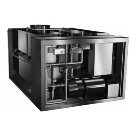
Accurex Vari-Flow User manual

Installation, Operation and Maintenance Manual
Please read and save these instructions for future reference. Read carefully before attempting to assemble, install,
operate or maintain the product described. Protect yourself and others by observing all safety information. Failure
to comply with these instructions will result in voiding of the product warranty and may result in personal injury
and/or property damage.
Vari-Flow Air Management System 1
DANGER
Always disconnect power before working on or
near a unit. Lock and tag the disconnect switch or
breaker to prevent accidental power up.
CAUTION
When servicing the unit, variable frequency drives
(VFD’s) may be hot enough to cause pain or injury.
Allow motor to cool before servicing.
General Safety Information
Only qualified personnel should install this unit.
Personnel should have a clear understanding of these
instructions and should be aware of general safety
precautions. Improper installation can result in electric
shock, possible injury due to coming in contact with
moving parts, as well as other potential hazards.
Other considerations may be required if high winds
or seismic activity are present. If more information
is needed, contact a licensed professional engineer
before moving forward.
1. Follow all local electrical and safety codes, as
well as the National Electrical Code (NEC), the
National Fire Protection Agency (NFPA), where
applicable. Follow the Canadian Electric Code
(CEC) in Canada.
2. Do not allow the power cable to kink or come
in contact with oil, grease, hot surfaces,
or chemicals. Replace cord immediately if
damaged.
3. Verify that the power source is compatible with
the equipment.
Document 473593
Vari-Flow Air
Management System
SYSTEM
FAULT
472618
HOOD
LIGHTS
FAN
ON/OFF
FAN
100%

2Vari-Flow Air Management System
INDOOR — The ideal environment for the storage of
units and accessories is indoors, above grade, in a
low humidity atmosphere which is sealed to prevent
the entry of blowing dust, rain, or snow. Temperatures
should be evenly maintained between 30°F (-1°C) and
110°F (43°C) (wide temperature swings may cause
condensation and “sweating” of metal parts). All
accessories must be stored indoors in a clean, dry
atmosphere.
Remove any accumulations of dirt, water, ice, or snow
and wipe dry before moving to indoor storage. To
avoid “sweating” of metal parts, allow cold parts to
reach room temperature. To dry parts and packages
use a portable electric heater to get rid of any
moisture build up. Leave coverings loose to permit air
circulation and to allow for periodic inspection.
The unit should be stored at least 3½ in. (89 mm) off
the floor on wooden blocks covered with moisture
proof paper or polyethylene sheathing. Aisles between
parts and along all walls should be provided to permit
air circulation and space for inspection.
Inspection and Maintenance during Storage
While in storage, inspect equipment once per month.
Keep a record of inspection and maintenance
performed.
If moisture or dirt accumulations are found on parts,
the source should be located and eliminated.
REMOVING FROM STORAGE — As units are removed
from storage to be installed in their final location,
they should be protected and maintained in a similar
fashion, until the equipment goes into operation.
Prior to installing the unit and system components,
inspect the unit assembly to make sure it is in working
order.
1. Check all fasteners, and accessories for
tightness.
Receiving
Upon receiving the product check to make sure all
items are accounted for by referencing the bill of
lading to ensure all items were received. Inspect
each crate for shipping damage before accepting
delivery. Notify the carrier if any damage is noticed.
The carrier will make notification on the delivery
receipt acknowledging any damage to the product.
All damage should be noted on all the copies of the
bill of lading which is countersigned by the delivering
carrier. A Carrier Inspection Report should be filled out
by the carrier upon arrival and the Traffic Department.
If damaged upon arrival, file claim with carrier. Any
physical damage to the unit after acceptance is not
the responsibility of Accurex.
Unpacking
Verify that all required parts and the correct quantity
of each item have been received. If any items are
missing, report shortages to your local representative
to arrange for obtaining missing parts. Sometimes it
is not possible that all items for the unit be shipped
together due to availability of transportation and truck
space. Confirmation of shipment(s) must be limited to
only items on the bill of lading.
Handling
Handle in such a manner as to keep from scratching
or chipping the coating. Damaged finish may reduce
ability of unit to resist corrosion.
Storage
Units are protected against damage during shipment.
If the unit cannot be installed and operated
immediately, precautions need to be taken to prevent
deterioration of the unit during storage. The user
assumes responsibility of the unit and accessories
while in storage. The manufacturer will not be
responsible for damage during storage. These
suggestions are provided solely as a convenience to
the user.
Table of Contents
Receiving and Handling. . . . . . . . . . . . . . 2
Installation
Control Box Mounting . . . . . . . . . . . . . 3
Resistive Temperature Detector . . . . . . . . 3
Pneumatic Static Pressure Kit . . . . . . . . . . 4
Keypad Mounting . . . . . . . . . . . . . . . . . 4
Wiring . . . . . . . . . . . . . . . . . . . . . . . 5
Wiring Diagrams . . . . . . . . . . . . . . . . 6-7
Connection Checklist . . . . . . . . . . . . . . . 8
Controller Setup . . . . . . . . . . . . . . . . . 8
Controller Display . . . . . . . . . . . . . . . 9-12
Sequence of Operations . . . . . . . . . . . . 13
Daily Operations . . . . . . . . . . . . . . . . 14
System Optimization . . . . . . . . . . . . . . 14
Troubleshooting . . . . . . . . . . . . . . . . 15
Warranty . . . . . . . . . . . . . . . . . . . . . 16

3Vari-Flow Air Management System
NOTE
Resistive temperature detector(s) may be factory
installed. If so, continue to the next section.
Resistive Temperature Detector(s)
(RTD) Mounting
1. Locate flat area(s) at the top interior of the hood
in front of the filters, towards the front of the
hood.
Center the octagon extension over the hole on
the hood surface.
Cut a 3/4-inch diameter hole into the top of
the capture tank. Make sure the resistive
temperature detector(s) will not interfere with fire
system nozzles and is not within 12 inches of
light fixtures.
Installation
Control Box Mounting
1. Locate an area with enough space to mount the
control box and fasten to the wall.
NOTE
All field installation and wiring of electrical
equipment must be done to meet NEC and local
codes.
CENTER THE OCTAGON EXTENSION RING OVER
1/4 inch Compression Seal
Gasket
Temperature
Sensor
Lock Washer
Nut
Octagon Cover
Exhaust Area
Supply Area (optional)
Sensor Install
Cut Out Area
Top View of Exhaust Hood
.75 to .875 inch
diameter hole
Hood
Surface
OcOOca
Octagon
Extension
2. Insert the compression seal into the hole from
the inside of the hood, making sure the gasket
is placed on the fitting before inserting it into
the hole. Install the lock washer and 1-1/2 inch
nut on the threaded portion of the compression
seals and tighten securely.
CENTER THE OCTAGON EXTENSION RING OVER
1/4 inch Compression Seal
Gasket
Temperature
Sensor
Lock Washer
Nut
Octagon Cover
Exhaust Area
Supply Area (optional)
Sensor Install
Cut Out Area
Top View of Exhaust Hood
.75 to .875 inch
diameter hole
Hood
Surface
OcOOca
Octagon
Extension
3. Place the octagon box provided over the fitting
on top of the hood, keeping the fitting centered
in the box.
4. Insert the resistive temperature detector (RTD)
into compression seal and tighten to 35 ft-lbs.
NOTE
Control Box may be factory mounted. If so, continue
to the next section.
NOTE
As the control box contains the static pressure
controls, this control box should be mounted in the
space to be controlled. If the control box is mounted
outside of this space, please refer to the Pneumatic
Static Pressure Kit Installation Instructions.
CENTER THE OCTAGON EXTENSION RING OVER
1/4 inch Compression Seal
Gasket
Temperature
Sensor
Lock Washer
Nut
Octagon Cover
Exhaust Area
Supply Area (optional)
Sensor Install
Cut Out Area
Top View of Exhaust Hood
.75 to .875 inch
diameter hole
Hood
Surface
OcOOca
Octagon
Extension
CENTER THE OCTAGON EXTENSION RING OVER
1/4 inch Compression Seal
Gasket
Temperature
Sensor
Lock Washer
Nut
Octagon Cover
Exhaust Area
Supply Area (optional)
Sensor Install
Cut Out Area
Top View of Exhaust Hood
.75 to .875 inch
diameter hole
Hood
Surface
OcOOca
Octagon
Extension
Top View of Exhaust Hood

4Vari-Flow Air Management System
Pneumatic Static Pressure Kit
1. Locate the Dwyer static pressure sensor outside
of the building in a secure location free from as
many obstructions as possible.
2. Refer to the instruction manual with the static
pressure sensor for installation and operation
details.
3. Once the static pressure probe is mounted, run
vinyl tubing from the probe back to the control
panel and coil the excess tubing. Do not kink or
trim the tubing.
4. If the control panel is located in the space to be
controlled, go to the next section. If the control
panel is mounted remotely from the space to be
controlled, continue to step 5.
5. Run 1/4 inch virgin poly tubing (by others) from
the sensor in the control panel to a secure
location in the space to be controlled.
NOTE
The keypad may be factory mounted. If so, continue
to the next section.
1. For systems with remote controls or keypad, a
25 ft. cable is supplied to connect the keypad
to the controls. The cable is plenum rated and
does not need to be run through conduit unless
required by local codes. If the keypad is to be
mounted further than 25 ft. from the control
box, additional cable will be needed. Cable is
available in 25 ft. lengths from the factory.
Keypad Mounting
Keypad Mounting Diagram
Keypad, screws and wire harness
supplied by the factory
25 ft. cable assembly
supplied by the factory
Two-gang switch box
supplied by the factory
KEYPAD
Connection made at top of Control Panel
If desired, conduit and fittings supplied by
others in field. One-inch conduit needed
to allow smaller connector to fit through.

5Vari-Flow Air Management System
NOTE
All field installation and wiring of electrical
equipment must be done to meet NEC and local
codes.
Control Box
1. Run power to the control box from two
dedicated 120/1 20A breakers to the designated
terminals in the control box (one for lights, one
for controls).
2. If the variable frequency drives(s) are shipped
loose from the control cabinet, please refer
to the VFD wiring section for connection
instructions to the control box.
3. For hood systems connected to a fire system,
the fire system microswitch can be wired into
the designated terminals of the control box for
integration of fire system controls. The factory
default is exhaust on, supply off in fire mode. For
help with changing this parameter, please refer
to the controller setup portion of this manual.
Resistive Temperature Detectors (RTD)
1. Wire the two leads of the sensors to designated
terminals in the control panel as shown below.
For more than four sensors, see wiring diagram
on page 7 or the one inside of control box door.
The two wires of the sensor are not polarity
sensitive. If more than one hood is being
controlled, be sure that the appropriate sensor is
wired in association with the appropriate hood.
Wiring Variable Frequency Drives (VFD)
NOTE
If the VFD(s) are factory supplied and mounted in a
cabinet, all interface wiring is factory supplied and
this first step can be disregarded.
NOTE
If electrically commutated motors are being used,
VFDs will not be needed.
1. If the variable frequency drives are remotely
mounted, a six conductor 18 ga. Class 2 cable
must run between each VFD and the control
panel.
2. Bring power to the input of each VFD from a
dedicated power source using conduit. Each
power source shall be of the same voltage as
the respective fan and of a high enough amp
rating to handle the full load amp draw of the
respective fan.
3. To avoid interference between the conductors,
use separate conduit to wire from the VFD
output to the input power for the fan.
U1
93 - 24V (H)
42 - DO1
51 - DO4
45 - DO2
22 - DI COM
23 - DI2
25 - DI3
24V (C) - 92
DO1 COM - 41
DO4 COM - 53
24VAC
120VAC
R1
Hood Run
A1 A2
RED
Fault Indicator
GRN
Full Speed Indicator
21 - DI1
Full Speed
Fan On/Off
R3
14
11
Hood Lamp(s)
AR
Hood Light Contactor
N
H
TR1
L4
L3
PB3
PB2
Hood Lights Switch
PB1
AR
2 3
6
Hood Lights Relay
R1
Hood Run Contact
1411
GRN
Hood Run Indicator
L1
7
4
6
15
14
913
11
H1 N1
Canopy Lighting circuit must not exceed 15A total current
AVPS - 13
31 - DI7 Fan Override
33
32
NOC
44
45
46
47
48
49
PS1
PRESSURE
12
3
R5
Hood Light LED
Relay
A1 A2
R5
Hood Light LED Contact
1411
GRN
Hood Light Indicator
L2
2
HL
DO2 COM - 44
12 - AI5
1 - AICOM
V1
VC
GGH 20/VAV Fan Mode
0 VDC - Fan Auto
5 VDC - Fan OFF
10 VDC - Fan On for Dry
+ VDC
COM
Interlock Connection
G
BK 14GA
16GA RD 16GA RD
PR BK
BL
BL
BL BL
YW
OR
OR
BL
YW
PR
OR
BR
BL
YW
OR
+-
0
NEUTRAL
BR
OR
RD
DI5 - 28
DI COM - 22
AO4 - 78
AO COM - 71
AI6 - 15
BL
R2
Hood Run
A1 A2
BL
R3
MUA Run
A1 A2 48 - DO3
YW
1 - AICOM
2 - AI1
5 - AI2
T1
T2 17
16
19
18
1
21
20 7 - AI3
T3
BR
OR
OR
OR
10 - AI4
T4
23
22 OR
LL+
LL-
COM
R1
24
21
AICOM - 1
AO1 - 72
AO COM -71
AO2 - 74
AO3 - 76
DI COM - 22
DI4 - 26
24V (C) - 92
R4
1411
R4 Shunt Trip Contact
Open on Shunt Trip
24
21
36
37 }
Fire Contact
24 VAC
24 VAC
24 VAC
120 VAC
24 VAC
EARTH - 91
40
41
42
43
Fire System
35 34
REMOVE
JUMPER
IF USED
R4
Fire & Shunt
Trip Relay
A1 A2
24 VAC
38
39
}
PR
PR
50
51
Tempering Status
Contact
Closed Tempering On
Open Tempering Off
BL
YW
YW
YW
BR
YW
OR
OR
OR
OR
OR
PR
PR
PR
PR PR
BL
30 - DI6
29 - DI COM
PR
PR
PR
PR
RD
OR
BR
GN
RD
RD
34
31
56
57
52
53
54
55
OR
RD
RD
R1
RD
RD
OR
MC
MB
SC
S1
AC
A1
VFD
MUA1
L1
L2
L3
T1
T2
T3
}
}
LINE
LOAD
MC
MB
SC
S1
AC
A1
VFD
L1
L2
L3
T1
T2
T3
}
}
LINE
LOAD
EF1
AC
A1
MC
MB
SC
S1
L1
L2
L3
T1
T2
T3
}
}
LINE
LOAD
VFD
EF2
MC
MB
SC
S1
L1
L2
L3
T1
T2
T3
}
}
LINE
LOAD
AC
A1
VFD
EF3
R2
14
11
62
63
58
59
60
61
RD
RD
U1
24VAC
120VAC
R1
Hood Run
A1 A2
RED
Fault Indicator
GRN
Full Speed Indicator
Full Speed
Fan On/O
R3
14
11
AR
Hood Light Contactor
N
H
TR1
L4
L3
PB3
PB2
Hood Lights Switch
PB1
AR
2 3
6
Hood Lights Relay
R1
Hood Run Contact
1411
GRN
Hood Run Indicator
L1
7
4
6
15
14
9 13
11
H1
Canopy lighting circuit must not exceed 15A total current
Fan Override
33
32
NOC
38
39
40
41
PS1
PRESSURE
12
3
R5
Hood Light LED Contact
1411
GRN
Hood Light Indicator
L2
2
V1
VC
GGH20/VAV Fan Mode
0VDC - Fan Auto
5VDC - Fan OFF
10VDC - Fan On for Dry
+ VDC
COM
Interlock Connection
G
BK 14GA
PR BK
BL
BL
BL BL
YW
OR
OR
BL
YW
PR
OR
BR
BL
YW
OR
+-
o
NEUTRAL
BR
OR
RD
BL
R2
Hood Run
A1 A2
BL
R3
MUA Run
A1 A2
YW
T1
T2
1716
1918
1
2120
T3
BR
OR
OR
OR
T4
2322 OR
R1
24
21
R4
14
11
R4 Shunt Trip Contact
Closes on Shunt Trip
22
21
36
37
Fire Contact
24 VAC
24 VAC
24 VAC
24 VAC
48
49
50
51
Fire System
35 34
REMOVE JUMPER IF USED
R4
Fire & Shunt Trip Relay
A1 A2
24 VAC
44
45
PR
PR
47
46
Tempering Status Contact
Closed Tempering On
Open Tempering O
BL
YW
YW
YW
BR
YW
OR
OR
OR
OR
OR
PR
PR
PR
PR PR
BL
PR
PR
PR
PR
RD
OR
BR
GN
RD
RD
34
31
58
59
54
55
56
57
OR
RD
RD
R1
RD
RD
OR
REMOVE JUMPER
IF USED
93-24V (H)
42-DO1
51-DO4
45-DO2
12-AI5
1-AICOM
48-DO3
1-AICOM
2-AI1
5-AI2
7-AI3
10-AI4
30-DI6
29-DI COM
80-AOV HOT
35-DIV HOT DI COM-22
DI2-23
DI3-25
24V (C)-92
DO1 COM-41
DO4 COM-53
DI1-21
AVPS-13
DI7-31
DO2 COM-44
DI5-28
DI COM-22
AO4-78
AO COM-71
AI6-15
AICOM-1
AO1-72
AO COM-71
AO2-74
AO3-76
DI COM-22
DI4-26
EARTH-91
AOV COM-79
DIV COM-34
DO3 COM-47
BL
BL
BL
YW
YW
YW
Hood Lamp(s)
N1
R5
Hood Light LED Relay
A1 A2
HL
16GA RD 16GA RD
120 VAC
52
53
MC
MB
SC
S1
AC
A1
VFD
MUA1
L1
L2
L3
T1
T2
T3
LINE
LOAD
24V (C)-92
24V (H)-93
R3
24
21
42
43
BL
YW
}
24 VAC FAN ENABLE
TO MUA
MC
MB
SC
S1
AC
A1
VFD
L1
L2
L3
T1
T2
T3
LINELOAD
EF1
AC
A1
MC
MB
SC
S1
L1
L2
L3
T1
T2
T3
LINELOAD
VFD
EF2
MC
MB
SC
S1
L1
L2
L3
T1
T2
T3
LINELOAD
AC
A1
VFD
EF3
R2
14
11
64
65
60
61
62
63
RD
RD
}
}
}
}
}
}
}
}
}
}
}
9/3/2010
Turned o several layers; Borders/Legend.
Adjusted the text so it would be readable.
Was overlapping on lines.
Changed line weight.
Changed to Black/CMYK.
Converted from a .dwg drawing.
NOTE
The RTD’s should not be exposed to direct flame.
The RTD’s are rated up to 250°F
NOTE
The VFD input voltage parameter (E1-01) and motor
overload parameter (E2-01) need to be set to the
motor nameplate FLA. Refer to the Quick Start
Guide from Yaskawa (pages 83-100) for setting these
parameters on the Yaskawa drive.
NOTE
Be sure to use appropriately sized wire for the full
load amp draw.

6Vari-Flow Air Management System
Wiring Diagram - Base System, all options
NOTE
This is an example of a wiring diagram for a base system. Controlling up to 3 exhaust fans, 1 supply fan and 4
temperature sensors. To see your job specific drawing, look on the inside panel of the Vari-Flow cabinet.
U1
24VAC
120VAC
R1
Hood Run
A1 A2
RED
Fault Indicator
GRN
Full Speed Indicator
Full Speed
Fan On/O
R3
14
11
AR
Hood Light Contactor
N
H
TR1
L4
L3
PB3
PB2
Hood Lights Switch
PB1
AR
2 3
6
Hood Lights Relay
R1
Hood Run Contact
1411
GRN
Hood Run Indicator
L1
7
4
6
15
14
9 13
11
H1
Canopy lighting circuit must not exceed 15A total current
Fan Override
33
32
NOC
38
39
40
41
PS1
PRESSURE
12
3
R5
Hood Light LED Contact
1411
GRN
Hood Light Indicator
L2
2
V1
VC
GGH20/VAV Fan Mode
0VDC - Fan Auto
5VDC - Fan OFF
10VDC - Fan On for Dry
+ VDC
COM
Interlock Connection
G
BK 14GA
PR BK
BL
BL
BL BL
YW
OR
OR
BL
YW
PR
OR
BR
BL
YW
OR
+-
o
NEUTRAL
BR
OR
RD
BL
R2
Hood Run
A1 A2
BL
R3
MUA Run
A1 A2
YW
T1
T2
1716
1918
1
2120
T3
BR
OR
OR
OR
T4
2322 OR
R1
24
21
R4
14
11
R4 Shunt Trip Contact
Closes on Shunt Trip
22
21
36
37
Fire Contact
24 VAC
24 VAC
24 VAC
24 VAC
48
49
50
51
Fire System
35 34
REMOVE JUMPER IF USED
R4
Fire & Shunt Trip Relay
A1 A2
24 VAC
44
45
PR
PR
47
46
Tempering Status Contact
Closed Tempering On
Open Tempering O
BL
YW
YW
YW
BR
YW
OR
OR
OR
OR
OR
PR
PR
PR
PR PR
BL
PR
PR
PR
PR
RD
OR
BR
GN
RD
RD
34
31
58
59
54
55
56
57
OR
RD
RD
R1
RD
RD
OR
REMOVE JUMPER
IF USED
93-24V (H)
42-DO1
51-DO4
45-DO2
12-AI5
1-AICOM
48-DO3
1-AICOM
2-AI1
5-AI2
7-AI3
10-AI4
30-DI6
29-DI COM
80-AOV HOT
35-DIV HOT DI COM-22
DI2-23
DI3-25
24V (C)-92
DO1 COM-41
DO4 COM-53
DI1-21
AVPS-13
DI7-31
DO2 COM-44
DI5-28
DI COM-22
AO4-78
AO COM-71
AI6-15
AICOM-1
AO1-72
AO COM-71
AO2-74
AO3-76
DI COM-22
DI4-26
EARTH-91
AOV COM-79
DIV COM-34
DO3 COM-47
BL
BL
BL
YW
YW
YW
Hood Lamp(s)
N1
R5
Hood Light LED Relay
A1 A2
HL
16GA RD 16GA RD
120 VAC
52
53
MC
MB
SC
S1
AC
A1
VFD
MUA1
L1
L2
L3
T1
T2
T3
LINE
LOAD
24V (C)-92
24V (H)-93
R3
24
21
42
43
BL
YW
}
24 VAC FAN ENABLE
TO MUA
MC
MB
SC
S1
AC
A1
VFD
L1
L2
L3
T1
T2
T3
LINELOAD
EF1
AC
A1
MC
MB
SC
S1
L1
L2
L3
T1
T2
T3
LINELOAD
VFD
EF2
MC
MB
SC
S1
L1
L2
L3
T1
T2
T3
LINELOAD
AC
A1
VFD
EF3
R2
14
11
64
65
60
61
62
63
RD
RD
}
}
}
}
}
}
}
}
}
}
}
9/3/2010
Turned o several layers; Borders/Legend.
Adjusted the text so it would be readable.
Was overlapping on lines.
Changed line weight.
Changed to Black/CMYK.
Converted from a .dwg drawing.

7Vari-Flow Air Management System
Wiring Diagram - Expanded System, all options
NOTE
This is an example of a wiring diagram for an expanded system, controlling up to 5 exhaust fans, 8 temperature
sensors and 1 supply fan. For a job specific drawing, look on the inside panel of the Vari-Flow cabinet.
U1
24VAC
120VAC
R1
Hood Run
A1 A2
RED
Fault Indicator
GRN
Full Speed Indicator
Full Speed
Fan On/O
R3
14
11
AR
Hood Light Contactor
N
H
TR1
L4
L3
PB3
PB2
Hood Lights Switch
PB1
AR
2 3
6
Hood Lights Relay
R1
Hood Run Contact
1411
GRN
Hood Run Indicator
L1
7
4
6
15
14
9 13
11
H1
Canopy lighting circuit must not exceed 15A total current
Fan Override
33
32
NOC
38
39
40
41
PS1
PRESSURE
12
3
R5
Hood Light LED Contact
1411
GRN
Hood Light Indicator
L2
2
V1
VC
GGH20/VAV Fan Mode
0VDC - Fan Auto
5VDC - Fan OFF
10VDC - Fan On for Dry
+ VDC
COM
Interlock Connection
G
BK 14GA
PR BK
BL
BL
BL BL
YW
OR
OR
BL
YW
PR
OR
BR
BL
YW
OR
+-
o
NEUTRAL
BR
OR
RD
BL
R2
Hood Run
A1 A2
BL
R3
MUA Run
A1 A2
YW
T1
T2
1716
1918
1
2120
T3
BR
OR
OR
OR
T4
2322 OR
LL+
LL-
COM
R1
24
21
R4
14
11
R4 Shunt Trip Contact
Closes on Shunt Trip
22
21
36
37 }
Fire Contact
24 VAC
24 VAC
24 VAC
24 VAC
48
49
50
51
Fire System
35 34
REMOVE JUMPER IF USED
R4
Fire & Shunt Trip Relay
A1 A2
24 VAC
44
45
}
PR
PR
47
46
Tempering Status Contact
Closed Tempering On
Open Tempering O
BL
YW
YW
YW
BR
YW
OR
OR
OR
OR
OR
PR
PR
PR
PR PR
BL
PR
PR
PR
PR
RD
OR
BR
GN
RD
RD
34
31
58
59
54
55
56
57
OR
RD
RD
R1
RD
RD
XT91D00 XP91D02
J1
RT+
RT-
COM
1
2
3
4
1
2
3
4
I1
I2
I3
I4
CN1 CN2
INPUTS
Note: 4-wire
jumper assembly
T5
T6
2524
2726
2928
T7
T8
3130
TB1
COM
24 VAC
TB1
COM
24 VAC
TB1
24 VAC
O7
O8
OUTPUTS
YW
BL
YW
BL
BR
OR
OR
OR
OR
U2 U3
OR
BR
OR
BR
WT
RD
REMOVE JUMPER
IF USED
}
93-24V (H)
42-DO1
51-DO4
45-DO2
12-AI5
1-AICOM
48-DO3
1-AICOM
2-AI1
5-AI2
7-AI3
10-AI4
30-DI6
29-DI COM
80-AOV HOT
35-DIV HOT DI COM-22
DI2-23
DI3-25
24V (C)-92
DO1 COM-41
DO4 COM-53
DI1-21
AVPS-13
DI7-31
DO2 COM-44
DI5-28
DI COM-22
AO4-78
AO COM-71
AI6-15
AICOM-1
AO1-72
AO COM-71
AO2-74
AO3-76
DI COM-22
DI4-26
24V (C)-92
EARTH-91
AOV COM-79
DIV COM-34
DO3 COM-47
BL
BL
BL
YW
YW
YW
Hood Lamp(s)
N1
R5
Hood Light LED Relay
A1 A2
HL
16GA RD 16GA RD
120 VAC
52
53
MC
MB
SC
S1
AC
A1
VFD
MUA1
L1
L2
L3
T1
T2
T3
}
}
LINE
LOAD
24V (C)-92
24V (H)-93
R3
24
21
42
43
BL
YW
}
24 VAC FAN ENABLE
TO MUA
MC
MB
SC
S1
AC
A1
VFD
L1
L2
L3
T1
T2
T3
}
}
LINELOAD
EF1
AC
A1
MC
MB
SC
S1
L1
L2
L3
T1
T2
T3
}
}
LINELOAD
VFD
EF2
MC
MB
SC
S1
L1
L2
L3
T1
T2
T3
}
}
LINELOAD
AC
A1
VFD
EF3
MC
MB
SC
S1
L1
L2
L3
T1
T2
T3
}
}
LINELOAD
AC
A1
VFD
EF4
MC
MB
SC
S1
L1
L2
L3
T1
T2
T3
}
}
LINELOAD
AC
A1
VFD
EF5
R2
14
11
64
65
60
61
62
63
RD
RD
R2
24
21
70
71
66
67
68
69
RD
RD
R2
34
31
76
77
72
73
74
75
RD
RD

8Vari-Flow Air Management System
Controller Setup
This section details the process of entering the setup
controls of the programmable logic controller(s)
(PLCs). The controllers are factory set with standard
default values which are shown in the controller
settings table on pages 9-12.
Within the programmable logic controller, factory
set points can be modified to configure the system
for specific functions if necessary. To modify the
parameters, refer to the steps provided.
Vari-Flow Connection Checklist
NOTE
For a complete list of all settings within the
Controller U1, please refer to the FX15 Vari-Flow
Controller Display tables on pages 9-12.
1. To view factory default settings for the controller,
scroll through the respective controller menus
using the up and down arrow buttons.
2. To modify settings for a Controller U1, press
the escape (ESC) button on the controller to
navigate to the “Accounts” menu and follow the
subsequent steps.
3. Press return while “Accounts” is displayed.
When “User: GFC” appears, press the return
button.
4. Enter the first character of the password
(password is 3637) by using the up and down
arrow buttons. When the appropriate value is
displayed, press return. Continue until the entire
four digit password has been entered.
5. Once the password has been successfully
entered, press ESC and the display will return to
the main menu. Continue to scroll through the
menus using the left and right arrow buttons,
enter a menu by pressing the return button.
Scroll within the menus using the up and down
arrow buttons.
6. To back out of any menu, press the escape (ESC)
button.
Controller U1
Up ESC
ReturnDown
Power to Vari-Flow Cabinet
Connect 120 VAC power for controls
(terminals H, N)
Connect 120 VAC power for hood lights
(terminals H1, N1)
Connect lights
(terminals HL, N1)
Power to Variable Frequency Drive(s)
Line power to VFD input terminals L1/L2/L3
Load power from VFD output terminals T1/T2/T3
Fire System Interface
Microswitch Common and Normally Closed
(terminals 34, 35)
Temperature Sensors (installed in hood)
Temperature Sensor T1 (terminals 16, 17)
*If more than one temperature sensor is used,
wire the following if applicable.
Temperature Sensor T2 (terminals 18, 19)
Temperature Sensor T3 (terminals 20, 21)
Temperature Sensor T4 (terminals 22, 23)
Temperature Sensor T5 (terminals 24, 25)
Temperature Sensor T6 (terminals 26, 27)
Temperature Sensor T7 (terminals 28, 29)
Temperature Sensor T8 (terminals 30, 31)
Keypad - whether located on hood, hood cabinet, or
wall mounted.
Connect provided cable from keypad to
control cabinet.
Make-Up Air Interface
24 VAC Run Enable (terminals 42, 43) to make-up
air (terminals 42, 43)*
Tempering Status (terminals 44, 45) to make-up
air (terminals 44, 45)*
0-10 VDC Speed Reference (terminals 46, 47) to
make-up air (terminals 46, 47)*
If using pressure mode, run tubing to adjacent
room or outside.
*Terminal numbers for Accurex make-up air
units. If using alternate manufacturer’s make-up
air unit, consult manufacturer for needed terminal
connections.
Shunt Trip (if used)
Normally open set of contacts to be used to shunt
appliances.
Grease Grabber H2O Interface (if used)
Grease Grabber H2O / Vari-Flow interface
(terminals V1, VC)
Keypad interface (terminals 1, 3, 5, 7, 10, 13 to
terminals 1, 3, 5, 7, 10, 13)
Left
Right

9Vari-Flow Air Management System
FX15 Vari-Flow Controller Display
Accounts
Menu Descriptors/Value Default Use
Log In GFC GFC Password is 3637
Events
The events menu is empty unless a system fault
has occurred. If it has, then the system fault will
be listed in the events menu.
Temperature Sensors
Sensor Temperature
T1 °F - The temperature of sensor T1
T2 °F - The temperature of sensor T2
T3 °F - The temperature of sensor T3
T4 °F - The temperature of sensor T4
T5 °F - The temperature of sensor T5
T6 °F - The temperature of sensor T6
T7 °F - The temperature of sensor T7
T8 °F - The temperature of sensor T8
Temperature Sensor on EF1*
T1 to EF1 No / Yes Yes Indicates if T1 is linked to EF1
T2 to EF1 No / Yes No Indicates if T2 is linked to EF1
T3 to EF1 No / Yes No Indicates if T3 is linked to EF1
T4 to EF1 No / Yes No Indicates if T4 is linked to EF1
T5 to EF1 No / Yes No Indicates if T5 is linked to EF1
T6 to EF1 No / Yes No Indicates if T6 is linked to EF1
T7 to EF1 No / Yes No Indicates if T7 is linked to EF1
T8 to EF1 No / Yes No Indicates if T8 is linked to EF1
Temperature Sensor on EF2*
T1 to EF2 No / Yes No Indicates if T1 is linked to EF2
T2 to EF2 No / Yes No Indicates if T2 is linked to EF2
T3 to EF2 No / Yes No Indicates if T3 is linked to EF2
T4 to EF2 No / Yes No Indicates if T4 is linked to EF2
T5 to EF2 No / Yes No Indicates if T5 is linked to EF2
T6 to EF2 No / Yes No Indicates if T6 is linked to EF2
T7 to EF2 No / Yes No Indicates if T7 is linked to EF2
T8 to EF2 No / Yes No Indicates if T8 is linked to EF2
Temperature Sensor on EF3*
T1 to EF3 No / Yes No Indicates if T1 is linked to EF3
T2 to EF3 No / Yes No Indicates if T2 is linked to EF3
T3 to EF3 No / Yes No Indicates if T3 is linked to EF3
T4 to EF3 No / Yes No Indicates if T4 is linked to EF3
T5 to EF3 No / Yes No Indicates if T5 is linked to EF3
T6 to EF3 No / Yes No Indicates if T6 is linked to EF3
T7 to EF3 No / Yes No Indicates if T7 is linked to EF3
T8 to EF3 No / Yes No Indicates if T8 is linked to EF3
* To see values, you need to log in (see instructions on page 8).

10 Vari-Flow Air Management System
Temperature Sensors - continued
Temp Sensor on EF4* Descriptors/Value Default Use
T1 to EF4 No / Yes No Indicates if T1 is linked to EF4
T2 to EF4 No / Yes No Indicates if T2 is linked to EF4
T3 to EF4 No / Yes No Indicates if T3 is linked to EF4
T4 to EF4 No / Yes No Indicates if T4 is linked to EF4
T5 to EF4 No / Yes No Indicates if T5 is linked to EF4
T6 to EF4 No / Yes No Indicates if T6 is linked to EF4
T7 to EF4 No / Yes No Indicates if T7 is linked to EF4
T8 to EF4 No / Yes No Indicates if T8 is linked to EF4
Temperature Sensor on EF5*
T1 to EF5 No / Yes No Indicates if T1 is linked to EF5
T2 to EF5 No / Yes No Indicates if T2 is linked to EF5
T3 to EF5 No / Yes No Indicates if T3 is linked to EF5
T4 to EF5 No / Yes No Indicates if T4 is linked to EF5
T5 to EF5 No / Yes No Indicates if T5 is linked to EF5
T6 to EF5 No / Yes No Indicates if T6 is linked to EF5
T7 to EF5 No / Yes No Indicates if T7 is linked to EF5
T8 to EF5 No / Yes No Indicates if T8 is linked to EF5
Temperature Sensors Connected
T1 No / Yes Yes Indicates if T1 is connected
T2 No / Yes No Indicates if T2 is connected
T3 No / Yes No Indicates if T3 is connected
T4 No / Yes No Indicates if T4 is connected
Temperature Interlock (IMC Compliance)
Temp Interlock*
TempInt Enabled No/Yes Yes If set to yes, Temperature Interlock feature
is enabled. Exhaust fan will start if hood
temperature exceeds the Temperature Interlock
set point and will run until the hood temperature
falls below set point for the off delay time.
Set Point °F 90°F If the temperature of the hood exceeds this set
point, the exhaust fan will start automatically
regardless of the operating mode of the fan
selected by the operator.
Off Delay Time Minutes 10 min The amount of time the fans remain on after
the temperature in the hood goes below the
temperature set point.
Make-Up Air
Make-Up Air Set Points*
MUA Mode Pres / Trak Pres Indicates the operating mode of the MUA
Pressure Inches of WC x 100 - Differential air pressure measured from the
control space to the outside or adjacent room.
Set Point Inches of WC x 100 5 The desired space pressure set point.
(adjustable from -.30” WC to + .30” WC)
MUA Speed 0-100% - The actual output speed for the MUA
Max Speed Set* 0-100% 100% The maximum output control limit for the MUA
VFD or damper set. Must be set to a value
that ensures proper design full flow CFM.
(Adjustable from 0% to 100%)
* To see values, you need to log in.

11Vari-Flow Air Management System
Exhaust
Exhaust Fan Speed*
EF1 Speed 0-100% - Indicates the speed at which EF1 is running
EF2 Speed 0-100% - Indicates the speed at which EF2 is running
EF3 Speed 0-100% - Indicates the speed at which EF3 is running
EF4 Speed 0-100% - Indicates the speed at which EF4 is running
EF5 Speed 0-100% - Indicates the speed at which EF5 is running
EF Min. Fan Speed*
EF1 Min 0-100% 50% Indicates the minimum fan speed to achieve
positive hood capture for EF1
EF2 Min 0-100% 50% Indicates the minimum fan speed to achieve
positive hood capture for EF2
EF3 Min 0-100% 50% Indicates the minimum fan speed to achieve
positive hood capture for EF3
EF4 Min 0-100% 50% Indicates the minimum fan speed to achieve
positive hood capture for EF4
EF5 Min 0-100% 50% Indicates the minimum fan speed to achieve
positive hood capture for EF5
Make-Up Air - continued
Make-Up Air Set Point* Descriptors/Value Default Use
Min Speed Set 0-100% 50% The minimum output control limit for the MUA
VFD or damper. Must be set to a value that
ensures proper design full flow CFM (Adjustable
from 0% to 100%)
Max Speed Set* 0-100% 100% The maximum output control limit for the
MUA VFD or damper. Must be set to a value
that ensures proper design full flow CFM.
(Adjustable from 0% to 100%)
Tempering Set* 0-100% 66% Minimum run percentage for the MUA when
heating or cooling is being used.
Tempering Status On / Off Off Displays whether the MUA is heating or cooling
Fault Menu (No Settings)
Faults
System Fault No/Yes No Indicates that there is a fault due to the
following:
Fire No/Yes No Status of contact input from fire alarm system.
Closed contact allows the fan to run.
Temp Fail No/Yes No Indicates that one of the temperature sensors
used to control the hood exhaust has failed.
Pressure Fail No/Yes No Indicates that the pressure sensor has failed.
Exh VFD Fault No/Yes No Status of exhaust fan VFD(s) fault contacts.
Open if failed.
MUA VFD Fault No/Yes No Status of MUA fan VFD(s) fault contacts. Open
if failed.
* To see values, you need to log in.

12 Vari-Flow Air Management System
Exhaust - continued
EF Max Fan Speed Descriptors/Value Default Use
EF1 Max 0-100% 100% Indicates the maximum fan speed to meet design
airflow requirements for EF1
EF2 Max 0-100% 100% Indicates the maximum fan speed to meet design
airflow requirements for EF2
EF3 Max 0-100% 100% Indicates the maximum fan speed to meet design
airflow requirements for EF3
EF4 Max 0-100% 100% Indicates the maximum fan speed to meet design
airflow requirements for EF4
EF5 Max 0-100% 100% Indicates the maximum fan speed to meet design
airflow requirements for EF5
Exhaust Temperature Set Points*
EF1 Low Temp °F 90°F The temperature at which EF1 runs at the minimum speed.
EF1 High Temp °F 115°F The temperature at which EF1 runs at the maximum speed.
EF2 Low Temp °F 90°F The temperature at which EF2 runs at the minimum speed.
EF2 High Temp °F 115°F The temperature at which EF2 runs at the maximum speed.
EF3 Low Temp °F 90°F The temperature at which EF3 runs at the minimum speed.
EF3 High Temp °F 115°F The temperature at which EF3 runs at the maximum speed.
EF4 Low Temp °F 90°F The temperature at which EF4 runs at the minimum speed.
EF4 High Temp °F 115°F The temperature at which EF4 runs at the maximum speed.
EF5 Low Temp °F 90°F The temperature at which EF5 runs at the minimum speed.
EF5 High Temp °F 115°F The temperature at which EF5 runs at the maximum speed.
Exhaust Mode
Exhaust in Fire No / Yes Yes Indicates the exhaust fan(s) will run in case of fire
Fans Full Speed No / Yes - Indicates the operator overrode the exhaust fan to full
speed operation
100% Timer Minutes 15 min The set time the fan 100% override runs for.
Time Left Minutes - Indicates the time remaining for the full speed
override
Exhaust Fans*
Fan1 Connected No / Yes Yes Indicates if EF1 is connected
Fan2 Connected No / Yes No Indicates if EF2 is connected
Fan3 Connected No / Yes No Indicates if EF3 is connected
Fan4 Connected No / Yes No Indicates if EF4 is connected
Fan5 Connected No / Yes No Indicates if EF5 is connected
Grease Grabber H2O with Vari-Flow Settings
GGH2O/
Vari-Flow Settings Descriptors/Value Default Use
GGH2O Force Fan Off No / Yes No If yes the exhaust fan(s) are forced off to prevent
water from being drawn into the exhaust duct during
the wash cycle. The fan button on the keypad is
disabled.
GGH2O Fan Dry
Active
No / Yes No If yes, the exhaust fan(s) is(are) forced on to dry the
filters following the wash cycle.
GGH2O Fan Mode
0-10 VDC - 0 V-Fan(s) Auto
0-10 VDC - 5 V-Fan(s) Off
0-10 VDC - 10 V-Fan(s) Dry
* To see values, you need to log in.

13Vari-Flow Air Management System
NO
TRAK PRES
YES
Exhaust off in FireExhaust on in Fire
OFF
ON
NO
YES
NO
YES
Hood Switch
Temperature
Interlock
Fan(s) will run
START FAN
FIRE MODE OPERATION
SEQUENCE OF OPERATION – VARI-FLOW
FIRE?
Exhaust
Fan(s)
remain ON
Supply Fan(s)
will turn OFF
System Start Stop
NO
YES
Fan(s) will run
START FAN
FIRE?
Exhaust
Fan(s) will
turn OFF
Supply
Fan(s) will
turn OFF
MUA/SF VFD
Interlock
Start & Run
Hood VFD
DDC
Temperature
Control
Enabled
Compare Highest
Temperature
Readings with Hood
Operating Temp
Set
p
oint
Hood VFD Speed
Set According to
Temperature
Hood Full Speed
DDC
Temperature
Control
Enabled
Hood VFD Set to
Full Speed
15 minute timer /
Full Speed Cancel
Full Speed
Cancel
Return to System
Start/Stop
MUA/SF/OA Damper Pressure Control
Compare Space Static
Pressure Reading
with Space
Pressure Setpoint
(
+.05”WC
,
ad
j
ustable
)
MUA/SF
VFD Speed Set
According to
Pressure
OA Damper
Position Set
(open/closed)
Hood Running
Signal Received
Temp
Sensor
Failure
Exhaust VFD
Fault
System Failure
Light On
DDC
Temperature
Control
Enabled
Hood VFD Set to
Full Speed
Space Pressure
Sensor Failure
(Beyond -
.25/+.25”WC
)
MUA/SF
VFD Fault
Hood VFD Set to
Full Speed
System Failure
Light On
FAULT & FAILURE OPERATION
Pressure or
Tracking?
MUA/SF VFD Speed
Set by Proportional
Tracking
Set MUA to run
on Tracking

14 Vari-Flow Air Management System
Daily Operations of Vari-Flow System
The following section details the buttons on the
Vari-Flow keypad and their function as it relates to the
daily operation of the system.
Hood Lights - Momentarily pressing the ‘Hood
Lights’ button will turn on all lights for the respective
hood(s) attached to the system. A green LED light will
illuminate under the Hood Lights button indicating
power to the lights. Pressing the ‘Hood Lights’ button
again will turn off the lights for the respective hood(s).
The green LED light will no longer be illuminated.
Fan On/Off- Momentarily pressing the ‘Fan On/Off’
button will turn on the fan(s) (exhaust and supply
where applicable) for the respective hood(s) attached
to the system. A green LED light will illuminate under
the Fans On/Off button indicating power to the fans.
The fans will start at a minimum speed and vary
automatically based on heat load generated by the
appliances.
Fan 100% - Momentarily pressing the ‘Fan 100%’
button while the fans are operating will send the fan
speed for the entire system to 100% for 15 minutes
(adjustable) or until the Fan 100% button is pressed
again. Pressing the Fan 100% button again will take
the fans out of 100% operation and return them to
standard operating conditions.
NOTE
When Vari-Flow is operating in temperature interlock
mode the fan 100% LED will flash. During this time
the fans may be manually turned on by pressing the
on/off button.
NOTE
In the event of a potential system fault, the display
will turn on an event message describing the fault.
This info can be used in servicing the fault.
LED Display Guide (LED’s on face of Programmable Logic Controller U1)
Indicator Operation Detail
Power Power When LED is lit the controller is powered on.
Alarm Alarm When LED is lit the system is experiencing a fault.
1 Exhaust Fan Run When LED is lit the controller is commanding the exhaust fans to run.
2 Supply Fan Run When LED is lit the controller is commanding the supply fans to run.
3 Supply Fan Heat/Cool When LED is lit the supply fan is operating in heating or cooling.
4 Pressure Sensor Fault When LED is lit the pressure sensor is experiencing a fault.
5 Fire When LED is lit the system is operating in fire mode.
6 Temperature Sensor Fault When LED is lit the controller is not receiving a correct reading from
the temperature sensor.
7 Exhaust VFD Fault When LED is lit the exhaust VFD is experiencing a fault.
8 Supply Fan VFD When LED is lit the supply VFD is experiencing a fault.
System Optimization
Low Temperature Set Point (90˚F default)
Record the kitchen ambient temperature ________
Set the low temperature set point 5˚F above the
ambient kitchen temperature
Setting the Low Temperature Set Point
• Select the Exhaust menu on the PLC and scroll to
the right by pressing the right arrow button.
• Press return and scroll down using the down arrow
key until “EF1 LowTemp” is displayed.
• Press return and adjust the low temperature set
point by pressing the up or down arrow button.
• Once desired low temperature set point is reached,
press the return button.
• Press the escape (ESC) button to return to the
desired menu.
High Temperature Set Point (115˚F default)
• Turn the fans on by pressing the Fan On/Off
button.
• Turn on all cooking appliances and allow them to
reach normal cooking temperatures.
• Record the temperature in the hood by looking at
the “Temp Sensors” menu on the PLC. ________
• Set the high temperature set point 5˚F below the
previous recorded temperature.
Setting the High Temperature Set Point (refer to
page 8 for keypad functionality)
• Select the Exhaust menu on the PLC and scroll to
the right by pressing the right arrow button until the
“Exh Temp Setpoints” is reached.
• Press return and scroll down using the down arrow
button until “EF1 HighTemp” is selected.
• Press return and adjust the high temperature set
point by pressing the up or down arrow button.
• Once desired high temperature set point is reached,
press the return button.
• Press the escape (ESC) button to return to the
desired menu.

15Vari-Flow Air Management System
Troubleshooting Guide
Issue Possible Cause Recommended Solution
Smoke spilling out of hood
at 100% operation
Max fan speed has been
scaled down from 100% Increase exhaust fan maximum speed to 100%.
Improper hood design Check hood overhang, cross drafts, or proper
make up air
Smoke spilling out when
hood running at lowest
speed
Fan minimum speed set
too low Increase exhaust fan minimum speeds
Improper hood design Check hood overhang, cross drafts and proper
make up air
Fans do not turn up to
maximum speed
Dirty temperature sensor Clean grease from temperature sensor
High temperature set
too high
Decrease the high temperature set point
(115°F default)
Fans do not turn down to
minimum speed
Dirty temperature sensor Clean grease from temperature sensor
Low temperature set
too low
Increase the low temperature set point
(90°F default)
Exhaust fan on and supply
fan off
Broken supply fan belt Replace fan belt
Fire mode Check fire contact connection
Fans rotate in wrong
direction VFD output wiring incorrect Switch any two leads on the hood side of the
VFD to the fan motor
100% override does not
increase exhaust
Exhaust already at 100% Proper Operation
Bad wiring connection If fan 100% LED does not light check keypad
connection
Fan switch is on, but fans do
not turn on
Broken fan belt Replace fan belt
VFD fault Check VFD for faults
Bad wiring connection If fan on/off LED does not light check keypad
connection
Hood lights LED on, but no
lights come on
Light bulbs are burned out Replace hood light bulbs
Bad wiring connection If hood lights LED is lit check wiring connection to
hood lights
Fan 100% LED is flashing
Vari-Flow is operating
in temperature interlock
mode
Press the Fan On button to manually turn on the
fans
Fans do not turn on
automatically
Temperature Interlock
Enabled set to no Turn the Temperature Interlock Enabled to yes
Interlock set point too high Adjust the temperature interlock set point
(90°F default)
Pressure Sensor Fault
Kinked hose Remove kink or replace hose
Controlled space not
holding pressure Adjust the static pressure set point
Fire Fire system microswitch is
in the fire position
Check the fire suppression microswitch
connections
Temperature Sensor Fault Dirty/burned sensor Clean/replace sensor
Incorrect programming Check the temperature sensor settings
Exhaust VFD Fault
VFD over current Check fan rotation
Fan FLA not set in the VFD
parameters Check the VFD overload settings (PAR E2-01)
Supply VFD Fault
VFD over current Check fan rotation
Fan FLA not set in the VFD
parameters Check the VFD overload settings (PAR E2-01)

16 473593 • Vari-Flow Air Management System, Rev. 2, November 2010 2018 © Accurex, LLC
Our Commitment
As a result of our commitment to continuous improvement, Accurex reserves the right to change specifications
without notice.
Product warranties can be found online at accurex.com, either on the specific product page or in the
Warranty section of the website at Accurex.com/Resources/Warranty.
Our Commitment
P.O. Box 410 Schofield, WI 54476
Phone: 800.333.1400 • Fax: 715.241.6191
Parts: 800.355.5354 • accurex.com
Table of contents
Other Accurex Fan manuals

Accurex
Accurex XUEFD-100 User manual

Accurex
Accurex XID User manual

Accurex
Accurex XRV-10 User manual

Accurex
Accurex Grease Grabber H2O XGH2O User manual

Accurex
Accurex XUEF 100 Series User manual

Accurex
Accurex XRUD-060 User manual

Accurex
Accurex XRV-25-5I Series User manual

Accurex
Accurex XRSI User manual

Accurex
Accurex XMPX Series User manual

Accurex
Accurex XRUD User manual
Popular Fan manuals by other brands

Nibe
Nibe ERS S40-400 installation manual

ProKlima
ProKlima FN-108775.1 instruction manual

ARDES
ARDES AR5BL2 Instructions for use

Olimpia splendid
Olimpia splendid SITALI CXVA 280 Instructions for installation, use and maintenance manual

Sulion
Sulion MAKI manual

Envirovent
Envirovent PIV Installation and user guide