AccuTemp EDGE ALTLGB Operating instructions

THIS MANUAL MUST BE RETAINED FOR FUTURE REFERENCE. READ, UNDERSTAND AND FOLLOW THE
INSTRUCTIONS AND WARNINGS CONTAINED IN THIS MANUAL.
FOR YOUR SAFETY
DO NOT STORE OR USE GASOLINE OR OTHER FLAMMABLE VAPORS OR LIQUIDS IN THE VICINITY OF THIS OR
ANY OTHER APPLIANCE.
ESURE DE SÉCURITÉ
NE PAS ENTREPOSER NI UTILISER DE´ESSENCE NI AUTRES VAPEURS OU LIQUIDES INFLAMMABLES À PROXIMTÉ DE
CET APPAREIL OU DE TOUT AUTRE APPAREIL.
POST IN A PROMINENT LOCATION
INSTRUCTIONS TO BE FOLLOWED IN THE EVENT THE USER SMELLS GAS. THIS INFORMATION SHALL BE
OBTAINED BY CONSULTING YOUR LOCAL GAS SUPPLIER. AS A MINIMUM,TURN OFF THE GAS AND CALL YOUR
GAS COMPANY AND YOUR AUTHORIZED SERVICE AGENT. EVACUATE ALL PERSONNEL FROM THE AREA.
WARNING: IMPROPER INSTALLATION, ADJUSTMENT, ALTERATION, SERVICE OR MAINTENANCE CAN CAUSE
PROPERTY DAMAGE, INJURY, OR DEATH. READ THE INSTALLATION, OPERATING AND MAINTENANCE
INSTRUCTIONS THOROUGHLY BEFORE INSTALLING OR SERVICING THIS EQUIPMENT.
AVERTISEMENT: L’INSTALLATION, LE RÉGLAGE, LA MODIFICATION, LA RÉPARATION OU L’ENTRETIEN INCORRECT
DE CET APPAREIL PEUT CAUSER DES DOMMAGES MATÉRIELS, DES BLESSURES OU LA MORT. LIRE ATTENTIVEMENT
LES INSTRUCTIONS D’INSTALLATION, DE FONCTIONNEMENT ET D’ENTRETIEN AVANT DE PROCÉDER À SON
INSTALLATION OU ENTRETIEN.
GAS-FIRED
INSULATED SELF-CONTAINED TILTING KETTLE - ALTLGB
INSULATED SELF-CONTAINED STATIONARY KETTLE - ALLGB
OWNERS MANUAL AND INSTALLATION INSTRUCTIONS
Made in U.S.A.
MODEL # ALLGB-60 with optional 3” draw-oMODEL # ALTLGB-20 with optional 3”draw-o

Table of Contents
Uncrating & Inspecting the Equipment 1
Safety Precautions 2
Gas/Combustion Precautions 2
Pressure Testing Precaustions on Gas Units 2
Positioning Precautions 2
Electrical Precautions 3
General Use Precautions 3
Warning & Operating Plates 3
Product Improvements 3
Section I: Installation 4
Positioning the Unit 4
Fig. 1.1 Minimum Clearances 4
Draft Hood Installation 4
Leveling and Securing the Unit 4
Electrical Connection 5
Gas Connection 5
Fig. 1.2 Configuration of Gas Connection 5
Checking for Gas Leaks 6
Gas Control - Pressure Verification 6
Fig. 1.3 Pressure Regulator Specification Pressures 6
How to check inlet pressure - with other equipment on
the same line - turned on and turned off 6
Fig. 1.4 Inlet Pressure Tap 7
How to check outlet pressure - with other equipment on
the same line - turned on and turned off 7
Fig. 1.5 Outlet Pressure Tap 7
Completing the “Installation Checklist” 7
Section II: Startup & Operation 8
Initial Cleaning 8
Removing & Cleaning the Draw-off Valve 8
Control Functions 9
Fig. 2.1 Control Panel Features 9
Summary of Control Functions 9
Shutting Down the Unit 10
How to Start Cooking 10
Section III: Service and Maintenance 11
Servicing 11
Replacing Primary ermostat 11
Replacing Ignition System Control 12
Replacing the Gas Burner or Burner Orifices 13
Replacing the Pilot/Igniter Assembly 13
Actuator Maintenance Adjustment 14
Actuator Tension Adjustment 14
Actuator - Repacking with Grease 14
Actuator Replacement 14
Fig. 3.1: Actuator Components & Assembly 15
Fig. 3.2: Removing/Installing Actuators 15
Gas Control System 16
Maintenance of the Gas Control System 16
Control Knob Settings 16
Frequency of Maintenance Required 16
Fig. 3.3: SV9501/9502 Gas Control 16
When to Replace the Gas Control 16
Adjusting the Pilot Flame 16
Fig. 3.4: Pilot System for the SV9501/9502 Smartvalve Gas
Control 16
Identifying Unsatisfactory Pilot Flames 17
Fig. 3.5: Examples of Problem Pilot Flames 17
Filling Steam Jacket 17
Safety Relief Valve 18
Installation Instructions 18
Operating Instructions 18
Maintenance and Testing 18
Section IV: Caring for Stainless Steel 19
Sanitizing 19
Section V: Troubleshooting 21
Troubleshooting - General Problems 21
Troubleshooting - SV9501/9502 Gas Control System 21
Fig. 5.1: e SV9501/9502 Smartvalve 21
Troubleshooting Chart 21
Fig. 5.2: e SV9501/9502 Smartvalve Troubleshooting
Sequence 22
Checking the Grounding 22
Checking the Ignition Cable 22
Checking and adjusting Gas Input and Burner Ignition 22
Section VI: Parts List 23
General Parts List 23
Actuator Parts List & Assembly 24
Fig. 6.1: Actuator Assembly Diagram 24
Compression Draw-off Parts List & Assembly 25
Fig. 6.2: Compression Draw-off Assembly Diagram 25
For Your Use & Review 26
Installation Checklist 26
Maintenance & Service Log 27
Wiring Diagrams 28
120V/1Phase 28
240V/1Phase 29
120V/1Phase (Tilting Gas Units Only) 30
Product Warranty 31

Uncrating & Inspecting the Equipment
INSPECTION:
This appliance was carefully inspected before shipment from the factory. The transportation company assumes
full responsibility for safe delivery to the customer until customer acceptance of the package. Careful inspection
of the packaging and the appliance should be completed before acceptance from the transportation company.
CONTACT INFORMATION:
Toll Free 800 480-0415
Oce 260469-3040
Fax 260469-3045
Web Site www.accutemp.net
1

Safety Precautions
Installation of the equipment must be done by a
qualied technician, knowledgeable of and experienced
in the installation of commercial gas and electrical
cooking equipment.
Retain this manual for future reference.
Gas/Combustion Precautions
Your installation must conform to local codes or in the
absence of local codes, with the current National Fuel Gas
Code ANSI Z223.1/NFPA 54 (latest edition), or the National
Gas and Propane Installation Code, CSA B149.1 (latest
edition), as applicable.
Appliances equipped with casters the installation
must be made with a connector that complies with the
Standard for Connectors for Movable Gas Appliances, ANI
Z21.69•CSA 6.16 (latest edition), and a quick-disconnect
device that complies with the Standard for Quick-
DisconnectDevices for UseWithGasFuel,ANSIZ21.41•CSA
6.9 (latest edition). The appliance must be limited in its
movement by a restraining device attached to the frame
of the appliance and an adjacent wall. Adequate means
must be provided to limit the movement of the appliance
without depending on the connector and the quick-
disconnect device or its associated piping.
AVIS: Les appareils sur roulettes doivent être pourvus
des roulettes fournies, d’un tuyau de raccordement
conforme à la norme ANSI Z21.69 ou CAN/CGA-6.16
et d’un raccord à débranchement rapide satisfaisant
les exigences de la norme ANSI Z21.41 ou CAN1-6.9.
Ils doivent aussi être munis d’un dispositif de retenue
pour empêcher toute transmission de tension au tuyau
de raccordement confromément aux instructions du
fabricant.
Appliance MUST be connected ONLY to the gas type
identied on the attached rating plate.
This unit is not suitable for connection to Type B Gas
Vent.
Ne convient pas au raccordement à un conduit
d’évacuation de type B.
FOR YOUR SAFETY: Do not store or use gasoline or
other ammable vapors or liquids in the vicinity of this or
any other appliance.
ESURE DE SÉCURITÉ: Ne pas entreposer ni utiliser
de´essence ni autres vapeurs ou liquides inammables à
proximté de cet appareil ou de tout autre appareil.
Always disconnect from the power supply and close
the main gas valve before servicing.
The ignition system controls of this equipment have
been factory set for either natural (manufactured) or LP
gas. Do not attempt to use an ignition system control set
for natural (manufactured) gas with LP gas or an ignition
system set for LP gas with natural (manufactured) gas.
Ignition system controls cannot be eld converted from
one gas type to the other.
The lighting sequence on this appliance is automatic;
do not attempt to manually light the main burner.
It is your responsibility to post, in a prominent location,
instructions to be followed in the event the user smells
gas. This information must be obtained from your local
gas supplier. Until it is obtained, post the label that came
with this manual.
IMPORTANT! In the event gas odor is detected, do the
following.
Observe the posted instructions.
Shut down the unit at the main shut-o valve.
Contact the local gas company or supplier—from a
phone away from the building—for emergency service
and follow the supplier’s instructions.
If the gas supplier cannot be reached, call the re
department.
Do not use any phone in the building.
Do not light or start any appliance.
Do not touch any electrical switch.
Pressure Testing Precautions on Gas Units
The equipment and its individual shut-o valve must be
disconnected from the gas supply piping system during
any pressure testing of that system at test pressures in
excess of 1/2 psig (3.45 kPA).
The equipment must be isolated from the gas supply
piping system by closing its individual manual shut-o
valve during any pressure testing of that system at test
pressures equal to or less than 1/2 psig (3.45 kPA).
Positioning Precautions
The unit must be placed on a non-combustible oor,
under an exhaust hood, with a re retardant system
and all connections and placement must comply with
all applicable local and national codes. Your ventilation
hood, when installed, must conform to ANSI/UL 705 and
ANSI/NFPA 96 (latest edition).
Installer sur un plancher incombustible seulement.
Installer en dessous d’une hotte de ventilation
seulement.
Adequate make-up air must be provided for exhaust
2

Safety Precautions
systems in the area where the equipment is to be installed.
No frame or restriction shall be constructed around
the equipment that will restrict air movement into
the equipment’s combustion area or prevent proper
combustion.
Keep the appliance area free and clear from
combustibles. Failure to do so may cause re or property
damage.
Adequate clearance for servicing and proper operation
must be maintained.
The appliance must be restrained to prevent tipping
when installed in order avoid the splashing of hot liquid.
The means of restraint may be the manner of installation
or by separate means.
Electrical Precautions
This equipment must be electrically grounded in
accordance with local codes or, in the absence of local
codes, with the National Electrical Code, ANSI/NFPA No.
70 (latest edition) or the Canadian Electrical Code, CSA
C22.1 (latest edition), as applicable.
Never attempt to operate the equipment during a
power failure.
This appliance is equipped with a three prong
(grounding) plug for your protection against shock
hazard and should be plugged directly into a properly
grounded three-prong receptacle. Do not cut or remove
the grounding prong from this plug.
Cet appareil est pourvu d’une che à trois broches
dont une mise à la terre assurant une protection contre
les chocs électriques. La prise dans laquelle elle esst
branchée doit être correctement mise à la terre. Ne pas
couper ni enlever la broche de mise à la terre de la che.
General Use Precautions
Always instruct employees on the proper use of this
equipment.
Never attempt to move this equipment when it is full of
hot oil or another hot liquid.
Never operate this equipment during a power failure.
This equipment is intended for other than household
use.
Non destiné à l’usage domestique.
Warning & Operating Plates
All warning and operating plates on the equipment
should be in place at all times. If plates are damaged or
lost, replace them immediately.
Product Improvements
Be aware that as continuous product improvement
occurs, specications may be changed without notice.
3

Section I: Installation
IMPORTANT! Installation of the equipment must be done by a qualied technician, knowledgeable of and experienced
in the installation of commercial gas and electrical cooking equipment. It is the responsibility of the owner and installer
to comply with all applicable local and national codes and regulations when installing the unit.
All internal wiring of the equipment is supplied complete and ready for nal connection. A wiring diagram is supplied
behind the cover of the unit’s control console. OEM’s Engineering Department must approve any mechanical or electrical
changes.
Positioning the Unit
Position the unit where you intend to use it. A minimum
of fteen (15) inches must be provided for servicing
of controls. Remember to also consider the required
clearances of any other adjoining pieces of equipment.
Fig. 1.1 Minimum Clearances
Model Back of Unit Sides of Unit Vent
ALLGB(F) 10 6 6
ALTLGB(F) 10 6 6
Draft Hood Installation
Leveling & Securing the Unit
The feet of the unit may be adjusted so that the kettle is
properly leveled.
The ue vent shipped with the kettle is the correct height
and shape to give maximum performance. Do not
change the diverter in any way.
WARNING:
The unit must be placed on a non-combustible oor,
under an exhaust hood, with a re retardant system
and all connections and placement must comply with
all applicable local and national codes. Your ventilation
hood, when installed, must conform to ANSI/UL 705 and
ANSI/NFPA 96 (latest edition).
Installer sur un plancher incombustible seulement.
Installer en dessous d’une hotte de ventilation
seulement.
Adequate make-up air must be provided for exhaust
systems in the area where the equipment is to be installed.
No frame or restriction shall be constructed around
the equipment that will restrict air movement into
the equipment’s combustion area or prevent proper
combustion.
Adequate clearance for servicing and proper operation
must be maintained
Warning: This unit is not suitable for connection to Type B
or any other type gas vent. It is required that ue gases be
vented to a ventilating hood. This unit must be installed
under a ventilation hood.
Ne convient pas au raccordement à un conduit
d’évacuation de type B.
Installer en dessous d’une hotte de ventilation
seulement.
Warning: Hot liquids can cause severe burns. Avoid
contact. Under all circumstances, oil must be removed
from the fryer before attempting to move it to avoid
spills, and the falls and severe burns that could occur. This
fryer may tip and cause personal injury if not secured in a
stationary position.
Appliances equipped with casters the installation must
be made with a connector that complies with the
Standard for Connectors for Movable Gas Appliances, ANI
Z21.69•CSA 6.16 (latest edition), and a quick-disconnect
device that complies with the Standard for Quick-
DisconnectDevicesforUseWithGasFuel,ANSIZ21.41•CSA
6.9 (latest edition). The appliance must be limited in its
movement by a restraining device attached to the frame
of the appliance and an adjacent wall. Adequate means
must be provided to limit the movement of the appliance
without depending on the connector and the quick-
disconnect device or its associated piping.
AVIS: Les appareils sur roulettes doivent être pourvus des
roulettes fournies, d’un tuyau de raccordement conforme
à la norme ANSI Z21.69 ou CAN/CGA-6.16 et d’un raccord
à débranchement rapide satisfaisant les exigences de la
norme ANSI Z21.41 ou CAN1-6.9. Ils doivent aussi être
munis d’un dispositif de retenue pour empêcher toute
transmission de tension au tuyau de raccordement
confromément aux instructions du fabricant.
Appliances must be a room temperature, empty of all
liquids, and if tted with legs, lifted during movement to
avoid damage and possible bodily injury.
4
Section I: Installation
WARNING:
Your installation must conform to local codes or in
the absence of local codes, with the current National Fuel
Gas Code ANSI Z223.1/NFPA 54 (latest edition), or the
National Gas and Propane Installation Code, CSA B149.1
(latest edition), as applicable.
Do not store or use gasoline or other liquids with
ammable vapors in the vicinity of this equipment.
Always disconnect the fuel source before servicing.
The ignition system controls of this equipment have
been factory set for either natural (manufactured) or LP
gas. Do not attempt to use an ignition system control set
for natural (manufactured) gas with LP gas or an ignition
system set for LP gas with natural (manufactured) gas.
Ignition system controls cannot be eld converted from
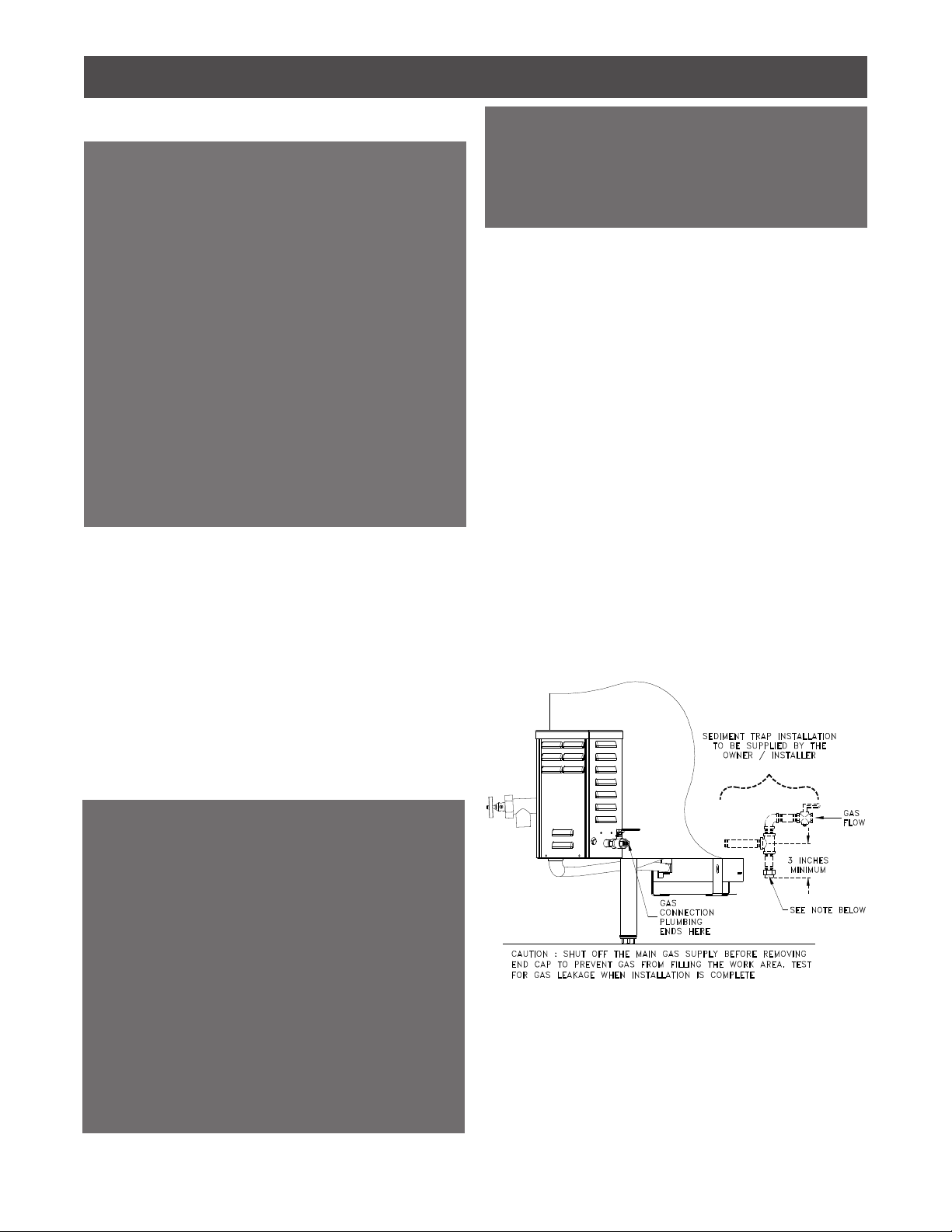
1. Shut o the main gas supply
before beginning the gas
connection.
2. Properly congure the gas
supply line to be used (see Fig.
1.2). The gas supply line must
be a minimum of 3/4” npt pipe.
It is your responsibility to ensure
that the supply line installed
is large enough to achieve
the proper pressure and allow
the required volume of gas to
ow. A sediment trap must
be installed to protect against
contamination of the ignition
system control. Install a manual
shut-o valve between the gas
supply line and the sediment
trap to allow for maintenance of
the trap.
Fig. 1.2 Conguration of Gas Connection
3. In making the connections, use a good quality joint
compound. If LP gas is supplied, a joint compound
resistant to LP gas should be used. Connect the supply
line to the ball valve at the rear of the unit. Tighten the
connection securely.
Electrical Connection
A power cord is provided on the back of the unit, for
connecting to the electric power supply. The installer
should verify the electrical requirements of the unit to
make sure your power supply line is capable of powering
the equipment properly. This information is listed on the
unit’s nameplate.
Standard 120 Volt Model: Connect a 120-volt, 60 Hz,
single (1) phase power cord.
Optional 240 Volt Model: Connect a 240-volt, 60 Hz,
single (1) phase power cord.
Gas Connection
WARNING: Electrical Grounding Instructions
This appliance is equipped with a three-prong
(grounding) plug for your protection against shock
hazard and should be plugged directly into a properly
grounded three-prong receptacle. Do no cut or remove
the grounding plug from this plug.
AVERTISSEMENT: Mise à la terre
Cet appareil est pourvu d’une che à trois broches
dont une mise à la terre assurant une protection contre
les chocs électriques. La prise dans laquelle elle esst
branchée doit être correctement mise à la terre. Ne pas
couper ni enlever la broche de mise à la terre de la che.
Also, it is required that an electrical cut-o device,
such as a fused disconnect switch or equivalent, be
installed in the power supply line between the main
power supply and the unit.
The pilot ame on this equipment is lit automatically
and requires electrical power to operate. The unit will not
operate if the power is o.
one gas type to the other.
It is your responsibility to post, in a prominent
location, instructions to be followed in the event the
user smells gas. This information must be obtained
from your local gas supplier.
5

Section I: Installation
To check inlet pressure - with other equipment on
the same line turned on and turned o:
Check the inlet pressure with all equipment on the same
gas supply line turned on and turned o.
1. Shut o the gas supply and remove the cover panel of
the control console. Remove the inlet pressure tap and
connect the pressure gauge or manometer (See Fig. 1.4).
2. Turn the gas supply back on. Light the main burner.
Turning the primarythermostat dial above room
temperature lights the main burner.
3. Record the inlet pressure readings on the Installation
Checklist for Warranty Validation. Be sure to take readings
with other equipment on the same line turned on and
turned o.
4. Reverse the procedure in step 2 to turn o the main
burner and shut o the gas supply before disconnecting
the manometer or pressure gauge.
5. Replace the inlet pressure tap plug.
Important! Always shut o the gas supply at the manual
valve in the gas supply piping to the unit (or at the tank
for LP gas), before removing the inlet pressure tap plug to
connect or disconnect a pressure gauge or manometer.
Inlet Pressure Too High? If natural gas pressure exceeds
7” water column or LP gas pressure exceeds 14” water
column, then a pressure-regulating valve must be
installed in the gas supply line.
Inlet Pressure Too Low? If natural gas pressure is below
5” water column or LP gas pressure is below 12” water
column, then the installer must determine the problem.
Too much equipment may be on the same line or a larger
gas supply line may be required.
Inlet pressure must be correct before checking the outlet
pressure.
Fig. 1.3 Pressure Regulator Specication Pressures
(in Inches Water Column)
Gas Valve
Type
Type of
Gas
Nominal Inlet
Pressure Range
Factory Set
Nominal Out-
let Pressure
Adjustment
Setting Range
Intermittent
Pilot
Natural 5.0 - 7.0”w.c. 3.5”w.c. 3 - 5
LP 12.0 - 14.0”w.c. 9.0”w.c. 8 - 12
Checking For Gas Leaks
WARNING:
Do not permanently supply gas to the unit until the gas
lines have been pressure tested. Faulty operation and
even equipment damage will result if the gas supply falls
below requirements.
The equipment and its individual shut-o valve must be
disconnected from the gas supply piping system during
any pressure testing of that system at test pressures in
excess of 1/2 psi (3.5 kPA).
The equipment must be isolated from the gas supply
piping system by closing its individual manual shut-o
valve during any pressure testing of that system at test
pressures equal to or less than 1/2 psi (3.5 kPA).
1. Turn on the main gas supply. With burner o, douse
the pipe connections up stream of the ignition system
control with a rich soap and water solution. Bubbles
indicate a gas leak. If a leak is detected, tighten pipe
connections. Replace the part if the leak cannot be
stopped.
2. With main burner in operation, douse pipe joints
and control inlet and outlet with rich soap and water
solution. If another leak is detected, tighten joints and
pipe connections. Replace the part if the leak cannot be
stopped.
Gas Control - Pressure Verication
Using a pressure gauge or a manometer, the installer must
record the gas pressure at both the inlet and outlet of the
ignition system control—rst with all equipment on the
same gas line turned on, then with all equipment turned
o. These readings are necessary for your installation and
warranty records. Gas pressure input and output ratings
for your equipment are listed on the unit’s nameplate.
Acceptable pressure ranges are provided below. Do not
exceed these ratings. NOTE: Since outlet pressure is
dependent upon proper inlet pressure, inlet pressure must
be checked rst.
6

Section I: Installation
Completing the“Installation Checklist”
With all of the preceding installation steps completed, the
primary aspects of the installation have been completed.
This manual contains an Installation Checklist that must
be lled out to show that certain key elements of the
installation have been performed properly.
IMPORTANT! TheInstallation Checklistmust becompleted
for your warranty to be valid. Do not neglect this step.
Outlet Pressure Tap
Fig. 1.5 Outlet Pressure Tap
To check outlet pressure - with other equipment
on the same line turned on and turned o:
Check the outlet pressure with all equipment on the same
gas supply line turned on.
1. Be sure the ignition system control knob is in the
OFF position. Remove the outlet pressure tap plug and
connect the pressure gauge or manometer (See Fig. 1.5).
Turn the ignition system control knob to the ON position.
2. Turn the gas supply back on and light the main burner
by following Step 2 in the previous procedure for checking
the inlet pressure.
3. Record the outlet pressure readings by following Step 3
in the Check inlet pressure procedure for checking the
inlet pressure.
4. Turn OFF the main burner and shut o the gas supply
before disconnecting the manometer or pressure gauge
by reversing the procedure in Step 2 in the previous
procedure for checking the inlet pressure.
5. Replace the outlet pressure tap plug
6. Replace the cover panel of the control console and turn
the gas supply back on.
Important! Always shut o the gas supply at the manual
valve in the gas supply piping to the unit (or at the tank
for LP gas), before removing the outlet pressure tap plug
to connect or disconnect a pressure gauge or manometer.
Outlet pressure too high or too low? If the outlet pressure
is too high or too low, but the inlet pressure is nominal,
the outlet pressure can be adjusted by the installer using
the following procedure.
• Remove the pressure regulator adjustment cap screw.
Inlet Pressure
Tap
Fig. 1.4 Inlet Pressure Tap • Using a screwdriver, turn the inner adjustment screw
clockwise to increase pressure and counterclockwise to
decrease pressure to the infrared burners.
• When proper outlet pressure has been achieved,
replace the pressure regulator adjustment cap screw.
The unit will not operate properly if the cap screw is not
in place.
Proper outlet pressure cannot be achieved? If following
the above procedure fails to attain proper outlet pressure,
and the inlet pressure is nominal, then the ignition system
control needs to be replaced.
7

Section II: Startup & Operation
Warning:
Always disconnect power before cleaning (or servicing)
the unit.
The control console is not waterproof. Never spray the
control console, electrical controls, ignition system
controls, or connections with water. Clean these areas by
wiping them with a clean, damp cloth.
When cooking, never allow water or foodstu to come in
contact with any electrical components.
Before operating your equipment, it must be cleaned
thoroughly. Refer to section IV: Caring for Stainless Steel
for instructions.
Important! Disconnect all electrical power before
cleaning the unit.
Clean the unit thoroughly with a mild detergent
solution. Always“wipe”
around the control
console (never spray).
Never rinse control
consoles with a spray
hose or let water come
in contact with any
electrical and control
components.
For routine cleaning,
Accutemp’s optional
“Care Kit” accessories
help you thoroughly
clean all surfaces,
including the inside of
the lid and the inside
of the draw-o valve.
During washing, excess
water in the kettle may be drained away through the
draw-o using the optional drain hose attachment.
Use the “Care Kit” to clean hard to reach places like inside
the lid and inside the draw-o valve. Rinse and drain
away wastewater easily through the optional drain hose.
Take care when removing the draw-o valve for
cleaning. The draw-o hex bonnet nut and valve stem
are surprisingly heavy. Do not drop them, since this can
cause damage to the stem creating leaks. Also be sure
to remove all water from the kettle before removing the
draw-o valve.
1. Make sure the stem is in the open position.
2. Unscrew the hex bonnet nut.
3. Carefully remove the nut and stem assembly
Removing & Cleaning the Draw-O Valve:
Initial Cleaning
8

Section II: Startup & Operation
4. Thoroughly clean the body and tube using the draw-
o cleaner brush provided with the Legion Care Kit.
5. When through, rinse with clean water and re-assemble,
taking care not to over-tighten the draw-o. It is designed
to be hand-tightened only.
We’ve already started the unit up during installation. Now
we’ll examine all control functions, step by step, for a full
understanding.
IMPORTANT: After installation or service and prior to
operating the unit, make sure the following are done,
otherwise the unit will not operate.
Make sure the ignition system control knob is in the
ON position.
Make sure the main electrical power and the gas
supply to the unit have both been turned on.
Fig. 2.1 Control Panel Features
Rocker Switch (On - O). Energizes the unit for operation.
Primary Thermostat Dial (Temperature). Allows the user
to set the cooking temperature of the unit.
Unit Power On Indicator Light (Green). Illuminates upon
depressing the rocker switch to the ON position. This
indicates the unit has been energized.
Heater Power On Indicator Light (Red). Illuminates upon
turning the thermostat dial to show that the infrared
burners are operating. Note: If the temperature of the
unit is already above the set temperature, the red heater
power on light will not come on.
Low Water Indicator Light (Amber). It alerts the user that
the water level in the steam jacket has fallen below the
recommended operating level and that the low water
relay has been activated, turning o the burner as a
safety precaution until the low water condition has been
remedied (Refer to Section III, Service & Maintenance,
Item 4, Filling Steam Jacket). Once the water level has
been increased to normal working levels the low water
relay will reset and permit normal operation.
Control Functions Summary of Control Functions:
9

Section II: Startup & Operation
Tilt Switch (ALTLGB & ALTLGB-F only). Automatically shuts
o the kettle when tilted. Care should be taken when
tilting unit lled with hot product.
Shutting Down the Unit:
Normal (Routine) Shutdown. Turn the primary thermostat
dial to the lowest temperature setting and press the
rocker switch to OFF.
Complete System Shutdown. Perform normal shut down
as described above. Then, turn the ignition system control
knob (located inside the control console, clockwise to OFF.
Do not force the knob. The appliance will completely shut
o. To resume normal operation, turn the ignition system
control knob to the ON position and set the primary
thermostat dial to the desired temperature setting.
How to Start Cooking:
1. Press the rocker switch to ON position, turn the primary
thermostat clockwise to the desired temperature. This
will cause the red indicator light to come on, showing that
the burner is operating.
2. Close the lid to speed up the heating process.
3. Once the unit has cycled (the red indicator light goes
out), you can start cooking immediately. However, to
guarantee the most even, stable heat you may want to let
it cycle several times.
4. If a new temperature is desired during a cooking
operation, simply turn the thermostat to the new
setting. Again, allow several cycles to ensure proper heat
stabilization.
5. To shut down the unit, turn the thermostat dial to OFF
and press the rocker switch to OFF.
10

Section III: Service and Maintenance
This section covers the basics of servicing and maintaining
your equipment. A “Maintenance and Service Log” is
included in this manual for your use in recording all
maintenance and service performed.
IMPORTANT: Service must be done by a qualied
technician experienced with commercial gas and electric
cooking equipment. Use only OEM supplied parts.
Unauthorized or generic parts can cause bodily injury and
equipment damage. If the unit ever needs repair during
the warranty period, prior authorization is required. Also
refer to the sections of this manual entitled Service Calls
and also Important Warranty Information.
Servicing
Warning: Always disconnect the power supply and shut
o manual gas valve before cleaning or servicing.
Re-Calibrating Thermostats (Do Not Attempt)
IMPORTANT! If thermostat is defective or not working
properly, it must be replaced (without breaking the seal)
and returned to Accutemp. The warranty is voided if the
seal is broken or any attempt is made to recalibrate a
thermostat. See below for replacement instructions.
1. Disconnect the unit from its power supply.
2. Turn o the manual gas valve
at the rear of the unit.
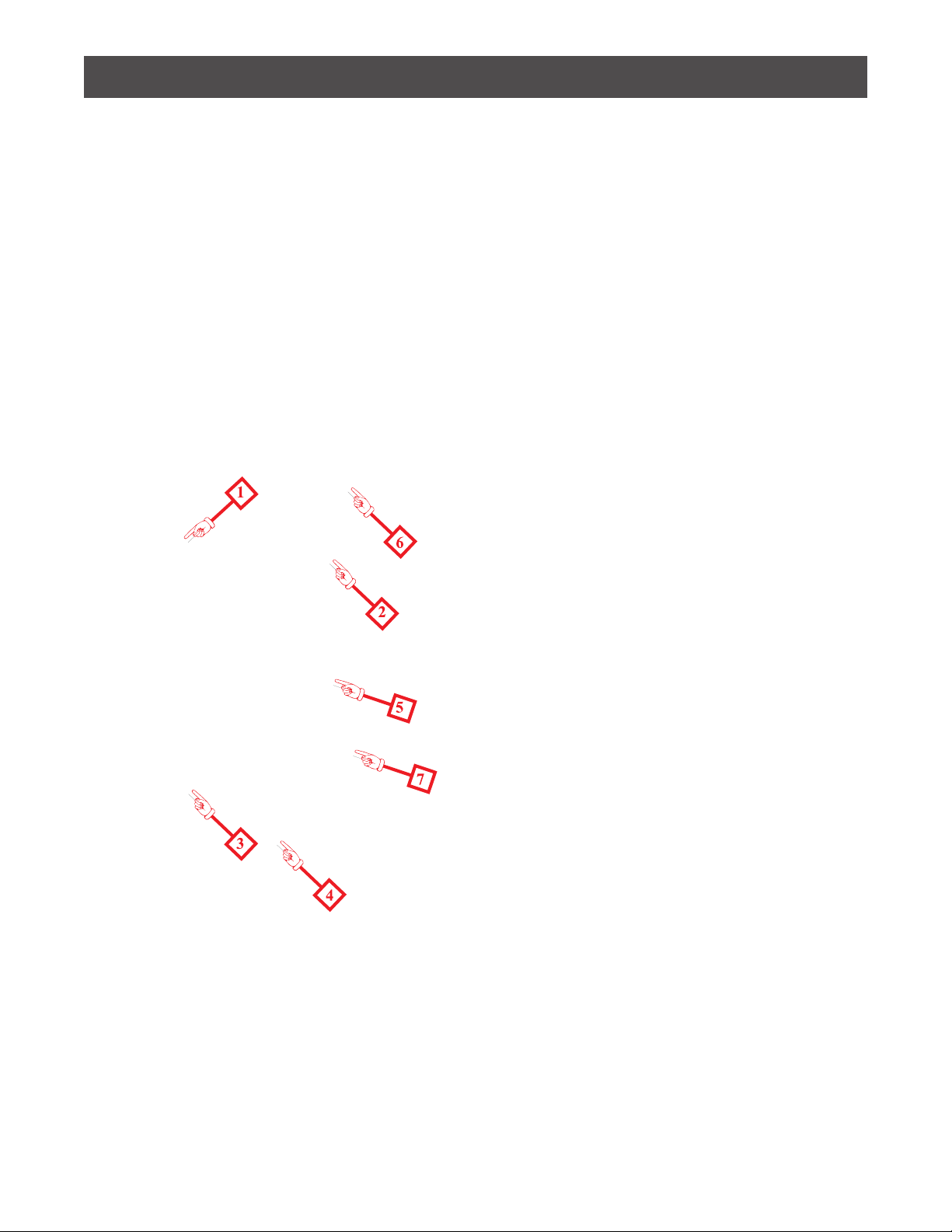
3. Remove the control
console panel.
4. On the existing primary
control thermostat control-
ler (Item 1), mark and dis-
connect the sensor (probe)
leads (Item 2) from terminal
1 and 2. For 120 VAC oper-
ation, mark and disconnect
the black wire(s) from termi-
nals 4 and 7 and white wire
from terminal 5. For 208 to
240 VAC operation, mark
and disconnect the black
wire(s) from terminals 3 and
7 and white wire from terminal 5. Mark and disconnect the
red wire from terminal 6. Mark and disconnect the black
wire from terminal 6.
5. If replacing the primary control thermostat controller
(Item 1), remove the knob on the front panel by loosening
the setscrew and loosen the rubber-coated nut to release
the controller from the front panel.
6. Reconnect the wires from the sensor (probe) leads to the
Replacing Primary Thermostat
11
Section III: Service and Maintenance
new controller and secure to front panel with mounting
nut and replace knob securing with setscrew.
7.Replace control console panel and secure in place.
8. If replacing the sensor (probe) (Item 2),drain water in
jacket below the sensor location.
9. Refer to step 4 to disconnect leads from primary con-
trol thermostat controller.
9. Remove sensor (Item 2) from kettle jacket using a
18mm deep well socket.
10. After installing new sensor, reconnect the wires from
the new sensor (probe) to the controller.
11. Replace control console panel and secure in place.
12. Rell kettle with pure distilled water. Refer to Fill-
ing Steam Jacket of this section for instructions.
B) Replacing the Ignition System Control
Disconnect power and turn o main gas supply before
starting.
To replace the gas control valve (Item 4);
1.Disconnect the controls connector and the igniter
connector from the gas control valve (Item 4).
2. Disconnect the pilot tube (Item 3) from the gas control
valve (Item 4).
3. Loosen exible gas hose nut (Item 7), using a crescent
wrench or 1 1/8 open end wrench, located under the
control console.
4. Remove the manual gas valve, reducing bushing and
nipple from gas control valve
5.Remove 1/4-20 bolts (Item 6) from rear of control
console to loosen bracket holding gas valve.
6.Remove gas control valve from control console.
Note: You may need to rotate valve slightly to allow
clearance for elbows and bracket attached to valve.
Make note of positioning of valve in control console when
removing to insure correct placement of new valve.
7.Reverse steps to secure new gas control valve in place.
12

Section III: Service and Maintenance
(C) Replacing the Gas Burner or Burner Orices
Refer to steps 1 through 3 of Replacing the Ignition
System Control then,
Remove 3 1/4-20 bolts from burner shroud (Item 8). Let
the shroud/gas burner assembly drop down, then pull
out from underneath the kettle.
Remove 3/8 nut and at washer located in center of
burner assembly (Item 9).
Lift burner out of shroud.
Reverse steps to replace new burner.
D) Replacing the Pilot/Igniter Assembly
Refer to steps in C) Replacing the Gas Burner or Burner
Orices then,
Turn gas burner over and loosen 2 1/4-20 bolts to remove
bracket from burner (Item 10).
Lift bracket away from burner and remove 1 slotted screw
from bracket which holds the igniter to the bracket.
Remove pilot tube using a 7/16 open end wrench (make
sure not to lose the orice inside the igniter).
Reverse steps to replace the new igniter.
13

Section III: Service and Maintenance
Actuator Maintenance and Adjustment
A) Actuator Tension Adjustment
The lid on the ALLGB and ALLGB-F(standard on 60 gallon
and up) can operate with spring-loaded actuators. If the
lid can be raised to any position, and it remains in that
position, the actuators are adjusted properly. Should the
tension need adjustment after shipping, or at any time
in the future, the following procedure can be performed.
Raise the unit’s lid completely. Removal of the stop nut
may be needed to raise the lid completely.
Remove the tube closure cap on the actuator. With a 3/4”
deep hex socket, turn the adjusting nut (located inside
the actuator sleeve) clockwise to increase the tension or
counterclockwise to decrease tension. Rotate the nut
one turn at a time and test the lid’s operation. When the
adjustment is complete, replace the tube closure cap on
the actuator sleeve.
B) Actuator: Re-Packing With Grease
The lid actuator(s) of your unit must be re-packed with
grease every six months to ensure proper operation.
Perform the following steps. Refer to Figure 3.1 and to
Figure 3.2.
1. Raise the lid of the unit fully.
2. Remove the tube closure cap.
3. Remove the self-locking 1/2-13 hex nut on the actuator
rod.
4. If the components inside the actuator sleeve do not
slide out easily, remove the bolt, which secures the
actuator sleeve to the frame lug. Put aside the bolt, nut,
and lock washer for re-assembly later.
5. Grasp the actuator sleeve and pull down away from the
actuator rod. The components inside the actuator sleeve
will slide out.
6. Pack the spring (or springs) with Bel-Ray No-Tox Clear
Grease #2. The grease must be liberally applied between
each coil.
7. After re-packing with grease, reassemble the
components back inside the actuator sleeve and slide the
sleeve back over the actuator rod.
8. Reconnect the actuator assembly to the frame lug
using the bolt, nut, and lock washer previously set aside.
9. Adjust the tension of the actuators using the procedure
described earlier in this section.
C) Actuator Replacement
Should the actuators on your unit ever require
replacement, use the following procedure. Refer to Figure
3.1 and to Figure 3.2.
1. Raise the lid of the unit fully.
2. Remove the tube closure cap.
3. Using a deep socket tool, loosen the self-locking hex
nut on the actuator rod (by turning it counterclockwise)
to eliminate pressure on the springs.
4. From the pivot arm of the actuator, remove the acorn
nut, bolt, lock washer, and spacer and retain them for
mounting the new actuator(s).
5. From the frame lug (at the other end of the actuator)
remove the acorn nut, bolt, and lock washer and retain
them for mounting the new actuator(s).
6. Mount the new actuators using the bolts, nuts, lock
washers, and spacers set-aside in the above steps.
Note: The actuator rod must be free to pivot during use.
Therefore, when tightening the hex bolt into the acorn
nut, tighten it completely, and then back o a half turn.
7.Afterthe newactuator(s)are installed,adjust thetension
using the procedure described earlier in this section.
14

Section III: Service and Maintenance
404486-001
404486-002
Parts List
TITLEPART NUMBER
QTY
ITEM
SLEEVE WELDMENT404483-00111
ACTUATOR ROD & LUG
455880
1
2
WASHER NYLON 1.355 X .5240850533
NYLON SHOULDER WASHER40850624
SPRING 8" X 1 1/4" X 5/8"
4085311
5
NUT SS LOCK 1/2-13
40559116
ACTUATOR END-CAP PLUG404485
17
ACTUATOR COVER STOP45669518
Parts List
TITLEPART NUMBER
QTY
ITEM
SLEEVE WELDMENT404483-00111
ROD ACTUATOR LUG45587912
WASHER NYLON 1.355 X .5240850533
NYLON SHOULDER WASHER40850624
NUT SS LOCK 1/2-13
40559116
SPRING 8" X 1 1/4" X 5/8"
40853115
ACTUATOR END-CAP PLUG404485
17
ACTUATOR COVER STOP45669518
346
17
5
8
283467404486-002 [60G - 150G INSULATED, & 80G -150G UN-INSULATED]
15
404486-001 [20G - 40G INSULATED, & 20G -60G UN-INSULATED]
2
Figure 3.1: Actuator Components & Assembly
Fig. 3.2: Removing/Installing Actuators
15

Section III: Service and Maintenance
Gas Control System
Fig. 3.3: SV9501 / 9502 Gas Control
When to Replace the Gas Control:
√ The gas control does not perform properly on checkout
or troubleshooting.
√ The gas control knob is hard to turn.
√ The gas control is likely to have operated more than
200,000 cycles.
√ The control is wet or looks as if it has been wet.
B) Adjusting the Pilot Flame
The pilot ame was adjusted at the factory. Should it ever
need adjusting, follow the instructions below.
Fig. 3.4: Pilot System for the SV9501/9502
SmartValve™ Gas Control
Proper Setting: The ame should envelope 3/8” to 1/2”
(10 mm to 13 mm) of the igniter sensor tip.
1. Turn o the thermostat dial.
2. Disconnect the lead to the MV terminal on the gas
control.
3. Re-light the pilot by turning up the thermostat to call
for heat.
4. Remove the pilot adjustment cover screw from the gas
control (see Fig. 3.3).
5. Turn the inner pilot adjustment screw clockwise to
decrease or counterclockwise to increase the pilot ame.
When done, replace the cover screw and tighten it rmly.
A). Maintenance of the Gas Control System
Your equipment came with an intermittent pilot gas
control system. The systems is as follows:
The SV9501/9502 SmartValve™ System Control combines
gas ow control and electronic intermittent pilot
sequencing functions into a single unit. The Q3450
SmartValve™ System pilot burner provides pilot ame
ignition and sensing for the SV9501/9502 Systems. It
consists of a replaceable igniter-ame rod assembly,
bracket assembly, pilot target, ground electrode, orice
assembly, compression tting and spring clip. The igniter
lights the pilot burner. The ame rod proves the pilot
ame and the pilot ame lights the main burner.
Control Knob Settings:
OFF. Prevents pilot and main gas ow through the
ignition system control.
ON. Permits gas ow into the control body and, under
control of the thermostat, to the pilot and main burners.
Frequency of Maintenance Required:
Cycling Frequency. Appliances that may cycle 20,000
times annually should be checked monthly.
Intermittent Use. Appliances that are used seasonally
should be checked before shutdown and again before
the next use.
Consequence of Unexpected Shutdown. Where the cost
of an unexpected shutdown would be high, the system
should be checked more often.
Dusty, Wet, or Corrosive Environment. Since these types
of environments can cause the gas control to deteriorate
more rapidly, the system should be checked more often.
16

Section III: Service and Maintenance
Filling Steam Jacket
Warning!
After start-up use pure, chloride free, distilled water only
(referred to as “water” in the following text). Do not use
tap water to rell to correct water level.
Appliance failure caused by incorrect water quality is not
covered under warranty.
Allow kettle to cool. Never attempt to add water to a hot
kettle.
Place the thermostat in the o position. Press the rocker
switch to the OFF position. Disconnect power at the
customer supplied electrical cut-o device.
Open the air vent by turning selector screw counter-
clockwise (See Fig. 3.6) until air blows through valve to
release any residual steam contained in the steam jacket
OR open the petcock by turning the lever to vertical (See
Fig. 3.7) to release any residual steam contained in the
steam jacket.
Remove sight glass and place a funnel in the inlet elbow.
Pour water into funnel. Continue adding water until the
Fig. 3.5: Examples of Problem Pilot Flames
C) Identifying Unsatisfactory Pilot Flames
Much can be determined by the appearance of the pilot.
The size, color, shape, sound, and movement of the ame
are all indicators. Refer to the chart below to identify and
correct possible problems.
water in the jacket is visible in the sight glass. DO NOT FILL
BEYOND THE TOP OF THE SIGHT GLASS LEVEL.
Remove funnel, replace sight glass in inlet elbow, securely
turn selector screw on Dole Air Valve clockwise as far as it
will go to return to automatic venting and restore power to
the kettle.
CAUTION: Drain the steam jacket if the kettle is to be stored
in an unheated area. Water freezing in the steam jacket
may cause damage to the unit. Drain is located behind the
control-housing panel.
Fig. 3.7: Filling Steam Jacket - Commercial Units
17

Section III: Service and Maintenance
Safety Relief Valve
Installation Instructions
This valve must be mounted in a vertical, upright position
directly to a clean, tapped opening located at the top of
the equipment. Under no circumstances should there be
a ow restriction or valve of any type between the safety
relief valve and the pressure vessel.
Be certain that all connections - including the valve inlet -
are clean and free from any foreign material.
Use pipe compound sparingly, or tape, on external
threads only.
The Btu/hr or lb/hr rating of the safety valve must equal
that of the equipment to which it is installed.
Warning! The safety relief valve may discharge large
amounts of steam and/or hot water during operation.
Therefore, a discharge line must be installed to reduce
the potential for bodily injury and property damage that:
√ is connected from the valve outlet with no obstructions
and directed downward to a safe point of discharge.
√ allows complete drainage of both the valve and the
discharge line.
√ is independently supported or securely anchored so as
to avoid applied stress on the valve.
√ is as short and straight as possible.
√ terminates freely to atmosphere when any discharge
will be clearly visible and is at no risk of freezing.
√ terminates with a plain end that is not threaded.
√ is constructed of a material suitable for exposure to
temperatures of 375° F or greater.
√ is of a pipe size equal to or greater than that of the valve
outlet over its entire length.
Do not cap, plug, or otherwise obstruct discharge pipe
outlet!
Operating Instructions
DO NOT ALLOW water to ow through a safety relief
valve as sediment or debris may be deposited on seating
surface if adding water to a kettle. Excessive deposits
may prevent the valve from operating properly and a
dangerous pressure buildup and equipment rupture may
result.
Maintenance and Testing
CAUTION! Make certain discharge pipe is properly
connected to valve outlet and arranged to contain and
safely dispose of boiler discharge before testing (see
“Installation Instructions”).
Under normal operating conditions a“try lever test” must
be performed every two months. Under severe service
conditions, or if corrosion and/or deposits are noticed
within the valve body, testing must be performed more
often. A“try lever test”must also be performed at the end
of any non-service period.
Test at or near maximum operating pressure by holding
the test lever fully open for at least 5 seconds to ush the
valve seat free of sediment and debris - then release lever
and permit the valve to snap shut.
If lift lever does not activate, or there is no evidence of
discharge, discontinue use of equipment immediately
and contact a licensed contractor or qualied service
personnel.
18
This manual suits for next models
3
Table of contents
Other AccuTemp Kettle manuals


