Table of Contents
UPGRADING YOUR COMPUTER............. 1
Installation precautions
..................1
ESD precautions
................................1
Required tools
......................................1
Pre-installation instructions
.....2
Post-installation instructions
..2
System Upgrade
....................................3
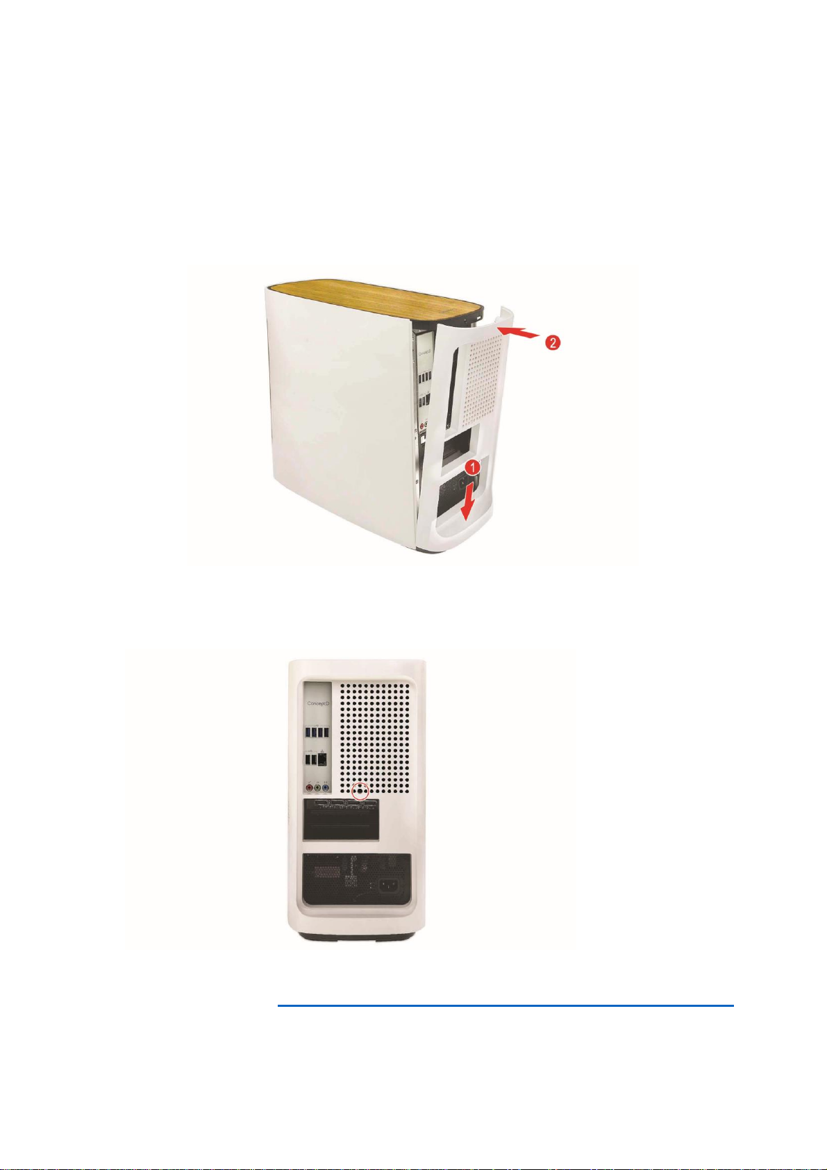
Removing the rear system
cover
............................................................3
Installing the rear system
cover
............................................................4
Removing the left side system
cover
............................................................5
Installing the left side system
cover
............................................................6
Hard drives
...............................................7
Removing the 3.5-inch hard
drives
...........................................................7
Installing the 3.5-inch hard
drives
...........................................................9
Memory
......................................................11
Memory configuration
guidelines
..............................................11
Removing a memory module
.12
Installing a memory module
...13
Graphic board
......................................14
Removing the Graphics board
........................................................................14
Installing the Graphics board
........................................................................16
M.2 SSD module
...................................18
Removing the M.2 SSD module
........................................................................18
Installing the M.2 SSD module
........................................................................20
CONCEPT D PALETTE............................. 23
ConceptD Palette Features
.........23
Monitoring.................................................24
Split Screen...............................................25
App Center ................................................26
Creative Tools Settings........................27