Acer S230HL User manual

A
CER_LCD_
_S230HL

L
A
CER_L
C
D_S230HL
_
Contents
Table of Contents
Important Safety
Notice-------------------------------------------------------------------------------------
01
01. Product Specification--------------------------------------------------------------------------------- 02
02. OS Menu----------------------------------------------------------------------------------------------- 17
03. Exploded
i
a
gram
------------------------------------------------------------------------------------- 21
04. Assembly and isassembly Procedures----------------------------------------------------------- 25
05.
Troubleshooting---------------------------------------------------------------------------------------- 44
06. Firmware Upgrade Procedure------------------------------------------------------------------------ 47
07. Writing E I Procedure------------------------------------------------------------------------------- 49
08. FRU (Field Replaceable Unit) List------------------------------------------------------------------- 52
09. Schematics and Layouts------------------------------------------------------------------------------ 54
Safety No
t
ice
Any person attempting to service this chassis must familiarize with the chassis and be
aware of the necessary safety precautions to be used when serving electronic equipment containing
high voltage
.

3
Important Safety No
ti
ce
ACER S2
30
HL 1
Go to contents page
Product Announcement:
This product is certificated to meet RoHS irective and Lead-Free produced definition. Using approved
critical components only is recommended when the situation to replace defective parts. Vender assumes
no liability express or implied, arising out of any unauthorized modification of design or replacing non-
RoHS parts. Service providers assume all liability.
Qualified Repairability:
Proper service and repair is important to the safe, reliable operation of all series products. The service
providers recommended by vender should being aware of notices listed in this service manual in order
to minimize the risk of personal injury when perform service procedures. Furthermore, the possible
existed improper repairing method may damage equipment or products. It is recommended that service
engineers should have repairing knowledge, experience, as well as appropriate product training per
new model before performing the service procedures.
NOTICE:
! To avoid electrical shocks, the products should be connect to an authorized power cord, and turn off
the master power switch each time before removing the AC power cord.
! To prevent the product away from water or explosed in extremely high humility environment.
! To ensure the continued reliability of this product, use only original manufacturer’s specified parts.
! To ensure following safety repairing behavior, put the replaced part on the components side of PWBA,
not solder side.
! To ensure using a proper screwdriver, follow the torque and force listed in assembly and
disassembly procedures to screw and unscrew screws.
! Using Lead-Free solder to well mounted the parts.
! The fusion point of Lead-Free solder requested in the degree of 220°C.

2 ACER S2
30
HL
Go to contents page
1. Product Specification
1.1 Scope:
This document defines the design and performance requirements for the 23” wide flat panel monitor. The display
element shall be a 23” inch diagonal, Full H (1920 x 1080) resolution TFT-LC display (Thin Film Transistor
Liquid Crystal isplay) and support 60Hz.Video input signals are one Analog -sub and one VI with non-
interlaced signal. Power saving function complies with the VESA PMS ( isplay Power Management Standard).
General display parameters:
Optical Characteristics:
1.2 General Requirements:
1.2.1 Test Condition:
Normal test condition is that brightness level set at Max. and contrast level set default. Test pattern is full
white pattern. The warm up time is more than 30 minutes. Ambient light should be less than 1 Lux.
1.2.2 Test Equipment:
The reference signal source is a calibrated Chroma 2326 or Quantum 801G video generator. The use of
compatible generators during qualification and production is acceptable. Luminance meter is Minolta CA210,
TOPCON BM7 or compatible equipment.

1. Product Specification
ACER S2
30
HL 3
Go to contents page
1.3 Electrical:
This section describes the electrical requirement of the pure A and A+ monitor. Below is the pure A monitor’s block
diagram.
.
And, below is A+ monitor’s block diagram.

4 ACER S2
30
HL
Go to contents page
1. Product Specification
This LC monitor includes an interface board, power adaptor and a function key board. The interface board controls
the TFT panel control logic, brightness control logic, and C- C conversion to supply the appropriate power to the
whole board and LC panel then transmitting LV S signals into LC Module to drive the LC display circuit. The
power adaptor will provide the C power to the interface board and LC panel. The function key board is used for
OS control, monitor power ON/OFF and the LE indicator for power status.
ITEM
SPEC
F
r
equen cy Ra nge
s
H 30kHz ~ 83kHz, V 56Hz ~ 75Hz
Max Pixel
c
l
o
ck
173MHz
RGB Inp ut Le
v
e
l
0.7Vp-p
RGB Inp ut Impedan
c
e
75
Ω
Sync Inpu t Signal
Separate SYNC,
Ana
l
o g S
i
gna l Input
Sync Inpu t Impedan
c
e
2.2K
Ω
F
r
equen cy Ra nge
s
H 30kHz ~ 83kHz, V 56Hz ~ 75Hz
Max Pixel
c
l
o
ck
165MHz
Input Le
v
e
l
150mV<=Vp-p<=1560mV
Input Impe dan
c
e
100
Ω
VI ( igital Video Interface)
H CP
H CP 1.0
C Jack ( power adaptor)
19V, 2.1A,
Conne
c
to
r
s
Input
c
onne
c
to
r
s
-SUB 15 pin , VI 24pin
AC IN 90~26 4V No
r
m al Op eration
30W Ma
x
Power Sa
v
i
ng
< 0.6 W @ (110VAC) / < 0.7 W @ (220VAC)
Power Co n
s
ump
ti
on
Power Off
< 0.53W @ (110VAC) / < 0.63 W @ (220VAC)
User’s Co ntrol
Front Panel Bu tton
s
POWER, Right, Left, M ENU, AUTO,E
imm
i
n g control range(max-min/max) x 100%
100%
Preset T
i
m ing
29
Pre- efined Timing
User’s Timing
9
Plug and P
l
a
y
VESA C2B
Power Sa
v
i
ng
PMS

4 ACER S2
30
HL
1. Product Specification
ACER S2
30
HL 5
1.3.1 Interface Connectors:
1.3.1.1 C J ack, Power Adaptor:
The AC inlet connector shall be an IEC/CEE-22 type male power receptacle for connection to mains power. The
power cord shall be black with length of 1.5±0.05 meters. The power cord type is different from regions.
1.3.1.2 Analog Connector and Cable: The analog signal cable shall be black and 1800 mini-meters. The analog VGA cable
shall be a molded-over, shielded, triple row, 15 pins and blue color type connector.
A .
-
S U B
Pin
Signal escript ion Pin
Signal escript ion
1
Red Video Red video signal input 9
+5V +5V from host system
2
Green Video
Green video signal input 10
CC-GN
Ground for signal
3
Blue Video Blue video signal input 11
N.C No connection
4
Ground Ground 12
S A I2C S A for VESA C2B
5
VGA etect VGA connection detection 13
H Sync Horizontal sync signal
6
Red Gnd Ground for Red video 14
V Sync Vertical sync signal
7
Green Gnd Ground for Green video 15
SCL I2C SCL for VESA C2B
8
Blue Gnd Ground for Blue video
B. Key Board connector
Key Board
co
nnector: J1
Pin
Signal escript ion Pin
Signal escript ion
1
Key1 A C1 5
LE _CONN LE blue control
2
Key2 A C2 6
GN Ground
3
PWR_KEY Power On/Off control 7
3V3 _REG 3.3V supply power
4
NC No connection
C. Backlight connector
Backlight connector BJ1
Pin
Signal escript ion Pin
Signal escript ion
1
LE _ST2 6
V _LE RV
2
NC No connection 7
NC No connection
3
NC No connection 8
NC No connection
4
NC No connection 9
NC No connection
5
V _LE RV
10
LE _ST1
. VI connector
Pin
Signal escript ion Pin
Signal escript ion
1
CH2- TM S negative input of CH2
13
NC No connection
2
CH2+ TM S positive input of CH2
14
Power +5V
3
Logic Ground Ground 15
Plug etect etect cable plug in
4
NC No connection 16
Sense pin Sense pin/ pull high
5
NC No connection 17
CH0- TM S negative input of CH0
6
C2B SCL I2C SCL for VESA C2B 18
CH0+ TM S positive input of CH0
7
C2B S A I2C S A for VESA C2B 19
Logic Ground Ground
8
NC No connection 20
NC No connection
9
CH1- TM S negative input of CH1
21
NC No connection
10
CH1+ TM S positive input of CH1
22
Logic Ground Ground
11
Logic Ground Ground 23
CLK+ TM S positive input of Clock
12
NC No connection 24
CLK- TM S negative input of clock
Go to contents page

6 ACER S2
30
HL
Go to contents page
1. Product Specification
ACER S2
30
HL 5
E. Flat Panel Connector
a. Input signal connector of mini-LV S
Pin
Signal escript ion Pin
Signal escript ion
1 GN Ground 26
VCOMC VCOMC Voltage
2 LV5- Mini LV S Receiver Signal(5-) 27
VCOMC VCOMC Voltage
3 LV5+ Mini LV S Receiver Signal(5+) 28
VCOM VCOMC Voltage
4 LV4- Mini LV S Receiver Signal(4-) 29
VCOM VCOMC Voltage
5 LV4+ Mini LV S Receiver Signal(4+) 30
VCC Logic Voltage
6 LV3- Mini LV S Receiver Signal(3-) 31
VCC Logic Voltage
7 LV3+ Mini LV S Receiver Signal(3+) 32
V Panel riving Voltage
8 GN Ground 33
V Panel riving Voltage
9 LVCLK- Mini LV S Receiver Clock Signal- 34
V Panel riving Voltage
10
LVCLK+ Mini LV S Receiver Clock Signal+ 35
VGH Gate High Voltage
11
GN Ground 36
VGH Gate High Voltage
12
LC2- Mini LV S Receiver Signal(2-) 37
VGL VGL voltage
13
LV2 Mini LV S Receiver Signal(2+) 38
VGL VGL voltage
14
LV1- Mini LV S Receiver Signal(1-) 39
G_RES GIP Reset Pulse
15
LV1+ Mini LV S Receiver Signal(1+) 40
GV _E GIP Panel V for Even Gate TFT
16
LV0- Mini LV S Receiver Signal(0-) 41
GV _O GIP Panel V for Odd Gate TFT
17
LV0+ Mini LV S Receiver Signal(0+) 42
CLK4 GIP GATE Clock4
18
GN Ground 43
CLK4 GIP GATE Clock4
19
SOE Source Output Enable SIGNAL 44
CLK3 GIP GATE Clock3
20
POL2 Polarity Control Signal 45
CLK3 GIP GATE Clock3
21
POL Polarity Control Signal 46
CLK2 GIP GATE Clock2
22
CSC Charge Share mode control Signal 47
CLK2 GIP GATE Clock2
23
H2 OT Horizontal 2 Inversion Sognal 48
CLK1 GIP GATE Clock1
24
ICLK_REST Vertical Start Plus 49
CLK1 GIP GATE Clock1
25
GN Ground 50
GN Ground
b. Input signal connector of LE Backlight power
Pin
Signal
escript ion Pin
Signal escript ion
1
FB1 Channel1 current Feed Back 6
Vled LE Power supply (common Input)
2
NC No connection 7
NC No connection
3
NC No connection 8
NC No connection
4
NC No connection 9
NC No connection
5
Vled LE Power supply (common Input)
10
FB2 Channel2 current Feed Back
1.3.2 Input Signals:
Video Input Signals Range(Analog RGB Signal)
No.
Sym bol
Item
M in
Max
Unit
Remark
1
Fh
Ho rizontal Frequency
30
83
kHz
Min imum range
2
Fv
Vertical Frequency
50
75
Hz
Min imum range
3
Fclk
Pixel Clock Freque ncy
173
MHz
4
Vih
Hi Le vel I nput
2
5
V
No te 1)
5
Vil
Low Level In put
0
0.8
V
No te 1)
6
Vid eo
RGB Analo g Video Level
0
0.735
V
75
Ω
to Ground
Note 1) 2.2k
Ω
to Ground. Schmitt-Triggers Input. Support 3.3V H & V SYN Output device.
1.3.2.1 Video Signal Amplitudes:
The video inputs consist of Red, Green and Blue signals each has its own coaxial cable terminated at the
monitor. These video signals are analog levels, where 0V corresponds to black, and 735mV is the
maximum signal amplitude for the respective color. The video signal is terminated with 75 ohms.

6 ACER S2
30
HL
1. Product Specification
ACER S2
30
HL 7
1.3.2.1 Video Signal Amplitudes:
The video inputs consist of Red, Green and Blue signals each has its own coaxial cable terminated at the
monitor. These video signals are analog levels, where 0V corresponds to black, and 735mV is the
maximum signal amplitude for the respective color. The video signal is terminated with 75 ohms.
1.3.2.2 Video Signal Termination Impedance:
The analog video signal termination shall be 75 ohm +/- 2%.
1.3.2.3 Synchronization (Sync) Signals:
The Horizontal Sync (HS) TTL signal is used to initiate the display of a horizontal line. HS may be either
active high or active low according to the timing. The Vertical Sync (VS) TTL signal is used to initiate the
display of a new frame. VS may be either active high or active low according to the timing.
1.3.2.4 Sync Signal Levels:
The monitor must accept sync signals from both 3.3 and 5 volt TTL logic families. The inputs shall sense a
logic 0 when the input is 0.8 volt or less and shall sense a logic 1 when the input is 2.0 volts or greater. In
addition to these level requirements, there shall also be a minimum of 0.3 volt hysteresis provided for noise
immunity (typically by using a Schmitt Trigger input). That is, the input level at which the monitor actually
detects a logic 0 shall be at least 0.3 volt lower than the level at which it actually detects a logic 1. If the
monitor sync processing circuits were designed with 3.3 volt logic family, then the sync inputs must be 5
volt tolerant.
1.3.2.5 Sync Signal Loading:
TTL input loading shall be equivalent to one TTL input load. When logic 0 is asserted by a sync input, the
maximum current source from any single monitor sync input to the driver is 1.6 mA. When logic 1 is
asserted, the maximum current source from the driver to any single monitor sync input is 400 uA.
1.3.2.6 Abnormal Signal Immunity:
The monitor shall not be damaged by improper sync timing, pulse duration, absence of sync, abnormal
input signal amplitude, or any other anomalous behavior of a graphics card.
1.3.2.7 igital TM S Input ( VI signal input):
These video inputs consist of TX0+/- to TX2+/- and CLK+/- signals, each with its own shielded twisted
pair. These video signals are digital levels. Each signal pair is terminated by a normal 100 ohms.
1.3.3 User Controls and Indicators:
1.3.3.1 Power On/Off Switch:
The monitor shall have a power control switch visible and accessible on the front of monitor.
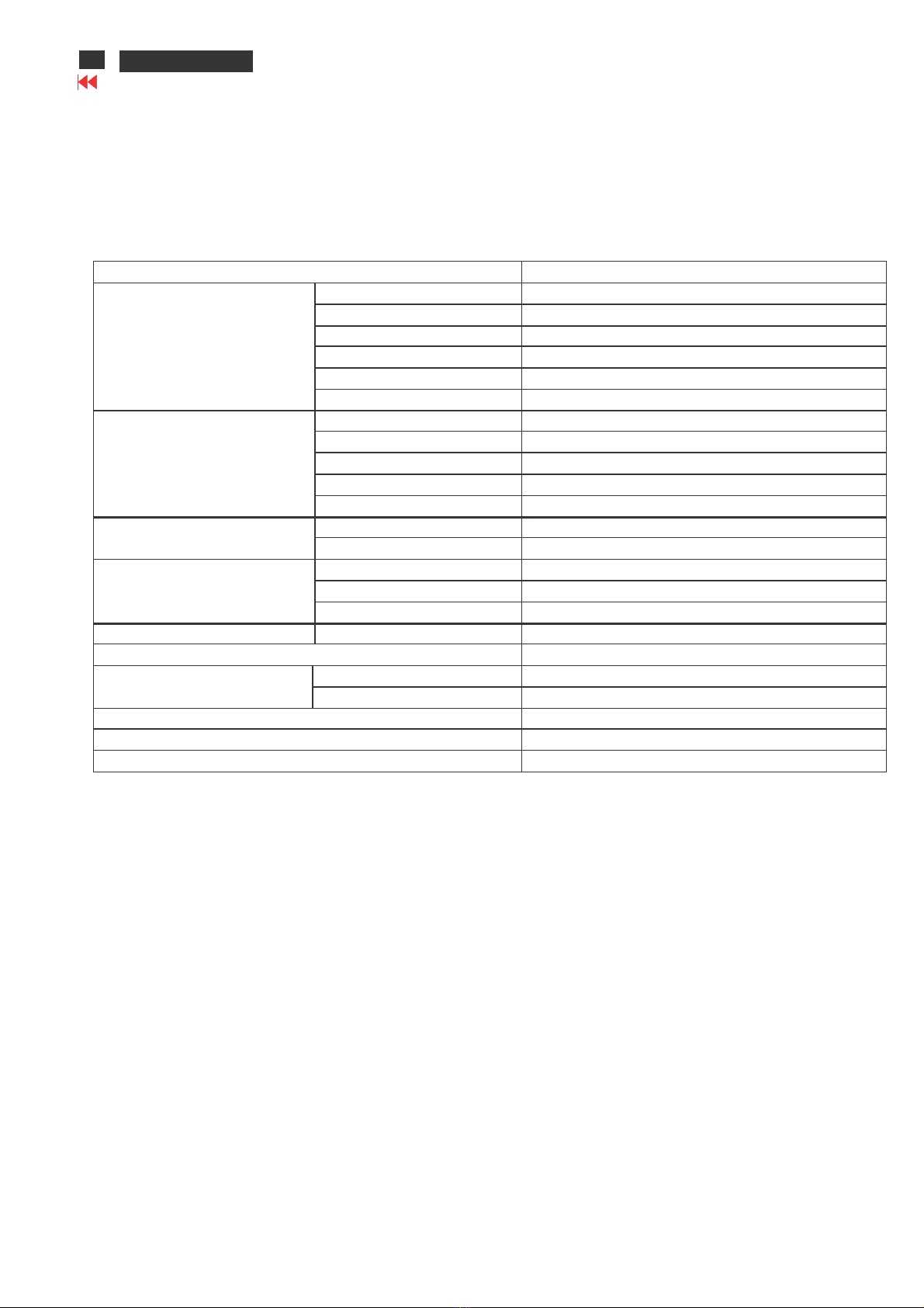
1.3.3.2 Power Indicator LE :
The monitor shall have LE indicators located on the front of the monitor. Table 1 is the LE color for the
power indicator.
LED light Status Remark
Off Power off
Blue Power on Signal is alive
Blinking Blue Standby/power saving No signal
Go to contents page

ACER
S230HL
8
1. Product Specification
ACER S230HL
Go to contents page
1.3.3.3 On-Screen isplay:
O Scree Display system shall be used to co trol the mo itor. Curre t setti g will be saved a d OSD
will be tuned off when the keys are not touched for a period of time.
A) Key Function Overview:
All functions are controlled by OS buttons on the front of front bezel.
Buttons Names escription
1 E Key Press “E key” button to show the first menu. Press this button
again to select different preset display scenarios.
2 Auto/Exit
As the input source is -Sub, press this key to activate the Auto
function.
Press this key to exit OS .
3 Menu/Enter Press MENU button to activate the first menu. Press this button
again to enter the main menu
4 Select "-" This button allows the user to move up between OS items and
decrease the value of sliding bar.
5 Select "+" This button allows the user to move down between OS items
and increase the value of sliding bar
6 Power
After AC on by plugging in a power cord and pressing Power
button, LE indicator turns to blue to indicate power on. To turn
off this device, press this button again
B) Menu Operation:
Pressing the MENU button brings up the first level menu. This menu button is used to enter the second
OS menu also.
1
s t
Sub
Menu
2
nd
S
ub
Menu
3
r d
Sub
Menu
4
r d
Sub
Menu
V
alue
VGA
Acer
Color
managem
ent
v
Brightnes
s
Slider
[100]
0-100
/
1
v
Contrast
Slider
[50] 0-100
/
1
v
H. Po
sition
Slider
50-10 0
/
1
v
V.
Positi on
Slider
50-10 0
/
1
v
Focus
Slider
[50] 0-100
/
1
v
Clock
Slider
[50] 0-100
/
1
v
Cold
93
00K
[W arm
]
65
00K
Red
0-100
Green
0-100
Color
Temp
Us er
Blue
0-100
v
Picture
Auto Co
nfig
v
OS
OS
Timeout
[10]10
-120
v
Full
v
Wide
Mode
A
spect
v
C/CI
On
/Off
v
A
CM
On
/Off
v
Input
VGA
v
(E
MEA)
English,
Russian,
French ,
Spanish,
G
erman
,Italian,
utch,
Turkish
Polish,
P
ortug
uese
F
i
nn
i
s
h
Russia
Settin
g
Language
(NON
E
MEA)
English,
French
Spanish,
G
erma
ny
Italian, T
Chinese,
S
Chinese,
Japan
v
Reset
v
In
forma
tion
Resolution
H/V
frequ
ency
X
XXX
input
Serial
num
ber.
v

8 ACER S2
30
HL ACER S2
30
HL 9
Go to connects page
S
1. Product Specification
C) OS Function:
No Signal
This func
ti
on gives a
war
ning message when
sel
ected input signal is
not
active. When
the
Monitor detected that the VGA or VI is s us pend or standby mode.
The
Monitor shall display a
message,
“
No Signal ” for 3 seconds and the
LE
s hall be blue, and to alert the user that
input
sinal
i
s not active. Then the monitor shall go into sleep mode and
the
LE
shal
l be Blinked
.
Input not support
This func
ti
on gives warning message about input
r
esolution or
refresh
rate that the monitor
cannot support. When an input
si
gnal
w
hich
is
out of the normal
oper
ation
r
ange defined in
Section 1.3.4.2 Then
the
monitor will display
“
Input not supported” mess
age:
1. Pixel
cl
ock frequency : 173MHz
2. V-sync
fr
equency:55Hz
>
FV
> 7
5Hz
3. H- sync frequency: 30KHz > F H >
80KH
z
Cable not
connect
T
h
i
s
f
u
n
c
t
i
o
n
g
i
v
e
s
w
a
r
n
i
n
g
m
e
ss
a
g
e
w
he
n
t
h
e
V
G
A
c
a
b
l
e
i
s
n
o
t
c
o
nn
e
c
t
ed
.
W
h
e
n
t
h
e
M
o
n
i
t
o
r
detected that the VGA c able is not connected to the monitor . The
OS
shall di splay a message
“
Cable not connected” al l the
ti
me to alert
the
user that the video
cabl
e
i
s not plugged in. The LE
shall be blue.
The
monitor shall use a method of a pull -up resistor on a ground pin
to
determine
i
f the video cable is connected to the
PC.
) OS Control Factory efault Values:
The OS controls shall have the following factory default values:
Brightness: 100 Contrast: 50
Color Temperature: Warm(6500)/Cool(9300)/User (R/G/B all are 100)
Horizontal Position of Screen: Hor.: 50, Ver.: 50
OS Timeout: 10 seconds
OS Language: English
1.3.4 Monitor Modes and Timing Capability:
1.3.4.1 Format and Timing:
The monitor shall synchronize with any vertical frequency from 50 to 75 Hz, and with any horizontal
frequency from 30 to 83 KHz for analog input and VI input. If the input frequency is beyond the specified
range, the monitor shall display a warning screen indicating that the input frequency is out of range.
Under no circumstances shall any combination of input signals cause any damage to the monitor.
1.3.4.2 Factory Assigned isplay Modes:
There are 25 factory pre-set video modes. Pre-defined mode parameters will be recalled if the operating
mode is one of those pre-set modes. If the operating mode is not one of those stored in memory, the
monitor CPU will select the PRESET timing for a mode that is the next lowest in horizontal scanning
frequency The screen parameters can be adjusted by the front bezel control buttons and then saved as a
user defined mode. The monitor shall include all the preset video timings shown in the following table.

10
ACER S2
30
HL
1. Product Specification
ACER S2
30
HL 9
Go to contents page
1.3.5 Controller Requirements:
1.3.5.1 General Requirements:
The monitor shall include a controller which is capable of converting the analog RGB signal or VI
digital signal to the panel. The controller will include a PLL, A/ converters, TM S receiver and other
circuitry necessary to perform its function. The PLL shall be stable enough to ensure a stable image.
1.3.5.2 Video Stretching:
The monitor shall have the function to “stretch” the video signal, so that an input signal from the
computer in any resolution smaller than 1920x1080 is automatically expanded to fill the entire
screen.
1.3.5.3 Panel Timing and Interface:
The controller supplied with the monitor shall control all panel timing. This controller shall adequately
insulate the monitor from the computer, so that no possible combination of input signals from the
computer shall cause damage to the flat panel or any other component of the monitor.
1.3.6 Power Adaptor Requirements:
The AC to C power adaptor for this monitor shall be a C power supply. This power adaptor shall have an IEC
receptacle for mains power input and provide sufficient power for backlight assembly
,
interface board and panel. And it
should meet all requirements specified in following Table.
AC TO C Converter
Requirement
Input Voltag
e
Ra
nge
The opera ting range shall be from 90 to 264 VAC sinusoidal for all
models
specified.
Input
Frequency
Range
Input power frequency range shall be
f
rom 47 to
63Hz.
Power
Consumption
Power consumption for the monitor shall be less than 30 W over the
specified
voltage and frequency ranges.
In
power off mode the power consumption will be less than 0.6W
(at
11
0VAC).
Lin e
Fuse
The AC input shall be fused and become electrically open as a result on
an
unsafe current level. The fuse
may
not user
replaceable.
Initial
Cold
Start
The power adaptor shall start and function properly when under full load,
with
worst case conditions of in
put
voltage, input frequency, operating
tem
perature, and cold backlight LE
.
Inrush
Current
The inrush current must be limited to when operated at 120VAC,
a
nd when operated at . Inrush current is
measured at an
ambient
temperature of 25°C, with the unit temperature stabilized in the power
off.
Hot
Start
Cycle
The power adaptor shall not be damaged when power ON for one second
and
OFF for one second for
seven
consecu
tive times after opera ting for one hour at full load, 25°C, and nom
inal
input line
voltage.
Under
Voltage
The power adaptor shall contain protection circuitry such that the application
of
an
input voltage below
the
minimum specified in this table shall no t cause damage to the power
adaptor
unit
nor cause failure of the inp
ut.
Line Tran
sient
The power adaptor shall operate within EN 61000-4-4 (+/-1KV) and EN
61000-4-5(+/-2KV).
The power adaptor shall operate and comply with CE
mark.
1.3.7 isplay Communications Channel:
The monitor shall provide a display communications channel that conforms to VESA C2B
hardware requirements. This configuration shall contain the 128-byte E I file as specified by
VESA E-E I Standard. Once the E I is programmed the write protection function will enabled.
So the EEPROM data cannot be overwritten.

1. Product Specification
ACER S230HL 11
Go to contents page
1.4 Flat Panel:
1.4.1 General Requirements:
The panel shall be a FULL H resolution 23” diagonal TFT-LC
1.4.2 Panel Timings:
The controller in the monitor shall translate video timings from the PC to meet the timing requirements listed in
Panel specification. Under no circumstances may the controller supply the panel with timings that may result
in damage. The controller shall insulate the panel from the PC, so that the panel shall always be driven
according to its specification regardless of the timings being sent from the PC.
1.4.3 Polarizer Hardness:
The outer face of the front polarizer panel shall be covered with a coating with a 3H hardness value.
1.4.4 Backlight Requirements:
1.4.4.1 General Requirements:
The LE shall have a continuous operating life of at least 30000 hours at 25°C. The operating life is
defined as having ended when the illumination of light has reached 50% of the initial value. The
LE shall extend a sufficient amount from the edge of the light guide that sputtering over the life of
the lamps shall not cause degradation of the luminance uniformity (such as non-illuminated bands
along the edges of the display).
1.4.5 efects:
1.4.5.1 Visual Inspection:
The LC panel shall be inspected with all pixels set to white, black, red, green and blue. The color
variation, brightness variation, and overall appearance must meet the SPEC.
1.4.5.2 isplay egradation:
Over the life of the product, variation of the parameters specified in Panel specification shall be
maintained within reasonable limits. The panel must not exhibit any significant defects while in
operation . This does not in any way change the warranty given by the panel manufacturer.
1.4.5.3 Light Leakage:
Except for the active display area, there shall be no light emission visible from any angle from any
other part of the display. For this test, the ambient illumination will follow the panel specification 300
to 700 lux.
1.4.5.4 Allowable efects:
No cosmetic defects are allowed except those specified below. The conditions of visual inspections
are as follows:
- Viewing distance: 35~50cm.
- Ambient illumination: 300 to 700 lux.
- Viewing angle range shall be 170 degrees Horizontal and 160 degrees vertical typically.

12 ACER S230HL
1. Product Specification
Go to contents page
- efects not apparent within one minute shall be ignored.
1.4.5.5 efect Terminology:
ark Spots / Lines: Spots or lines that appear dark in the display patterns and are usually the result
of contamination. efects do not vary in size or intensity (contrast) when contrast voltage is varied.
Contrast variation can be achieved through the use of varying gray shade patterns.
Bright Spots / Lines: Spots or lines that appears light in the display patterns. efects do not vary in
size or intensity (contrast) when contrast voltage is varied. Contrast variation can be achieved
through the use of varying gray shade patterns.
Polarizer Scratch: When the unit lights, lines appear light (white) with display patterns dark and do
not vary in size. Physical damage to the polarizer does not damage the glass.
Polarizer ent: When the unit lights, spots appear light (white) with display patterns dark and do not
vary in size. Physical damage to the polarizer does not damage the glass.
Bright/ ark ot: A sub - pixel (R, G, B dot) stuck off / on (electrical).
1.4.5.6 LC Inspection method:
*Ambie t co ditio s:
*Viewi g dista ce:
The distance between the LCM and the inspector eyes shall be at least 35~50cm
Dot Defect:

ACER S230HL 13
Go to contents page
1. Product Specification
Polarizer Defects:

1. Product Specification
ACER S230HL 14
Go to contents page
1.5 Optical Characteristics:
1.5.1 Brightness uniformity:
The uniformity is determined by using a photometer (CA-210) to measure the 9 points luminance in front of
monitor after at least 30 minutes warm up. It shall be test at 1920x1080/60Hz mode and full white square
pattern with contrast / brightness in default value. The values specified are at an approximate distance 50 cm
from the LC surface and at 0 viewing angle.
The 9 test points are defined as below:
The variation in surface luminance , δW is defined as
Minimum (P1,P2 …..P9)
δW = --------------------------------------------- *100
Maximum (P1,P2 …..P9)
δW
= 75% Mi n
Remark: The black luminance non-uniformity are no defined by panel spec, therefore, we don't define the
spec. for black luminance non-uniformity.
1.5.2 Contrast ratio (CR):
1.5.2.1 General CR:
The contrast ratio is determined by using a photometer (CA-210) to measure the maximum and
minimum luminance in front of monitor after at least 30 minutes warm up. It shall be test at
1920x1080/60Hz mode and full white/full black square pattern with contrast/brightness in default
value. The values specified are at an approximate distance 50cm from the LC surface and at 0
viewing angle. The contrast ratio is calculated as below:
Max. Surface luminance with all white pixels
Contrast ratio (CR) = -----------------------------------------------------------------
Max. Surface luminance with all black pixels
CR = 1000:1 typ. (typ)
1.5.2.2 ACM (Auto Contrast Management):
The input image signal source may be various levels of illumination, and this ACM unit can analyze it
as histogram for the various levels of illumination, according to the analyzed result, when input a low-
luminance level image, display brightness will be adopted to corresponding low level, so that enhance
the contrast rate, this facilitates visual ergonomics enhancement .The monitor should me CR
>12000000:1 when ACM function is active.

15 ACER S230HL
1. Product Specification
Go to contents page
1.5.3 Response time:
The response time is defined as below:
Tr + Tf : 5 msec typ.
Remark: Optical response time vs gray scale.Test condition: brightness set to max, and contrast set to default.
1.5.4 Viewing angles:
The viewing angles are measured at CR >=10 as below :
Horizontal Left: 85 degrees typ.; Right: 85 degrees typ.
Vertical Up: 75 degrees typ.; own: 85 degrees typ.
1.5.5 Chromaticity:
The color chromaticity is measured by a photometer (CA-210) at 1920x1080/60Hz mode and full white square
pattern with contrast/brightness in default value. The x and y co-ordinates for Reddish, Bluish and User preset
mode shall be as below:
Reddish Preset :
x=0.313 ± 0.015
y=0.329 ± 0.015
Bluish Preset :
x=0.283 ± 0.015
y=0.297 ± 0.015

1. Product Specification
ACER S230HL 16
1.5.6 Brightness:
The brightness is determined by using a photometer (CA-210) to measure luminance on the center
of screen after at least 30 minutes warm up. It shall be test at 1920x1080@60Hz mode and the
brightness and contrast OS setting for 100%. The values specified are at an approximate distance
50 cm from the LC surface and at 0 viewing angle. The full screen white center luminance at User
mode color temperature shall be 250 cd/m² typ. And > 200 cd/m² min. Full screen black pattern
luminance at center should be < 1cd/m².
1.6 Environmental Requirements:
1.6.1 Temperature Ranges:
Operating Temperature: 5°C
to 35°C Shipping
Temperature: -25°C to 60°C
Storage Temperature: -25°C
to 60°C
1.6.2 Humidity:
Operating (non-condensing):
20% to 80% Shipping (non-
condensing): 10% to 90%
Storage (non-condensing): 10%
to 90%
1.7 Mechanical and Packing:
H
e
i
g
h
t
(
i
n
c
l
u
d
i
n
g
s
ta
n
d
)
383.7
m
m
,
333.2
m
m
(w
i
th
o
u
t
s
ta
n
d
)
e
p
th
(
i
n
c
l
u
d
i
n
g
s
ta
n
d
)
167.6
m
m
,
32.0m
m
(w
i
th
o
u
t
s
ta
n
d
)
W
i
d
th
548.2m
m
P
a
c
k
i
m
e
n
s
i
o
n
s (H x W x
L
)
600
(L )x 397 (W )x 115 (H )m m
P
a
c
k
a
g
e
d
W
e
i
g
h
t
3
.6
k
g
U
n
p
a
c
k
e
d
U
n
i t
W
e
i
g
h
t
2.4
k
g
4
0
”
c
o
n
ta
i
n
e
r l
o
a
d
i
n
g
,
p
a
l l
e
t
i
z
e
d
1890
u
n
i
ts
M
a
x
i
m
u
m
S
ta
c
k
i
n
g
H
e
i
g
h
t
5
l
a
y
e
rs
,
2118
m
m
imension(cm):
S230HL
Go to contents page

Key
When no OS display
OS
is
p
la
y
M
E
NU
Menu isplay
1. To display the OS menu on the screen.
2. To select the OS sub-Menu.
>
Minus
1. Forward selection of the OS menu.
2. Increase the value after sub-menu selected.
<
Pl us
1. Back-Forward selection of the OS menu.
2. ecease the value after sub-menu selected.
Au
t
o
Auto Adjust Function
Menu or sub-menu EXIT/AUTO Adjust function
E
Empoweri
ng
Menu or sub-menu EX
I
T/S
C
E
N
A
RI
O
m
ode
Picture
OS
17 ACER S230HL
Go to contents page 2. OS Menu
2.1 Key efinition:
2.2 Function Menu:
1). isplay Function Menu while user press any function button.
2). Layout as following figure:
2.3 Main OS Menu:
2.3.1. OS layout:
a. isplay OS menu when user press “MENU” button on front bezel.
b. Layout as following figure.
Acer l
ogo
Function
Icons
Item page for
each
function
group
Info
r
mat
i
on
Ba
r
c. OS layout for each function page.

2. OS Menu
Settings Information
ACER S230HL 18
Go to contents page
d. Icons introduction
Function
Status
Picture
OS
Setup
Information
Non
-
Focus
Focus
Focus on
Item
-
page
e. Item page status
Status isplay type
Non-focus
Item focused
Item selected
2.3.2 Key operation:
a. Key operation at function icon
Key
F uncti on
des
cr
ipti
on
Power
Power off the
monitor
a
Mov
ing the focus
down
b
Mov
ing the focus
up
c
Enter to the item
page
1. It has no
func
tion at the
i
nformation
page
d
Ex
it the
O
S
menu
e
Trigger the
ac
er
eColor
Management
E D C B A
Table of contents
Other Acer Monitor manuals