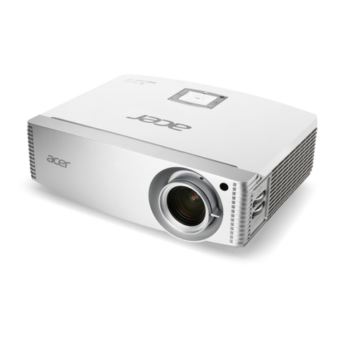
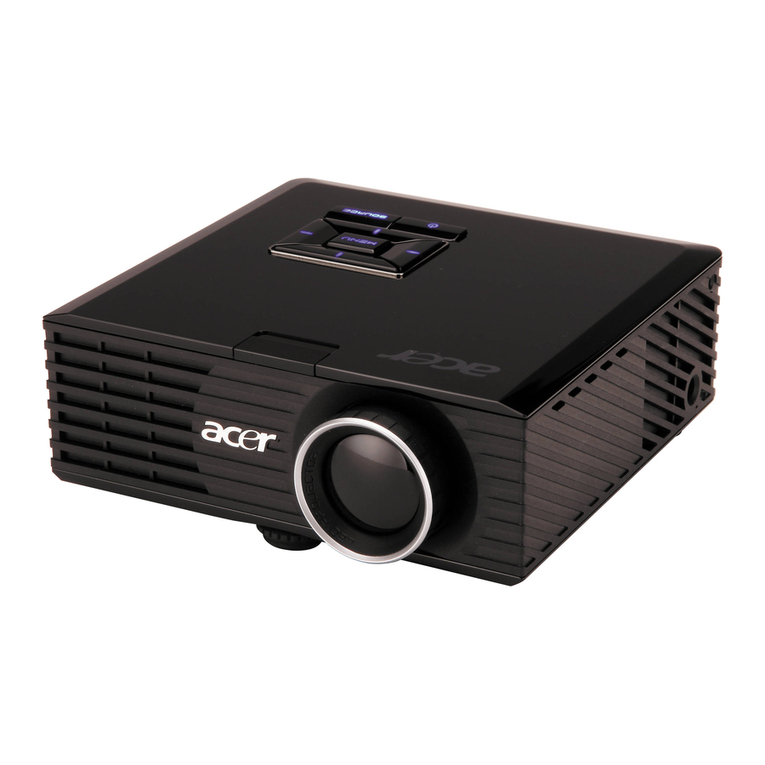
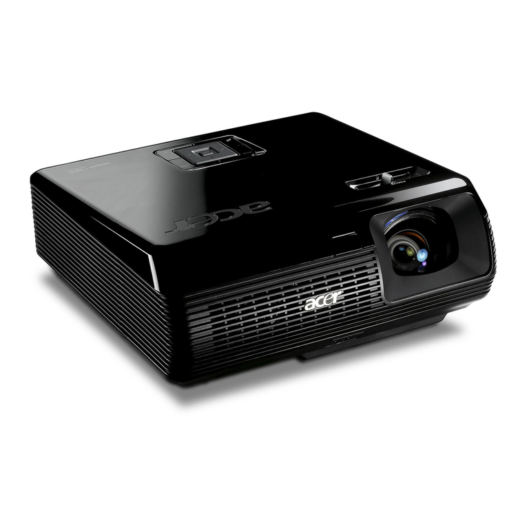
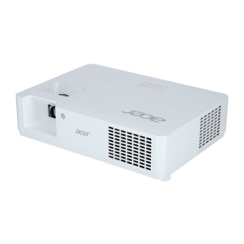
Acer PH530 series User manual

Prepared by SI :
________________________________________
Prepared by TSE :
________________________________________
Checked by :
________________________________________
Approved by :
________________________________________
Model Name : PH530
Date Version Description
2006/08/08 V1.0 Initial Issue
Copyright August, 2006 . All Rights Reserved . P/N#36.86M03G001 .
SERVICE MANUAL

Preface
This manual is applied to PH530 0.62” LVDS DMD 720P Video Projection system.
The manual gives you a brief description of basic technical information to help in service
and maintain the product.
Your customers will appreciate the quick response time when you immediately
identify problems that occur with our products. We expect your customers will appreciate
the service that you offer them.
This manual is for technicians and people who have an electronic background.
Please send the product back to the distributor for repairing and do not attempt to do
anything that is complex or is not mentioned in the troubleshooting.
Notice:
The information found in this manual is subject to change without prior notice. Any
subsequent changes made to the data herein will be incorporated in future edition.
PH530 Service Manual
Copyright August, 2006
All Rights Reserved
Manual Version 1.0
P/N#36.86M03G001
Document#83M-G04-01A
PH530
I
Condential

Table of Contents
Chapter 1 Introduction 1-1
Highlight 1-1
Computer Compatible 1-4
Chapter 2 Disassembly Procedure 2-1
Equipment Needed 2-1
Remove Lamp Module 2-2
Remove Top Cover ,Keypad BD and Rear Cover 2-3
Remove Front Cover,Receiver 2-6
Remove Each Side Cover 2-7
Remove Main Board 2-8
Remove Side Shielding Module 2-9
Remove Fan Module 2-10
Disassemble Lamp Driver Module 2-11
Disassemble LVPS Module 2-12
Disassemble Color Wheel Module 2-13
Remove Engine Module and Fan Module 2-14
Remove Thermal Switch 2-15
Remove Heatsink and 2 Springs 2-16
Disassemble DMD Chip 2-17
Disassemble Focus Ring 2-18
Disassemble Front Light Cut and Right Light Cut 2-19
Remove EMI Shielding Module and Bottom Cover 2-20
Remove Thermal Sensor Board 2-21
Remove Elevator Module 2-22
Remove Lens Support and Interrupter Switch 2-23
Chapter 3 Troubleshooting 3-1
Equipment Needed 3-1
Main procedure 3-1
II
Condential PH530

III
Chapter 4 Function Test and Alignment Procedure 4-1
Test Equipment Needed 4-1
Service Mode 4-1
Test Condition 4-2
Inspection Procedure 4-2
Chapter 5 Firmware Upgrade Procedure 5-1
Equipment Needed 5-1
Firmware Upgrade Mode 5-1
Installation Procedure 5-2
USB Driver Upgrade Procedure 5-4
Firmware Upgrade Procedure 5-6
Chapter 6 EDID Key-in Procedure 6-1
EDID Introduction 6-1
Equipment Needed 6-2
Setup Procedure 6-3
EDID Key-In Procedure 6-4
Appendix Appendix A 7-1
Exploded Overview 7-1
Appendix B 7-28
I.SerialNumberSystemDenition 8-1
II.PCBACodeDenition 8-2
PH530
Condential

1-1 PH530
Condential
Chapter 1
Introduction
1-1 Highlight
No Item Description
1Weight Approx. 6.0 lbs
2Dimension (W x D x H) - 284.1 x 239.0 x 92.2 mm
3Cooling system - Air Tunnel Flow
- Cooling fans with optimized system acoustic noise
level
- Temperature control circuits with adaptive fan rotational
speeds
- High altitude cooling mode
- Maximum touch temperature follow UL60950
4Lamp housing - Lamp Assembly could be changed by customer him
self, but should read the user manual for instruction in
advance.
- Lamp Assembly should be provided by Coretronic and
distributed through authorized agencies
5Tilt angle - 6 degree with elevator mechanism
6 Power supply - Universal AC 100 – 240 V ~ 50-60 Hz with PFC input
- 200W Phoenix(SHP69) Lamp @ normal operation
- Variance FAN speed control (Depends on temperature
variant)
8Power Consumption - Operation: TBD W +/-10% at 110Vac,
Standby < TBD W
9 Input signal spec. - Hsync Frequency 31.5 ~ 100 kHz
- Vsync Frequency 56 ~ 85 Hz
- Video Signal RGB (PC)
- Analog RGB 0.7Vp-p, 75 ohm, Separate TTL H,V Sync
- Analog RGB 1Vp-p, 75 ohm, Sync. On Green signal
- Analog RGB 0.7Vp-p, 75 ohm, Composite TTL Sync.
- Video
- Composite video 1Vp-p,75 ohm
- S-video Luminance 0.714Vp-p, 75 ohm
- Chrominance 0.286Vp-p, 75 ohm
- Component video 1Vp-p, 75 ohm

1-2 PH530
Condential
Item Description
10 Brightness - 700 ANSI Lumens ---typical.
- 590 ANSI Lumens ---engineering minimum.
11 System Controller - TI DDP 3020
12 Video compatibility - Standards :
NTSC - M, 4.43 MHz, 480i
PAL - B, D, G, H, I , M , N, 576i
SECAM - B, D, G, K, K1, L
HDTV - 480i, 480p, 576p, 720p, 1080i
13 Control keypad - 8 Keys
POWER
ReSync
Menu
‘’Up’’/’’Down’’/’’Left’’/’’Right’’ Direction Buttons
Source
14 Keystone correction - +/ - 6 degree
15 Contrast - 2200 : 1 Full On/Full Off ---typical
- 1500 : 1 Full On/Full Off --- engineering minimum
16 Uniformity - 70% Japan standard (Minimum)
- 85% Japan standard (Typical)
17 Projection lens - f = 22.29 mm ~ 26.72 mm, F/2.5 ~ 2.8, 1.2X Manual
Zoom Lens (YM10M)
18 Projection Image Size - Adjustable from 33.55” to 310” -wide (Diagonal for
16:9)
19 LED indicator - Power/Standby : Power ON /Stand-by status indicator
- Lamp : One-minute timer indicator to prevent the hot
re-strike
- Temp : Over-heat & Abnormal indicator
20 Lamp life - 1500 hours min, 50% survival rate (Normal mode)
- 2000 hours min, 50% survival rate (Eco mode)
21 Acoustic noise level 36 dB(A) ( Typical, Under 23±20C; Normal mode )
33 dB(A) (Typical, Under 23±20C; Eco mode )
Noise measurement follows ISO7779, A-weighted sound
pressure level measurement(refer appendix A), 7200
rpm color wheel rotational speed

1-3 PH530
Condential
NO Item Description
22 On-Screen display
Menu
- Multi-language: English, Germany, France, Italian,
Spanish,
Portuguese , Japanese, Chinese-C ,
Chinese-S
User-Friendly design with Icon & Instructions.
Customized OSD UI with start up Screen.
23 Temperature - Operating: 5 -- 35°C
- Storage: -20 -- 60°C
24 Maximum Humidity Operating: 5°C ~ 35°C°, 80%RH (Max.),
Non-condensing
Storage: -20°C ~ 60°C’, 80%RH (Max.),
Non-condensing
25 Altitude - Operating 0 ~ 2,500 ft for 5°C~35°C
2,500 ~ 5,000 ft for 5°C~30°C
5,000 ~ 10,000 ft for 5°C~25°C
- Storage 40,000 ft (Max.)
26 MTBF - Operating more than 12,000 hours (90% Condence
Level)

1-4 PH530
Condential
1-2 Computer Compatible
Compatibility Resolution 85V-Sync (Hz)50
VGA 640 x 480 60
640 x 480 72
640 x 480 75
640 x 480 85
720 x 400 70
720 x 400 85
SVGA 800 x 600 56
800 x 600 60
800 x 600 72
800 x 600 75
800 x 600 85
XGA 1024 x 768 60
1024 x 768 70
1024 x 768 75
1024 x 768 85
SXGA 1152 x 864 70
1152 x 864 75
1152 x 864 85
1280 x 1024 60
1280 x 1024 72
1280 x 1024 75

1-5 PH530
Condential
Compatibility Resolution 85V-Sync (Hz)50
QuadVGA 1280 x 960 60
1280 x 960 75
SXGA+ 1400 x 1050 60
MAC 1152 x 870 75.06
MAC G4 640 x 480 60
i Mac DV 1024 x 768 75

2-1 PH530Condential
2-1 Equipment Needed
Chapter 2
Disassembly Process
Item Photo Item Photo
Screw Bit
(+) :107
Hex Sleeves
5mm
Hex
Sleeves
8mm
Tweezers

2-2 PH530Condential
No Procedure Photo
1Unscrew 2 screws to remove
Lamp Cover.
(as red circle)
2Unscrew 2 screws to
remove Lamp Module.
(as red circle)
2-2 Remove Lamp Module
Lamp
Lamp Cover

2-3 PH530Condential
No Procedure Photo
1(1) Unscrew 3 screws .
(as red circle)
(2) Unplug 1 CNNT.
(as yellow square)
2-3 Remove Top Cover,Keypad BD and Rear Cover

2-4 PH530Condential
No Procedure Photo
2(1) Unscrew 8 screws.
(as red circle)
(2) Unscrew 2 cupreous hex
spacers and 1 iron spacer.
(as blue circle)
(3) Remove iron plate.
(4) Unplug 1 connector.
(as blue square)
(5) Remove Keypad BD.
(as yellow circle)
Top Cover

2-5 PH530Condential
No Procedure Photo
3(1) Unscrew 2 hex screws.
(as green circle)
(2) Remove Rear Cover.

2-6 PH530Condential
No Procedure Photo
1(1) Unplug 1 connector.
(as blue circle)
(2) Remove Front Cover.
(3) Remove Receiver.
Front Cover
2-4 Remove Front Cover,Receiver

2-7 PH530Condential
No Procedure Photo
1(1) Unplug 1 connector.
(as blue circle)
(2) Press 3 tennons on the
left.
(as green ellipse)
(3) Remove left side cover.
(4) Press 3 tennons on the
right.
(as green ellipse)
(5) Remove right side cover.
2-5 Remove Each Side Cover

2-8 PH530Condential
No Procedure Photo
1(1) Unscrew 4 screws.
(as red circle)
(2) Unplug 8 connectors.
(as blue square)
(3) Remove Main BD.
Main BD
2-6 Remove Main Board

2-9 PH530Condential
2-7 Remove Side Shielding Module
No Procedure Photo
1(1) Unscrew 3 screws.
(as red circle)
(2) Press 2 tennons.
(as green ellipse)
(3) Remove Side Shielding
Module.
ENGINE EMI THERMAL PLATE

2-10 PH530Condential
2-8 Remove Fan Module
No Procedure Photo
1(1) Unscrew 2 screws.
(as red circle)
(2) Take off Fan bracket
directly.
(3) Remove Fan.
(as yellow circle)
Fan

2-11 PH530Condential
2-9 Disassemble Lamp Driver Module
No Procedure Photo
1(1) Unscrew 4 screws.
(as red circle)
(2) Unscrew 2 cupreous hex
spacers.
(as blue circle)
(3) Unplug 1 connector.
(as blue square)
(4) Remove Lamp Driver
Module.
Lamp Driver Module
Other manuals for PH530 series
1
Table of contents
Other Acer Projector manuals

Acer
Acer X1110A Series User manual

Acer
Acer P1203PB Series User manual

Acer
Acer XD1270D User manual

Acer
Acer K520 Series User manual

Acer
Acer K650i SERIES User manual

Acer
Acer P5270 - XGA DLP Projector User manual

Acer
Acer H9500BD Series User manual

Acer
Acer X1230PS Series User manual

Acer
Acer D1P1434 Series User manual

Acer
Acer P1165 Series User manual