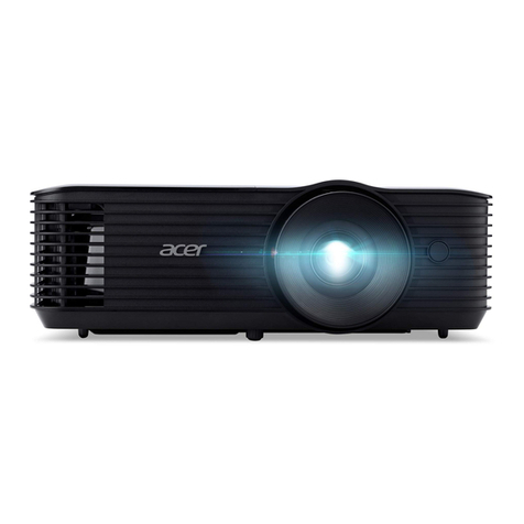
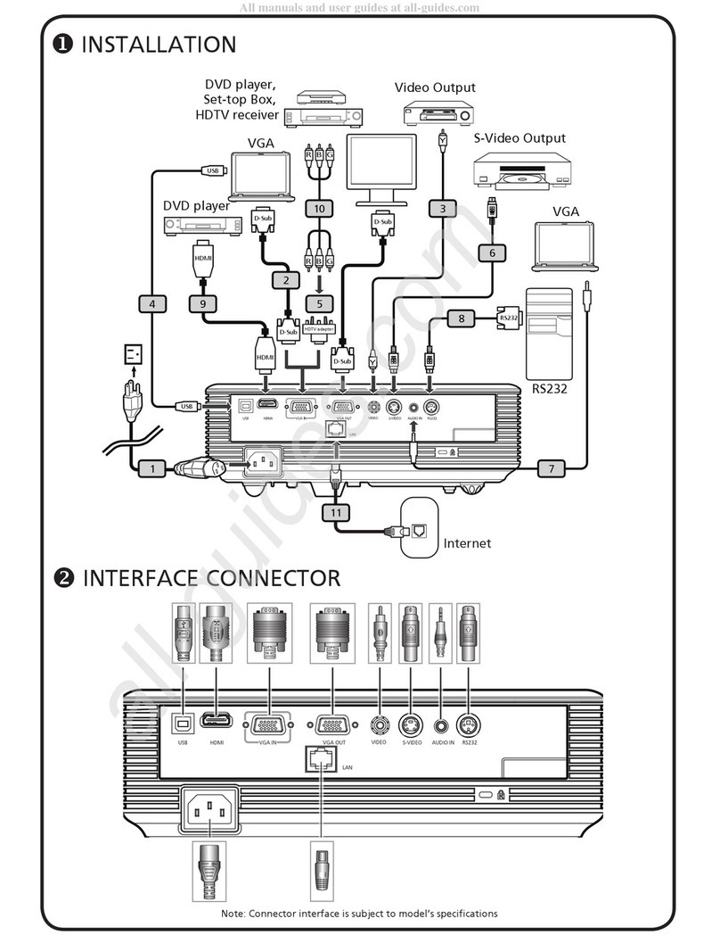
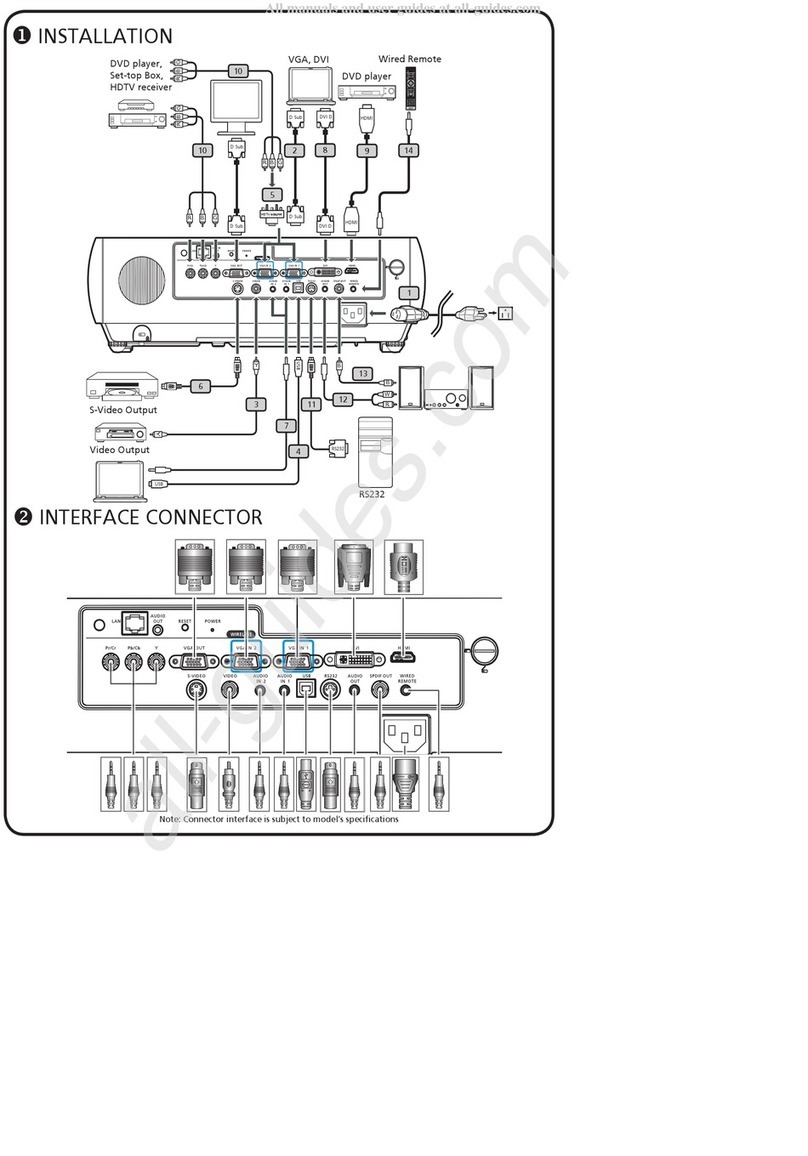
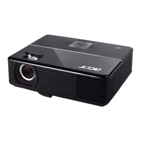
Acer PD721 User manual

Acer PD721
Service Guide
Service CD P/N: N/A
Service guide files and updates are available
on the CSD web; for more information,
please refer to http://csd.acer.com.tw

II
Revision History
Please refer to the table below for the updates made on Acer Altos PD721 service guide.
Date Chapter Updates

III
Copyright
Copyright © 2001 by Acer Incorporated. All rights reserved. No part of this publication may be reproduced,
transmitted, transcribed, stored in a retrieval system, or translated into any language or computer language, i
in any form or by any means, electronic, mechanical, magnetic, optical, chemical, manual or otherwise,
without the prior written permission of Acer Incorporated.
Disclaimer
The information in this guide is subject to change without notice.
Acer Incorporated makes no representations or warranties, either expressed or implied, with respect
to the contents hereof and specifically disclaims any warranties of merchantability or fitness for any
particular purpose. Any Acer Incorporated software described in this manual is sold or licensed "as is".
Should the programs prove defective following their purchase, the buyer (and not Acer Incorporated,
its distributor, or its dealer) assumes the entire cost of all necessary servicing, repair, and any
incidental or consequential damages resulting from any defect in the software.
Acer is a registered trademark of Acer Corporation.
Intel is a registered trademark of Intel Corporation.
Pentium and Pentium II/III are trademarks of Intel Corporation.
Other brand and product names are trademarks and/or registered trademarks of their respective holders.

IV
Conventions
The following conventions are used in this manual
:
Screen messages Denotes actual messages that appear
on screen.
NOTE Gives bits and pieces of additional
information related to the current
topic.
WARNING Alerts you to any damage that might
result from doing or not doing specific
actions.
CAUTION Gives precautionary measures to
avoid possible hardware or software
problems.
IMPORTANT Reminds you to do specific actions
relevant to the accomplishment of
procedures.

V
Preface
Before using this information and the product it supports, please read the following general information.
1. This Service Guide provides you with all technical information relating to the BASIC CONFIGURATION
decided for Acer's "global" product offering. To better fit local market requirements and enhance product
competitiveness, your regional office MAY have decided to extend the functionality of a machine (e.g.
add-on card, modem, or extra memory capability). These LOCALIZED FEATURES will NOT be covered
in this generic service guide. In such cases, please contact your regional offices or the responsible
personnel/channel to provide you with further technical details.
2. Please note WHEN ORDERING FRU PARTS, that you should check the most up-to-date information
available on your regional web or channel. If, for whatever reason, a part number change is made, it will
not be noted in the printed Service Guide. For ACER-AUTHORIZED SERVICE PROVIDERS, your Acer
office may have a DIFFERENT part number code to those given in the FRU list of this printed Service
Guide. You MUST use the list provided by your regional Acer office to order FRU parts for repair and
service of customer machines.

VI

Table of Contents
Chapter 1 System Introduction........................................................................... 1
Technical Specification.................................................................................................1
Product Overview.........................................................................................................3
System BlockDiagram............................................................................................... 6
Chapter 2 Firmware Upgrade..............................................................................10
Setup Procedure..................................................................................................11
Upgrading Procedure............................................................................................11
Chapter 3 MachineDisassemblyandReplacement................................................ 17
Tool Needed.........................................................................................................17
General Information.............................................................................................. 17
Removing Top Cover Module, Keypad Board and Speaker........................................ 18
Removing AV Module and Connector Board............................................................ 20
Removing Lamp Ballast and Power Supply..............................................................21
Removing Lamp Module and Thermal Board............................................................22
Removing Fan Module and Front End Board............................................................23
Removing Formatter Board....................................................................................24
Removing Engine Module......................................................................................25
Chapter 4 Troubleshooting...........................................................................................26
Equipment Needed.............................................................................................. 26
Main Procedure..........................................................................................27
Power Troubleshooting................................................................................28
Performance Troubleshooting.......................................................................29
Function Troubleshooting............................................................................30
Audio Troubleshooting.................................................................................31
Remote Control Troubleshooting..................................................................31
Function Test and Alignment Procedure................................................................32
Equipment Needed....................................................................................32
Test Condition...........................................................................................32
Test Display Modes and Patterns.........................................................................33
Compatible Modes.................................................................................... 33
Function Test Display Pattern.................................................................... 35
Inspection Procedure......................................................................................... 37
i
1Chapter 1
Chapter 1
System Introduction
Technical Specification
metI noitpircseD
yalpsiDPLD
MT
noituloseR ,)867x4201(AGXevitaN desserpmoc)4201x0821(AGXS
ytilibitapmoCretupmoC dna,caMi,hsaotnicaMelppA,selbitapmoCdnaCPMBI )gniziser(AGV,AGVS,AGX,AGXSsdradnatSASEV
ytilibitapmoCoediV ,)N/M/I/H/G/D/B(LAP,)34.4/85.3(MCSTN ,)p084(VTDE,)i0801,p027(VTDH,)L/1K/K/G/D/B(MACES p/i675,)i084(VTDS
oitaRtcepsA elbitapmoC9:61/4:5,evitaN3:4
)lacipyT(oitaRtsartnoC1:0002
sroloCelbayalpsiDsroloCnoilliM7.61
)lacipyT(ssenthgirBsnemuLISNA003,2
sneLnoitcejorP mm5.43~8.82=f,96.2~44.2/F sucoFlaunaMdnamooZlaunaM21.1:1
)lanogaiD(eziSneercSnoitcejorP)m52.6("642~)m85.0("32
ecnatsiDnoitcejorP)m01('8.23~)m41.1('47.3
etaRnacSlatnoziroHzHk001~51
etaRnacShserfeRlacitreVzH021~34
epyTpmaL pmaLPHUelbaecalpeRresUW052
efiLpmaLsruoH000,2
noitcerroCenotsyeKseergeD61-/+
thgieW)gk3(sbl6.6
noisnemiD )"3.3x"9.8x"9.01(mm58x522x772
lortnoCesuoMetomeR retnioPresaL&noitcnuFesuoMhtiwlortnoCetomeR
ylppuSrewoP ylppusrewopgnihctiws-otuaV042-001tupnICA
noitpmusnoCrewoPsttaW023
erutarepmeTnoitarepO5
o
53~C
o
14/C
o
59~F
o
F
)lacipyT(leveLesioNnoitarepOlamroNniBd23
ytimrofinU%09

Chapter 1 2
metI noitpircseD
srotcennoCO/I
tupnIretupmoC )troptupniVTDH/tnenopmoC/AGV(buS-DniP-51BDH1- rotcennoCIVD1- )IVDrof1,BUS-Dnip-51rof1(kcaJiniMoiduA2-
tupnIVA rotcennoCtupnIoediV-SrofNIDiniM1- rotcennoCtupnIoediVetisopmoCrofkcaJACR1- oediVetisopmoC/oediV-SrofkcaJiniMoiduA1-
tuptuO hguorhTpooLrotinoMrofniP-51BUS-DiniM1- hguorhtpoolrotinomrofkcaJiniMoiduA1- troPesuoMetomeR1-
seirosseccAdradnatS
droCrewoPCA )M8.1(elbaClangiSAGVniP-51 elbaCoediVVTDH/etisopmoCACR elbaClangiSoediV-S
resaldnanoitcnufesuomhtiwlortnoCetomeRsseleriW retniop
etomerrof2XseorettaBe[uTAA )MOR-DC(ediugs'resuegaugnal-itlum dractratskciuqegaugnal-itlum pacsnel gabgniyrractfos ACR/kcajelbacoiduA )tropmoC/BSUtroppus(lortnocetomerrofelbacY

3Chapter 1
Product Overview
Main Unit
metI noitpircseD
1lortnoClenaP
2hctiwSrewoProtcennoCrewoP
3stroPnoitcennoC
4gniRsucoF
5sneLmooZ
6gniRmooZ
7rekaepS
8revieceRlortnoCetomeR
9nottuBrotavelE
01tooFrotavelE

Chapter 1 4
Panel Control
metI noitpircseD
1DELgninraWpmaL
2DELgninraWerutarepmeT
3emuloV
4etuM
5)ffO/nO(uneM
6syeKtceleSlanoitceriDruoF
7retnE
8mooZ
9cnys-eR
01ecruoS
11ybdnatS/rewoP

5Chapter 1
Connection Ports
metI noitpircseD
1rotcennoCtupnI232SR
2oediVroftupnIoiduA
3rotcennoCtupnIoediVetisopmoC
4rotcennoCtupnIoediV-S
5IVDroftupnIoiduA
6rotcennoCtupnIIVD
7retupmoCroftupnIoiduA
8 rotcennoCoediVtnenopmoC/VTDH/langiSgolanACP
9rotcennoCtuptuOoiduA
01rotcennoChguorht-pooLrotinoM
11rotcennoCtupnIesuoMetomeR
21hctiwSrewoP
31rotcennoCrewoP

Chapter 1 6
System Block Diagram
D-Sub
Output
S-Video
Video
Audio
DVI
D-Sub
Mouse
RS232
Input
Speaker
Front-End
Board
Inter Lock
Switch
LVPS
Module
IR Receiver
Fan
Thermal
Board
Thermal
Sensor
Formatter
Board
Module
Lamp
Ballast
Module
Keypad
Photo
Sensor
LAMP
Module
Color Wheel
Thermal
Switch

7Chapter 1
Main Board Block Diagram
D-Sub output
Analog Input
Digital Input
VideoDecoder
Memory
Image Process
MIS
Thermal Board
LVPS Module
DMD Module
R.G.B.H.Vsync
Digital R.G.B data
H.Vsync
SDA
SCL
GCLK
y (0-7)
UV (0-7)
GM-VHS
GM-VVS
GM-VPEN
GM-VCLK
Standby out
7 Sec
RESET
MCLK
DCLK
KDS (0-3)
KDR (0-2)
ERR
Standby-1
ECOMODE
LAMP Lit
Digital R.G.B Data
DCLK0
DENR
DVS
DHS
LAMP ON/ Lamp Lit
RESET# / Lamp Lit
RESET0 / Lamp Lit
LAMP-IN
LAMP-OUT

Chapter 1 8
Thermal Board Block Diagram
THERMAL BOARD Interface
FAN 1-4
THERMAL
SWITCH
THERMAL
SENSOR
LM75
MAIN
BOARD
KEY PAD
20P Connector to
Formatter Board
16P Connector
3P Connector *4
2P Connector
4P Connector *2
STB
ECON
KEY 7PIN
ERR_OUT
LAMPMISS
POWER 15V, 5VA
STANDBY
ERR_OUT
IR_ON

9Chapter 1
Formatter Block Diagram
VCC2,VOFFSET,VBIAS
VERSETGENERATION
RESETASIC
DMD
0.7” XGA
DATAPATH
FORMATTER
DPF2A
SDRAM B
SDRAMA
ALLEGRO
MOTOR
CONTROL
MICRO
CONTROLLER
CONTROL
FPGA
CONFIG/
SEQUENCE
PROM
CUSTOMER INTERFACE CONNECTOR
VCC2 (DMD)
VCC2 (ASIC)
VOFFSET
VBIAS
VRESET
+5V +12V
CLOCK
OSC
DPF2A CONTROL
VSYNCZ
HSYNCZ
ACTDATA
TFIELD
OLACT
SYNCVAL
LAMP CONTROL&STATUS
COLOR WHEEL INDEX
FPGA CLK
FLASH
PROGRAMMING
HEADER
IIC BUS
HITACHI
DOWNLOAD
HEADER
CLKIN
COLOR
WHEEL
CONTROL
COLOR WHEEL STATUS
CWRSTZ
VOLTAGE ENABLES
BIAS BIN
BIAS/RESET CONTROL
DMD CONTROL
PBUS2
MENORY CONTROL A
MENORY ADDRESS A(12)
MENORY CONTROL B
DMD CONTROL
COLOR
WHEEL
DRIVE
DATA (8)
VSYNCZ, RESETZ
ADDRESS (19)
MBIASRST (16)
INPUTCLK
FPGA CLK
DMD CLK
SDRAM CLK
DATA(0..63)
DMDDATA(0..63)
MENORY ADDRESS A(12)
MENORY ADDRESS B(12)

Chapter 2 10
Firmware Upgrade
Chapter 2
This chapter provides the equipment needed, setup and upgrading procedure for Firmware
upgrade.
Equipment Needed
metI noitpircseD
erawtfoS
exa.edoctooB
xeh.edoctooB
xeh.atadgifnoC
xeh.iuG
exa.edoCmoR
xeh.rehsalF
fni.KDSwp
txt.muSkhC
xeh.rehsalF
exe.MUSPSID
noitacilppACFMredargpUhsalF
erawdraH
:erutxiF )mm0081NIP3niDiniMoTeulB(232-SRelbaC- )A.veR,100.10368.24:N/P(
CP
rotcejorP127DP

11 Chapter 2
Setup Procedure
1. Connect RS232 to mini din 3P Cable to COM1 of PC and PD721.
DFP Port
COM1
Upgrading Procedure
1. Execute “FlashUpgrader MFCApplication”.

Chapter 2 12
2. Click “Choose” button.
1
2
3. Search <pwSDK.inf> file from PD721 F/W folder, then click “Open” button.
PD721-V05-2002.08.13\
PD721-V05-2002.08.13

13 Chapter 2
4. Select “Serial” Port.
5. Select “COM1” port.
PD721-V05-2002.08.13
Other manuals for PD721
1
Table of contents
Other Acer Projector manuals

Acer
Acer P3250 Refresh User manual

Acer
Acer S1213Hne Series User manual

Acer
Acer PD-113P User manual

Acer
Acer B123D Series User manual

Acer
Acer D655F User manual

Acer
Acer PD110 User manual

Acer
Acer H7532BD User manual

Acer
Acer K520 Series User manual

Acer
Acer H6805BDa User manual

Acer
Acer H7531D Series User manual