aci SUN SHIELD HUMIDITY Series Installation instructions

Automation Components, Inc.
2305 Pleasant View Road | Middleton, WI 53562
Phone: 1-888-967-5224 | Website: workaci.com
Page 1
Version: 6.0
I0000647
SUN SHIELD HUMIDITY
SERIES
Installation & Operation Instructions
GENERAL INFORMATION
The Solar Radiation Shield is a solution for
protecting temperature and relative humidity
sensors from error-producing solar radiation and
precipitation. The highly reective white wedge-
shaped plates provide maximum airow around
the sensors while at the same time minimizing
direct exposure to sunlight. The passive shield is
shaped to allow natural air convection around the
sensors so that the air temperature and relative
humidity inside the shield is a good representation
of the outside air. The RH Sun Shield transmitter
is eld selectable with a 4-20 mA, 0-5 VDC, or
0-10 VDC output signal that is equivalent to 0
to 100% RH. This sensor is designed for use with
electronic controllers in commercial heating and
cooling building management systems. All units
are shipped from the factory set up for a 4-20
mA output. The transmitter can also include an
optional temperature sensor for monitoring the
space temperature.
For optimal readings, follow these tips:
• Place the shield in an open area to insure
unrestricted air ow or wind
• Keep away from large radiant heat sources, such
as sun exposed buildings and solar panels.
• Avoid building exhaust vents, electrical
machinery, and motors.
• Do not install over or near sprinklers. Continuous
moisture may damage the sensors.
Phone: 1-888-967-5224
Website: workaci.com
MOUNTING INSTRUCTIONS
The Solar Radiation Shield is designed for two
dierent mounting congurations such as a metal
pipe with outside diameter between 1" and 1.5"
(U-Bolts included) or on the side of a building or
wooden post (Hardware Not included).
Pole Mounting
• Locate the four U-Bolt mounting holes on the
back panel of the mounting bracket. Attach the
U-Bolts, U-Bolt Washers and 5/16" Hex Nuts as
shown in Figure 2.
FIGURE 2: MOUNT BRACKET
FIGURE 1: ENCLOSURE DIMENSIONS
[94.0mm]
3.70in
[56.7mm]
2.23in
[379.7mm]
14.95in
[64.8mm]
2.55in

Automation Components, Inc.
2305 Pleasant View Road | Middleton, WI 53562
Phone: 1-888-967-5224 | Website: workaci.com
Page 2
Version: 6.0
I0000647
FIGURE 3: SENSOR PROBE/
ENCLOSURE REMOVAL
Note: The mounting bracket can be removed from
the shield if needed for easier access. Loosen the
two Phillip screws holding the probe retaining clip
until the sensor probe/enclosure is loose enough
to remove as shown in Figure 3.
• Finger tighten the assembly around the
mounting pole. With a level, make sure the solar
radiation shield is level, and tighten the hex nuts
with a wrench.
Surface Mounting
• Loosen the two Phillip screws holding the probe
retaining clip until the sensor probe/enclosure is
loose enough to remove as shown in Figure 3.
• Attach the mounting bracket directly to the wall
or post(Hardware not included).
• Slide the sensor probe/enclosure back into the
shield. Tighten the two Phillip screws holding
the probe retaining clip until the sensor probe/
enclosure is tight.
Install the PG11 watertight tting supplied
with the sensor if not using conduit. The outer
knockout ring (PG 11/16) on housing should not
be removed when using a ½" NPT conduit tting.
The 4X enclosure has (4) screws. Conrm gasketed
cover is fastened securely in order to prevent any
moisture being introduced into housing.
Refer to Wiring Instructions) to make necessary
connections.
WIRING INSTRUCTIONS
PRECAUTIONS
• Remove power before wiring. Never connect
or disconnect wiring with power applied.
• When using a shielded cable, ground the
shield only at the controller end. Grounding
both ends can cause a ground loop.
• Do not run the temperature sensor wiring in
any conduit with line voltage (24/120/230
VAC) if utilizing resistance temperature signal.
• It is recommended you use an isolated UL-
listed class 2 transformer when powering the
unit with 24 VAC. Failure to wire the devices
with the correct polarity when sharing
transformers may result in damage to any
device powered by the shared transformer.
• If the 24 VDC or 24VAC power is shared
with devices that have coils such as relays,
solenoids, or other inductors, each coil must
have an MOV, DC/AC Transorb, Transient
Voltage Suppressor (ACI Part: 142583), or
diode placed across the coil or inductor. The
cathode, or banded side of the DC Transorb
or diode, connects to the positive side of the
power supply. Without these snubbers, coils
produce very large voltage spikes when de-
energizing that can cause malfunction or
destruction of electronic circuits.
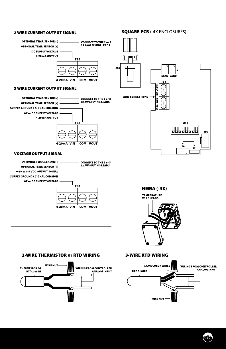
RELATIVE HUMIDITY WIRING
INSTRUCTIONS
Open the cover of the enclosure. ACI recommends
16 to 26 AWG twisted pair wires or shielded cable
for all transmitters. Twisted pair may be used for
2-wire current output transmitters or 3-wire for
voltage output. Refer to FIGURE 4 (p. 3) or wiring
diagrams.
TEMPERATURE WIRING INSTRUCTIONS
ACI recommends 16 to 26 AWG twisted pair wires
or shielded cable for all temperature sensors.
ACI recommends a separate cable be pulled for
Temperature signal only. Temperature Signal
wiring must be run separate from low and high
voltage wires (24/120/230VAC). All ACI thermistors
and RTD temperature sensors are both non-
polarity and non-position sensitive.
All thermistor type units are supplied with (2)
ying lead wires, and all RTD’s are supplied with
(2) or (3) ying lead wires – see FIGURE 6 (p. 3).

Automation Components, Inc.
2305 Pleasant View Road | Middleton, WI 53562
Phone: 1-888-967-5224 | Website: workaci.com
Page 3
Version: 6.0
I0000647
FIGURE 4: OUTPUT SIGNALS FIGURE 5: PRINTED CIRCUIT BOARD
FIGURE 6: TEMPERATURE WIRING
ON
4
236
PUSH TAB IN AND PULL UP ON THE SENSOR
CABLE TO REMOVE FROM J13 CONNECTOR
FACTORY USE ONLY
1 5 7 8

Automation Components, Inc.
2305 Pleasant View Road | Middleton, WI 53562
Phone: 1-888-967-5224 | Website: workaci.com
Page 4
Version: 6.0
I0000647
The number of wires needed depends on the
application. Connect thermistor/RTD wire leads
to controller analog input wires using wire nuts,
terminal blocks, or crimp style connectors. All
wiring must comply with local and National
Electric Codes. After wiring, attach the cover to the
enclosure.
Note: When using a shielded cable, be sure to
connect only (1) end of the shield to ground at the
controller. Connecting both ends of the shield to
ground may cause a ground loop. When removing
the shield from the sensor end, make sure to
properly trim the shield to prevent any chance of
shorting.
Note: If the controller requires a (2) wire input for
a RTD, connect the (2) common wires (same color)
together. If the controller requires (3) wires, use (3)
individual wires - see FIGURE 6 (p. 3).
OUTPUT SIGNALS
Switches 6, 7, and 8 are used to set the RH output
signal. Refer to FIGURE 7 for switch settings.
WIRING INSTRUCTIONS (Continued)
FIGURE 7: OUTPUT SELECTION
SWICHES
ON
268
1
OFF
0-10 VDC Output
0-5 VDC Output
4
3
OFF
5
ON
7
ON
23 78
ON
14 56
OFF
ON
48
4-20 mA Output
1
ON
23 56 7
HUMIDITY REVERSE ACTING OUTPUT
The output is direct acting and can be changed to
reverse acting mode. The output range stays the
same but the corresponding RH value is opposite.
Example:
Direct Acting (DA)
0-10 V output mode,
0 V = 0% RH and 10 V = 100% RH
Reverse Acting (RA)
0-10 V output mode,
0 V = 100% and 10 V = 0%
To change the transmitter to reverse acting or
back to direct acting, set switch 4 to ON to put the
unit in setup mode. After switch 4 is on, turning
switch 2 to ON will put the unit in direct/reverse
acting mode. When switch 2 is set to ON, the out-
put can be used to show if the unit is in direct or
reverse acting mode. For direct acting, the output
will be 1 V for 0-5 V, 2 V for 0-10 V, and 7.2 mA for
4-20 mA. For reverse acting the output will be 4 V
for 0-5 V, 8 V for 0-10 V, and 16.8 mA for 4-20 mA.
With switches 2 and 4 ON, each time switch 5 is set
to ON the output will change to reverse acting or
direct acting.
To reset the unit to the default setting, toggle both
switches 5 and 6 ON then OFF while both switches
2 and 4 are ON.
When all calibration is completed, remember to
place the switches back into the positions that
correspond to the output needed as shown in
FIGURE 7.
RH CALIBRATION INSTRUCTIONS
Note: This is only a single point calibration. All
transmitters are factory calibrated to meet/exceed
published specications. Field adjustment should
not be necessary.
The dipswitch allows the user to calibrate the sen-
sor through the software. Setting switch 4 ON will
put the transmitter into setup mode allowing the
increment and decrement to work.
Once in setup mode, the output will change to
50% (2.5 V for 0-5 V, 5 V for 0-10 V, 12 mA for 4-20
mA). Each increment or decrement step will cause
the output to change by 0.1 V for 0-5 V, 0.2 V for
0-10 V, and 0.32 mA for 4-20 mA in setup mode.

Automation Components, Inc.
2305 Pleasant View Road | Middleton, WI 53562
Phone: 1-888-967-5224 | Website: workaci.com
Page 5
Version: 6.0
I0000647
This can be used to show the user how far oset the transmitter is. To see the starting point again set
switch 1 ON. This will show the 50% output again. When the unit is out of setup mode the output will go
back to RH output. The maximum oset is 10%. There can be a total of 20 increments.
Increment RH Output
This will shift the RH output linearly up in 0.5% steps. Switch 4 must be set to ON rst. After switch 4 is on,
each time switch 5 is set ON the RH output will increase by 0.5%. The increase goes into eect each time
switch 5 is set to ON.
Decrement RH Output
This will shift the RH output linearly down in 0.5% steps. Switch 4 must be set to ON rst. After switch 4 is
on, each time switch 6 is set ON the RH output will decrease by 0.5%. The decrease goes into eect each
time switch 6 is set to ON.
Reset RH Output
This will reset the RH output back to the original calibration. Switch 4 must be set to ON rst. After switch
4 is on, toggle switches 5 and 6 ON then OFF. After 5 and 6 are OFF slide switch 4 OFF.
When all calibration is completed, remember to place the switches back into the positions that corre-
spond to the output needed as shown in FIGURE 8.
RH CALIBRATION (Continued)
TEST INSTRUCTIONS
Test mode will make the transmitter output a xed
0%, 50%, or 100% value. The sensor will not aect
the transmitter output. This is used for trouble-
shooting or testing only.
Switches 1, 2, and 3 are used for test mode. The
output will be a xed 0%, 50%, or 100% signal that
corresponds to the output selected with switches
6, 7, and 8. Refer to FIGURE 8 for switch settings.
FIGURE 8: TEST SELECTION SWITCHES
ON
268
1
OFF
50% RH Output
100% RH Output
4
3
OFF
5
ON
7
ON
23 78
ON
14 56
OFF
ON
48
0% RH Output
1
ON
23 56 7
RH CONVERSION FORMULAS
Formula:
Example:
4 -20 mA
([mA signal] -4) / 0.16 = percent RH
12 mA output signal
(12 - 4) / 0.16 = 50% RH
0-5 VDC
[VDC signal] / 0.05 = percent RH
1.25 vdc output signal
1.25 / 0.05 = 25% RH
0-10 VDC
[VDC signal] / 0.10 = percent RH
7.50 vdc output signal
7.50 / 0.10 = 75% RH

Automation Components, Inc.
2305 Pleasant View Road | Middleton, WI 53562
Phone: 1-888-967-5224 | Website: workaci.com
Page 6
Version: 6.0
I0000647
PRODUCT SPECIFICATIONS

Automation Components, Inc.
2305 Pleasant View Road | Middleton, WI 53562
Phone: 1-888-967-5224 | Website: workaci.com
Page 7
Version: 6.0
I0000647
TROUBLESHOOTING
WARRANTY
The ACI Outside Series RH sensors are covered by ACI’s Five (5) Year Limited Warranty, which is
located in the front of ACI’S SENSORS & TRANSMITTERS CATALOG or can be found on ACI’s website:
www.workaci.com.
W.E.E.E. DIRECTIVE
At the end of their useful life the packaging and product should be disposed of via a suitable recycling
centre. Do not dispose of with household waste. Do not burn.

Automation Components, Inc.
2305 Pleasant View Road | Middleton, WI 53562
Phone: 1-888-967-5224 | Website: workaci.com
Page 8
Version: 6.0
I0000647
Automation Components, Inc.
2305 Pleasant View Road
Middleton, WI 53562
Phone: 1-888-967-5224
Website: workaci.com
Table of contents
Popular Inverter manuals by other brands

Generac Power Systems
Generac Power Systems Guardian 5410 Repair manual

Sherman hobby
Sherman hobby MMA 200 SPeeDY user manual

Proecotec
Proecotec ENERGY ONE Series instruction manual

Voltronic Power
Voltronic Power AXPERT MAX II 8KW Service manual

Kaisai
Kaisai KOB30U-18HFN32 Service manual

SunSynk
SunSynk SUNSYNK MAX user manual