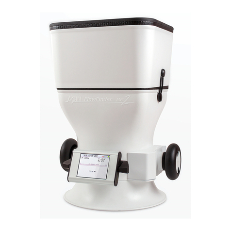
ACIN Betz 2500/250 User manual

Betz micromanometer
HANDLEIDING
MANUAL
MODEL 2500/250
MODEL 5000/500
instrumenten bv


3
HANDLEIDING BETZ MICROMANOMETER.................... 2
1. BESCHRIJVING ...................................................................................2
2. LEVERINGSOMVANG ...........................................................................2
3. TEKENING ...........................................................................................3
4. SPECIFICATIES ...................................................................................3
5. INSTALLATIE .......................................................................................4
6. GEBRUIK INSTRUMENT.......................................................................5
7. ONDERHOUD.......................................................................................6
8. KALIBRATIE.........................................................................................6
9. TRANSPORT........................................................................................6
MANUAL BETZ MICROMANOMETER ........................... 7
1. DESCRIPTION .....................................................................................7
2. SCOPE OF DELIVERY ..........................................................................7
3. DRAWING ............................................................................................8
4. SPECIFICATIONS ................................................................................8
5. INSTALLATION ....................................................................................9
6. OPERATION.......................................................................................10
7. MAINTENANCE..................................................................................11
8. RECALIBRATION ...............................................................................11
9. TRANSPORT......................................................................................11
DATA BETZ............................................................................................12
EN
NL
betz micromanometer

4
De Betz micromanometer is een instrument voor het meten van lage lucht-, gas- of verschildruk met
hoge nauwkeurigheid en uitstekende lange termijnstabiliteit. De Betz micromanometer is een J-buis
manometer waarin het vloeistofniveau wordt gemeten met behulp van een drijvende liniaal. Drukverandering
zal resulteren in een verandering van het vloeistofniveau. Een weergave van de liniaal 25x vergroot wordt
geprojecteerd op het projectiescherm.
Toepassingen
• als fabrieksstandaard voor de kalibratie van drukmeetinstrumenten
• voor precieze en betrouwbare metingen van extreem kleine drukverschillen
• voor continue weergave van (extreem kleine) drukverschillen
Standaardkalibratie en schaaleenheid is Pascal (Pa). De Betz micromanometer is verkrijgbaar in twee be-
reiken: 2500 en 5000 Pa. Kalibratie in mmH2O of kgf/m2is mogelijk.
Een nieuwe Betz micromanometer wordt gekalibreerd door een ISO/IEC 17025 geaccrediteerde kalibra-
tielaboratorium. De kalibratie wordt uitgevoerd met inachtneming van de aantrekkingskracht van de aarde
(g-waarde) op de locatie waar het instrument gebruikt gaat worden.
1. beschrijving
Leveringsomvang
• 1 micromanometer
• 1 liniaal in liniaaldoos (bewaren voor toekomstig transport)
• 1 koudlichtbron met lichtgeleider
• 1 fles meetvloeistof
• 1 kalibratiecertificaat
• 1 handleiding
2. leveringsomvang
handleiding betz micromanometer
nederlands

5
nederlands
3. tekening
1. nulstelschroef
2. kalibratiepen
3. waterpas
4. drukaansluitingen
5. glazen drijver
6. glazen liniaal
7. liniaalopvang
8. liniaalgeleider
9. stijgbuis
10. vastzetschroef
11. lichtgeleider
12. vloeistofniveauregelaar
13. stelpootjes
14. aftapplug
15. objectief
16. projectiescherm met
schaalverdeling
4. specificaties
SPECIFICATIES Betz type 2500 Betz type 5000
meetbereik (in Pascal) -50 tot 2500 Pa -100 tot 5000 Pa
nauwkeurigheid meetwaarde 0,04% FS 0,04% FS
resolutie 0,1 Pa 0,2 Pa
maximum statische druk 100 kPa 100 kPa
hoogte referentieniveau boven tafelblad 335 mm ± 10 mm 335 mm ± 10 mm
kalibratietemperatuur 20 ºC 20 ºC
afmetingen (l x b x h) 390 x 204 x 650 mm 390 x 204 x 675 mm
gewicht ±13 kg ± 16 kg
meetvloeistof gedemineraliseerd water met ontspanningsmiddel
netspanning en -frequentie (standaard) 220/240 VAC, 50/60 Hz
materiaal
kritische meetonderdelen RVS en glas
andere interne onderdelen RVS en vernikkeld messing
behuizing aluminium plaat, grijs gelakt
aansluiting verschildrukmeting slangpilaar, messing vernikkeld
geschikt voor slangen met inwendige diameter ø4 .. ø8 mm

6
5.1 installatie van de micromanometer
• De micromanometer moet worden opgesteld op een stabiel en robuust (tafel)oppervlak.
Het is absoluut noodzakelijk om het instrument waterpas te plaatsen. Dit wordt gedaan door middel van
de 3 stelpootjes (13), gebruikmakend van de waterpas (3) bovenop
5.2 installatie van de koudlichtbron
• Zorg ervoor dat de netspanning voor de koudlichtbron correct is (zie 4. specificaties).
• Plaats het dunne eind van de lichtgeleider (11) in de achterkant van de micromanometer en fixeer dit
met met behulp van de vastzetschroef (10).
• Sluit het andere einde aan op de koudlichtbron. Schakel de koudlichtbron naar stand “1”.
5.3 vullen met meetvloeistof en installatie van de liniaal
• De meetvloeistof wordt geleverd in 1 fles van 1000 ml (model 250/2500) of twee flessen van 1000 ml
(model 500/5000).
• De glazen liniaal (6) met de glazen drijver (5) is verpakt in een liniaaldoos om breken tijdens het trans-
port te voorkomen. Wij raden u aan deze doos te bewaren voor toekomstig transport van het instrument.
• Verwijder de schroefring met (-) drukaansluiting van de stijgbuis (9).
• Draai de 4 schroeven van de drukring rondom de stijgbuis (9) los.
• Trek voorzichtig de stijgbuis met drukring omhoog en verwijder deze van het instrument.
• Vul de micromanometer mt de bijgeleverde meetvloeistof. Doe dit langzaam en voorzichtig, de vloeistof
heeft neiging tot schuimen.
• Inhoud vloeistofreservoir: ± 400 ml (model 250/2500), ± 1300 ml (model 500/5000)
• Neem de glazen liniaal (6) met drijver (5) uit de liniaaldoos door deze vast te houden aan de punt bo-
venop de glazen bol. Raak drijver en liniaal zelf niet aan, deze moeten schoon blijven.
• Houd de liniaal in vertikale positie vast bij de punt van de drijver, met de schaalverdeling op de liniaal
aan dezelfde kant als het projectiescherm (16), plaats de onderzijde van de liniaal in de liniaalgeleider
(8) en laat deze voorzichtig hierin zakken totdat de drijver rust op de liniaalopvang (7).
• Plaats de stijgbuis voorzichtig terug op de micromanometer en monteer de drukring weer met behulp
van de 4 schroeven. Gebruik geen vet, de O-ring onder de drukring moet schoon blijven.
• Draai de 4 schroeven kruislings beetje bij beetje aan totdat de stijgbuis weer stevig vastzit.
• Controleer het beeld van de liniaal dat nu op het scherm wordt geprojecteerd. Beeldscherpte en helder-
heid kunnen worden beïnvloed door verstellen van de lichtgeleider, na iets losdraaien van de vastzet-
schroef (10).
• Nu kan de nulstelling worden gecontroleerd. Het vloeistofniveau moet zodanig zijn dat de geprojec-
teerde nulstreep van de liniaal samenvalt met de nulstreep op het verstelbare projectiescherm (16), als
dit in de middenstand is gezet door middel van de nulstelschroef (1).
• Als er een negatieve aflezing is, is het vloeistofniveau te laag. Voeg wat vloeistof toe via de stijgbuis tot-
dat het instrument nul aanwijst. Laat de vloeistof langzaam en voorzichtig langs de binnenwand van de
stijgbuis lopen, om schuimvorming te voorkomen.
• Als er een positieve aflezing is, is het vloeistofniveau te hoog. Tap wat vloeistof af met behulp van de
vloeistofniveauregelaar (12) aan de achterzijde, totdat het instrument nul aanwijst.
• Fijninstelling kan worden gedaan met de nulstelschroef (1).
• Wacht minimaal 8 uur totdat het schuim in de vloeistof is verdwenen.
NB.
De nummers (..) refereren aan de tekening op pagina 3.
5. installatie
nederlands

7
6.1 vóór gebruik
aflezing
• Pas de positie van het einde van de lichtgeleider (11) aan om een optimale kwaliteit en lichtintensiteit
van het geprojecteerde beeld te verkrijgen.
correct vloeistofniveau
• Stel in een drukloze situatie het projectiescherm (16) in de middenstand met de nulstelschroef (1).
• Het vloeistofniveau is correct als de geprojecteerde nulstreep van de liniaal samenvalt met de nulstreep
van het verstelbare projectiescherm.
• Als er een substantiële afwijking van de nulstand is die niet met behulp van (1) kan worden gecorri-
geerd, zie 5.3 om het vloeistofniveau aan te passen.
lekkage
• Controleer of de conussen van beide slangaansluitingen (4) schoon en olievrij zijn en druk ze stevig in
hun aansluiting.
• Sluit de (+) en (-) drukaansluitingen (4) aan op een drukverschilbron door middel van twee flexibele
slangen met een inwendige diameter van ø4 .. ø8 mm.
• Verhoog geleidelijk de druk tot de maximale waarde. Sluit de toevoerslang (+) en controleer of de mi-
cromanometer de aflezing een tijdje vasthoudt. Zo niet, controleer alle aansluitingen en slangen.
• Laat de druk nu weer langzaam naar nul dalen. Als de aanwijzing goed terugkomt op nul is het instru-
ment klaar voor gebruik.
• Deze procedure zorgt ook voor de noodzakelijke bevochtiging van het inwendige van de stijgbuis.
6.2 tijdens gebruik
Let erop dat tijdens het meten de aangeboden druk de maximale meetcapaciteit niet overschrijdt. Als dit
toch gebeurt, moet het vloeistofniveau opnieuw gecontroleerd worden. Controleer daarnaast of er geen
meetvloeistof de (min)-drukaansluiting bereikt heeft. Schroef de topring van de stijgbuis los en let erop dat er
geen druppels vloeistof aanwezig zijn. Wanneer snelle drukvariaties mogelijk zijn, is het verstandig om dem-
ping toe te passen in de toevoerslang, bijvoorbeeld door middel van een restrictie of een verstelbare clip.
Omdat het licht dat het instrument via de lichtgeleider bereikt het instrument niet opwarmt, is het mogelijk
om de koudlichtbron voor langere tijd aan te laten staan. Echter, plaats de koudlichtbron niet te dicht bij het
instrument, om opwarming door straling te voorkomen. Onder normale omstandigheden kiest u voor stand
1 voor de maximale levensduur van de lamp (± 10 000 uur).
6.3 temperatuurcorrectie
De micromanometer is gekalibreerd bij 20°C. Als de micromanometer wordt gebruikt buiten een gecon-
ditioneerde ruimte, zorg er dan voor dat de omgevingstemperatuur constant blijft tijdens de metingen en
gebruik een correctiefactor:
6. gebruik instrument
temperatuur (°C) correctiefactor
15 1.00090
16 1.00075
17 1.00050
18 1.00035
temperatuur (°C) correctiefactor
19 1.00015
20 1.00000
21 0.99975
22 0.99950
6.4 voorbeelden van aflezing
Betz type 2500
De glazen liniaal is onderverdeeld in 10
Pa, de schaalverdeling van het projec-
tiescherm in 1 Pa. Voorbeeld geeft de
waarde van 1579.3 Pa
Betz type 5000
De glazen liniaal is onderverdeeld in 10
Pa, met waarden per 20 Pa. De schaal-
verdeling is onderverdeeld in 2 Pa. Voor-
beeld geeft de waarde van 3514.8 Pa
nederlands
temperatuur (°C) correctiefactor
23 0.99930
24 0.99910
25 0.99880

8
Wanneer de meetvloeistof is vervuild, dient deze vervangen te worden. Een normale vervangingstijd is één of
twee jaar. Wanneer de micromanometer naar ACIN instrumenten wordt gezonden voor herkalibratie, wordt
de vloeistof vervangen als onderdeel van de standaardprocedure. Als de micromanometer wordt gebruikt
met “vuile” gassen, kan het zijn dat de vloeistof eerder vervuild raakt. Dit kan leiden tot foutieve aflezingen. In
deze gevallen dient de vloeistof eerder vervangen te worden. Extra flessen micromanometervloeistof kunnen
bij ACIN instrumenten besteld worden.
Vervangen van de meetvloeistof:
• Verwijder de stijgbuis (zie 5.3)
• Verwijder de liniaal, maak deze schoon met gedemineraliseerd water en veeg zorgvuldig droog met een
tissue.
• Tap alle vloeistof af en spoel het instrument door met gedemineraliseerd water.
• Zet het instrument weer in elkaar en vul het opnieuw met nieuwe meetvloeistof.
• Wacht minimaal 8 uur voordat het schuim in de vloeistof is verdwenen.
• Kalk in de micromanometer kan niet worden verwijderd met schoonmaken, neem in dat geval contact
op met ACIN instrumenten.
7. onderhoud
De Betz micromanometer wordt geleverd met een kalibratiecertificaat van een ISO/IEC 17025
geaccrediteerd kalibratielaboratorium.
Aanbevolgen kalibratie-interval
meetfrequentie gewenste nauwkeurigheid kalibratie-interval
hoog hoog 1 jaar
laag hoog 1 jaar
hoog gemiddeld 1 .. 2 jaar
laag gemiddeld 2 jaar
De Betz micromanometer is bij fabrikage voor-ingesteld om correct aan te wijzen in het zwaartekrachtveld
van de locatie waar hij zal worden opgesteld. De sterkte van het zwaartekrachtveld wordt uitgedrukt in de
g-waarde. De micromanometer wordt gekalibreerd met inachtneming van deze g-waarde. Als de microma-
nometer permanent wordt verplaatst naar een andere locatie, dient hij geherkalibreerd te worden door ACIN
instrumenten bv.
8. herkalibratie
Als de micromanometer vervoerd wordt over korte afstanden en onder gecontroleerde omstandigheden
(rechtop vervoeren!), kunnen de vloeistof en de liniaal in het instrument blijven indien de “+” en de “-”
aansluiting door een slang worden verbonden. Echter, schokken of trillingen moeten worden vermeden om
schade aan de liniaal te voorkomen.
Als de micromanometer onder andere omstandigheden moet worden vervoerd, bijv. over langere afstanden,
dienen de liniaal en de vloeistof uit het instrument te worden gehaald. De liniaal dient in de beschermende
liniaaldoos geplaatst te worden. De vloeistof kan worden verwijderd door middel van de aftapplug aan de
onderkant van het instrument.
9. transport
nederlands

9
The Betz micromanometer is an instrument to measure low air or gas pressures or pressure diffe-
rences with high accuracy and unparalleled long-term stability. The Betz micromanometer is essentially
a J-tube manometer in which the fluid level is measured by means of a floating glass scale. A pressure
change will result in a change of the fluid level. A light source projects an image of the glass scale on the
display .
Applications
• As factory standard for the calibration of pressure measurement instruments
• Precise and reliable measurement of extremely small pressure differences
• Continuous display of (extremely small) pressure differences
Standard calibration and scale unit is Pascal (Pa). The Betz micromanometer is available in two ranges: 2500
and 5000 Pa. Calibration in mmH2O or kgf/m2is possible.
The Betz micromanometer comes with a calibration certificate, taking into account the strength of the gravity
field for the location of use (g-value). Certification is performed by an accredited laboratory complying with
quality standard ISO/IEC 17025.
1. description
Scope of delivery
• 1 micromanometer
• 1 glass scale in scale box (to be preserved for future transport)
• 1 cold light source with light guide
• 1 bottle with micromanometer fluid
• 1 calibration certificate
• 1 manual
2. scope of delivery
manual betz micromanometer
english

10
4. specifications
SPECIFICATIONS Betz type 2500 Betz type 5000
range ( in Pascal) -50 to 2500 Pa -100 to 5000 Pa
accuracy of the read-out 0.04% FS 0.04% FS
resolution 0.1 Pa 0.2 Pa
max. static pressure 100 kPa 100 kPa
height reference level above table top 335 mm ± 10 mm 335 mm ± 10 mm
calibration temperature 20 ºC 20 ºC
dimensions (l x w x h) 390 x 204 x 650 mm 390 x 204 x 675 mm
weight ± 13 kg ± 16 kg
measuring fluid demineralized water with wetting agent
power supply 220/240 VAC, 50/60 Hz
materials
critical parts for measurement stainless steel and glass
other internal parts stainless steel and nickel-plated brass
housing aluminium sheet, painted gray
pressure connections conical, nickel-plated brass
suitable for flexible tubing with inner diameter of ø4 .. ø8 mm
3. drawing
english
1. zero adjuster
2. calibration rod
3. spirit level
4. pressure connections
5. glass float
6. glass scale
7. float support
8. scale guide
9. riser tube
10. knurled screw
11. light guide
12. fluid level adjuster
13. levelling screw
14. drain plug
15. objective
16. projection screen with
vernier graduation

11
5.1 installation of the micromanometer
• The micromanometer must be placed on a stable and robust surface or table top.
• It is absolutely necessary to adjust the instrument to be at a level position. This is done by means of the
3 leveling screws (13), using the spirit level (3) on top.
5.2 installation of the cold light source
• Be sure that the supplied voltage to the cold light source is correct. (see 4. specifications)
• Fit the thin end of the light guide (11) into the back of the micromanometer, using the knurled screw (10)
to secure it.
• Connect the other end to the cold light source. Switch on the cold light source to setting “1”.
5.3 filling with micromanometer fluid and installation of the glass scale
• The measuring fluid is supplied in one bottle of 1000 ml (models 250/2500) or two bottles of 1000 ml
(models 500/5000).
• The glass scale (6) with attached float (5) is packed in a scale box to prevent breakage during transpor-
tation. It is strongly advised to preserve this box for future transportation of the instrument.
• Remove the cap with (-) pressure connection on top of the riser tube (9).
• Unscrew the 4 screws of the clamp ring surrounding the riser tube.
• Carefully pull up the riser tube with its clamp ring and remove it from the instrument.
• Fill the micromanometer with the supplied measuring fluid. Do this slowly and carefully, as the fluid has
a tendency to produce foam.
• Contents of the fluid reservoir : ± 400 ml (models 250/2500), ± 1300 ml (models 500/5000).
• Take the glass scale (6) with float (5) out of the scale box by holding the tip on top of of the float. Do not
touch the ball or the scale itself, these must remain clean.
• Hold the scale in a vertical position at the tip of the float, keeping the printed graduations on the same
side as the projection screen, place the lower end in the scale-guide (8) and carefully lower it until the
float touches the float support (7)
• Replace the riser tube on the micromanometer and replace the 4 screws on the clamp ring. Do not apply
grease, the “O-ring” under the pressure ring must be absolutely clean.
• Carefully tighten the 4 screws bit by bit until the riser tube is firmly mounted again.
• Check the image of the scale that is now projected on the screen. Sharpness and brightness can be
influenced by adjustment of the light guide, after loosening the knurled screw (10)
• Now the zero setting can be checked. The fluid level must be thus, that the projected zero line from the
glass scale coïncides with the zero line on the adjustable projection screen (16), when this screen is set
in its middle position by means of the zero adjuster (1).
• If there is a negative reading, the fluid level is too low. Add a little measuring fluid via the riser tube until
the instrument reads zero. Pour the fluid slowly and carefully along the riser tube inner wall, to prevent
the creation of foam.
• If there is a positive reading, the fluid level is too high. Use the level adjuster (12) to drain some fluid until
the instrument reads zero.
• Fine corrections can be made with the zero adjuster (1).
• Wait for at least 8 hours until all the foam in the fluid has disappeared.
NB.
The numbers (..) refer to the drawing on page 8.
5. installation
english

12
6.1 before use
reading
• Adjust the position of the end of the light guide (11) to obtain optimal quality and light intensity of the
projected image on the screen.
correct fluid level
• In a zero pressure situation, set the screen in its middle position by means of the zero adjuster (1).
• The fluid level is correct when the projected zero line from the glass scale coïncides with the zero line on
the adjustable projection screen.
• If there is a substantial difference that can not be adjusted by means of the zero adjuster (1), refer to 5.3
to correct the fluid level.
leakage
• Check if the cones of the pressure connections (4) are clean and free of oil and press them firmly in their
fittings.
• Connect the (+) and (-) connections (4) to a pressure difference source by means of two flexible tubes
with an inner diameter of ø4 .. ø8 mm.
• Increase the pressure slowly to the full scale value. Close the (+) pressure tube and check if the micro-
manometer retains the reading for a while. If not, check all connections.
• Then lower the pressure slowly to zero; if the zero-reading returns correctly the instrument is ready for
use.
• This procedure also provides the necessary moistening of the riser tube inner wall.
6.2 during use
Take care that the applied pressure does not exceed the maximum measuring capacity during measure-
ments. If this happens, the fluid level should be checked again. In addition, make sure no measuring fluid
has entered the minus (-) side connection. Unscrew the top cap of the riser tube and make sure no drops of
fluid are present. If short bursts of high pressure are possible it is advisable to use some sort of damping in
the pressure supply tube, for example by means of a restriction or an adjustable clip.
As light that enters the instrument via the light guide does not warm up the instrument, it is possible to leave
the cold light source switched on for a longer period of time. However, do not place the cold light source too
close to the instrument, to prevent warming up through radiation. In normal circumstances, choose setting
1 for maximum bulb life (approx. 10 000 hours).
6.3 temperature correction
The micromanometer is calibrated at 20°C. If the micromanometer is used outside a climate chamber, make
sure that the ambient temperature remains constant during measurements and use a correction factor:
6. operation
6.4 examples of read-out
Betz type 2500
The glass scale is subdivided in 10 Pa,
the projection screen nonius in 1 Pa.
Example shows the value of 1579.3
Pa
Betz type 5000
The glass scale is subdivided in 10 Pa,
with figures every 20 Pa. The projection
screen nonius is subdivided in 2 Pa.
Example shows the value of 3514.8
Pa
english
temperature (°C) correction factor
15 1.00090
16 1.00075
17 1.00050
18 1.00035
temperature (°C) correction factor
19 1.00015
20 1.00000
21 0.99975
22 0.99950
temperature (°C) correction factor
23 0.99930
24 0.99910
25 0.99880

13
When the measuring fluid is contaminated, it should be renewed. Normal renewal interval is one or two
years. When the micromanometer is sent to ACIN instrumenten bv for recalibration, the fluid is renewed as
a standard procedure. If the micromanometer is used with “dirty” gases, the measuring fluid may become
cloudy before that time. This can lead to malfunction of the instrument. In these cases, the measuring fluid
must be renewed earlier. Additional bottles of measuring fluid can be ordered at ACIN instrumenten bv.
To renew the measuring fluid:
• Remove the riser tube (see 5.3)
• Remove the glass scale, rinse it with demineralized water and carefully wipe it clean with a tissue.
• Drain away the measuring fluid and rinse out the micromanometer with demineralized water.
• Re-assemble the parts and refill with fresh measuring fluid.
• Wait for at least 8 hours until the foam in the fluid has disappeared.
• Calcium build up in the micromanometer cannot be removed by rinsing; please contact ACIN instru-
menten bv.
7. maintenance
If the micromanometer is transported for shorter distances and under controlled conditions (upright posi-
tion!), the manometer fluid and the glass scale can remain in the instrument if the “+” and the “-” terminals
are connected by means of a flexible tube. However, shocks or vibrations should be avoided in order to
prevent damage to the glass scale.
If the micromanometer is to be transported under other circumstances, e.g. longer distances, the glass scale
and the measuring fluid must be removed from the micromanometer.
The glass scale should be placed in its protective box. The measuring fluid can be removed via the drain
plug at the bottom of the instrument.
9. transport
The Betz mircomanometer is delivered with a calibration certificate from a IS/IEC 17025 accredited calibra-
tion laboratory
Recommended calibration interval
frequency of measurement desired accuracy calibration interval
high high 1 year
low high 1 year
high medium 1 .. 2 years
low medium 2 years
The Betz micromanometer is factory pre-set to read correctly in the gravity field at the location where it will
be installed and used. The strength of the gravity field is expressed in the g-value. The micromanometer is
calibrated taking into account the local g-value. If the micromanometer is permanently moved to another
location, in another gravity field, it should be recalibrated by ACIN instrumenten bv.
8. recalibration
english

14
data betz
model .................................................................................................................
serial number/ serienummer .................................................................................................................
delivered to/ geleverd aan .................................................................................................................
company/ bedrijf .................................................................................................................
contact person/ contactpersoon .................................................................................................................
department/ afdeling .................................................................................................................
address/ adres .................................................................................................................
zipcode+city/ postcode+plaats .................................................................................................................
telephone/ telefoon .................................................................................................................
e-mail .................................................................................................................
date/ datum .................................................................................................................
date last calibration
datum laatste kalibratie
initials
initialen
remarks
opmerkingen
date next calibration
datum volgende kalibratie


Acin instrumenten bv
Handelskade 76 I2288 EC Rijswijk IThe Netherlands
instrumenten bv
This manual suits for next models
1
Table of contents
Languages:
Other ACIN Measuring Instrument manuals
Popular Measuring Instrument manuals by other brands

Carlon
Carlon 750MRS Quick Strat Guide

Kurth Electronic
Kurth Electronic KE301 user manual

PCE Instruments
PCE Instruments PCE-TG 300-NO7 user manual

Union
Union INCA3021 Translation of the original operating instructions

Sierra
Sierra Smart-Trak 100 series Quick installation guide

VOLTCRAFT
VOLTCRAFT AM-86X65 operating instructions

Centrostyle
Centrostyle 04969 Operation and maintenance manual

Agilent Technologies
Agilent Technologies 86082A user guide

BW SENSING
BW SENSING WF-WM410 Technical manual

POSTBERG+Co
POSTBERG+Co measuringSYSTEM MA-Di operating instructions

Atlas Copco
Atlas Copco STa 6000 user guide

Voice Caddie
Voice Caddie SL3 user manual