KYOWA WDS-180A User manual

IM-A-682D March 2016
COMPACT
DIGITAL INDICATOR
WDS-180A
INSTRUCTION MANUAL
Thank you for purchasing KYOWA’s product WDS-180A (Compact
Digital Indicator).
Read this Instruction Manual carefully in order to make full use of the
high performance capabilities of the product.
Do not use the product in methods other than described in this
Manual.
Copyright © KYOWA ELECTRONIC INSTRUMENTS CO., LTD. All rights reserved.
This Instruction Manual may not be copied or reproduced, in whole or part, without consent of
KYOWA.
The contents of the Instruction Manual are subjected to change without prior notice.

- 1 -

CONTENTS
SAFETY PRECAUTIONS .............................................................................................................. 1
1. OUTLINE .................................................................................................................................... 3
2. FEATURE ................................................................................................................................... 3
3. CONFIGURATIONS................................................................................................................... 3
4. PARTS NAMES AND MAIN FUNCTIONS................................................................................ 4
5. CONNECTING TRANSDUCER ................................................................................................. 5
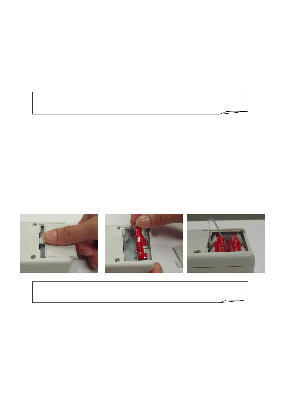
6. INSTALLING AND REMOVING BATTERY............................................................................. 5
7. SETTING OPERATION AND FUNCTION................................................................................ 6
7-1 SWITCHING STRAIN UNIT (F-1) ..................................................................................................... 6
7-2 STRAIN MODE................................................................................................................................... 6
7-3 MEAS MODE ...................................................................................................................................... 7
7-3-1 Calibration ................................................................................................................................................... 7
7-3-2 Preparation for Calibration ......................................................................................................................... 7
7-3-3 Load CAL (Actual Load Calibration F-2) .................................................................................................... 7
7-3-4 Sensitivity CAL (Sensitivity Registration Calibration F-3) ......................................................................... 7
7-3-5 Min Digit (Minimum Digit Scale F-4) .......................................................................................................... 8
7-3-6 AUTO-POWER OFF (F-5) ........................................................................................................................... 8
7-3-7 Digital ZERO ............................................................................................................................................... 8
7-3-8 PEAK HOLD ................................................................................................................................................ 8
8. TEDS FUNCTION ...................................................................................................................... 9
8-1 TEDS DATA SENSITIVITY REGISTRATION .................................................................................. 9
8-2 CALIBRATION FILE SENSITIVITY REGISTRATION ................................................................... 9
8-3 TEDS DATA SENSITIVITY REGISTRATION ................................................................................ 10
8-3-1 Setting TEDS Loading Operations (F-7) .................................................................................................... 10
8-4 CALBRATION FILE SENSITIVITY REGISTRATION .................................................................. 10
8-4-1 Creating Calibration File ........................................................................................................................... 10
8-4-2 Registering File (F-11) ................................................................................................................................11
9. FUNCTION SELECTING MODE SETTING LIST ................................................................. 12
10. ERROR CODE TABLE........................................................................................................... 14
11. SPECIFICATIONS.................................................................................................................. 15
12. EXTERNAL VIEW ................................................................................................................. 16

- 1 -
SAFETY PRECAUTIONS
PRIOR TO USE
This Manual describes detailed instructions for installing and setting up the WDS-180A Compact
Digital Indicator (hereinafter referred to as the WDS-180A).
For safe use of the WDS-180A, do not forget to read the ‘Safety Precautions’ prior to use.
KYOWA ELECTRONIC INSTRUMENTS CO., LTD. assumes no liability for any damages resulting
from user’s failure to comply with the safety precautions.
SAFETY SYMBOLS
For safety operation of the WDS-180A, the following ‘WARNING’ and ‘CAUTION’ symbols are used
in ‘Safety Precautions’ of this Instruction Manual.
WARNING
Improper operation of the system may result in death or severe injury of
the operator.
CAUTION
Improper operation of the system may result in injury of the operator and
physical damage of the system.
In addition, items in CAUTION may lead to serious consequences. Take special attention to the
Safety Symbols.
Safety Symbols
Indicates ‘Handling Precautions.’ This symbol is attached to the WDS-180A when it
requires to refer to the Instruction Manual for securing safety of the operator and the
product.
Indicates ‘Protective Ground Terminal.’ Always connect to ground before operating the
product.

- 2 -
WARNING
1) Installation and wiring work should be conducted more than 3 seconds after power OFF.
Or, electric shock hazard or damage of the product may result.
2) Special care should be taken not to use the WDS-180A in environment with inflammable
gas or vapor.
Or, fire hazard may result.
3) If the WDS-180A is faulty, emitting smoke or offensive odor, or producing abnormal sound,
immediately turn OFF the power. Or, electric shock or fire hazard may result. Contact
KYOWA or our representative for repair.
4) Do not put water or foreign matters into the WDS-180A. In case if any foreign matters are
entered, immediately turn OFF the power. Or, electric shock or fire hazard may result.
Contact KYOWA or our representative for repair.
5) Always operate the WDS-180A with batteries specified in this Instruction Manual.
Or, electric shock or fire hazard may result.
6) Do not operate the WDS-180A in environment with excessive moisture, dust or oil dust.
Or, electric shock or fire hazard may result
7) Do not disassemble the WDS-180A.
Or, deterioration or malfunction of the instrument may result.
CAUTION
1) Before wiring, always confirm the rated power voltage of the WDS-180A and terminal
arrangement. Then, conduct wiring in the correct manner.
2) Special care should be taken when using the WDS-180A in environment with excessive
vibration.
If the WDS-180A is operated at a location with excessive vibration or with continuous
vibration, it may cause measurement error and/or failure of the instrument. Take care not to
drop it during transportation and avoid applying strong impact.
3) Basically, the WDS-180A is designed to be used by connecting a strain gage transducer to
the input terminal.
When using the WDS-180A combined with other than the above, contact KYOWA or our
representative.
4) Operate the WDS-180A by conforming to operating environment specified in this
Instruction Manual. Or, malfunction and/or failure of the instrument may result.
5) When the all characters flicker, the battery is running low.
Immediately stop measurements and replace the battery with a new one. Or, it may cause
malfunction.

- 3 -
1. OUTLINE
The WDS-180A is a compact and lightweight digital indicator specified for strain gage transducers. The
WDS-180A is an indicator that not only displays physical quantity of the transducer but measures the
initial value of the transducer in [μm/m] or [mV/V] and conducts automatic sensitivity registration
when the Transducer Electronic Data Sheet (hereinafter referred to as the TEDS)-compatible transducer
is connected. The WDS-180A can be used in wide application such as for checking transducers and
simplified measurement.
2. FEATURE
○ Measures the original value (Unit: [μm/m] or [mV/V]) of the transducer by one-touch key operation.
○ Displays physical quantity using the Load CAL (Actual load calibration) and sensitivity registration
function.
○ When connecting the WDS-180A with the TEDS-compatible transducer automatically registers the
sensitivity and measures the data immediately after connection.
○ The WDS-180A is lightweight and pocketable enough for field works.
○ The WDS-180A can be used for long time by accessible 2 size AA batteries.
3. CONFIGURATIONS
WDS-180A Compact Digital Indicator 1
Size AA battery 2
Strap Installing Ring 1
Instruction Manual 1
Unit Seal 1
Calibration Sheet and Warranty 1

- 4 -
4. PARTS NAMES AND MAIN FUNCTIONS
1) Input Connector: ∙∙∙∙∙∙∙∙∙∙∙∙∙∙∙∙∙∙∙∙∙∙ Connects the strain gage transducer.
2) Power Switch: ∙∙∙∙∙∙∙∙∙∙∙∙∙∙∙∙∙∙∙∙∙∙∙∙∙∙ OFF: Turns the WDS-180A OFF.
STRAIN: Strain Measuring Mode
MEAS: Displays physical quantity converted data.
3) Indicator: ∙∙∙∙∙∙∙∙∙∙∙∙∙∙∙∙∙∙∙∙∙∙∙∙∙∙∙∙∙∙∙∙∙ Displays 4 digits numerical value.
4) →PEAK HOLD Key: ∙∙∙∙∙∙∙∙∙∙∙ Moves function No. , decimal point, or digit.
For PEAK HOLD operation.
5) ↑ZERO Key: ∙∙∙∙∙∙∙∙∙∙∙∙∙∙∙∙∙∙∙∙∙∙∙∙∙ Changes numeric value. Conducts ZERO.
To confirm function settings.
6) LED: ∙∙∙∙∙∙∙∙∙∙∙∙∙∙∙∙∙∙∙∙∙∙∙∙∙∙∙∙∙∙∙∙∙∙∙∙∙∙∙∙ Lights up when ZERO key is pressed.
7) SET Key: ∙∙∙∙∙∙∙∙∙∙∙∙∙∙∙∙∙∙∙∙∙∙∙∙∙∙∙∙∙∙∙∙ Sets and determines functions.
Note: Indicator flickers as follows.
Only all decimal point flickers Peak holding.
All character flicker The battery is running low.
Immediately replace the battery with a new one.
“-” of the left end symbols flickers In minus status.
1)
2)
All flickering:Battery exhausted
Flickering :Minus display
Decimals flickering:Peak measurement
PEAK
HOLD SET
COMPACT DIGITAL INDICATOR
ZERO
3)
4)
5)
6)
7)

- 5 -
Note:
Do not connect signals other than TEDS to the TEDS terminal. In addition, when
using
other than TEDS-compatible transducer, do not connect anything.
Or, it may cause troubles.
5. CONNECTING TRANSDUCER
•
Connect the transducer to
the
input connector.
•
Applicable connector: PRC03
-
12A10
-
7M10
(
TAJIMI ELECTRONICS
Co.,LTD.
mad
e)
•
Pin Nos. of the connector is as follows.
(Cables are separately colored based on typical KYOWA transducer cable.)
A: + side of the bridge excitation (Red)
B:
-
side of the bridge output (White)
C:
-
side of the bridge excitation (Black)
D: + side o
f the bridge output (Green)
E: Shield wire
F: TEDS (+)
G: TEDS (
-
)
•
Use as short as possible shield cable for wiring the transducer.
In addition, avoid locating the transducer from the wiring of electronic power system and
noisy cable.
•
The b
ridge excitation voltage of the WDS
-
180A is approximately 1 volt.
Check the
recommended applied voltage of the transducer is 1 volt or more.
6. INSTALLING AND REMOVING BATTERY
Push down and open the battery case cap on the WDS-180A rear.
Locate and correctly insert accessory or commercially available size AA batteries in the battery case
center band mentioned on the battery case.
Pull out the band to remove the batteries. Then batteries automatically come out.
• Battery continuous use time
(With 120 ohm transducer connected, when batteries are used with LED OFF at room temperature
25˚C)
Manganese battery: 24 hours or more
Alkaline battery: Approximately 100 hours
• To remind you to turn the WDS-180A OFF, setting the ‘Auto-Power OFF (F-5)’ is recom
mended.
The initial value is not set.
Note:
Customers are required to remove used batteries or batteries when not using the
WDS-180A for a long period of time. Or, batteries may leak and connection terminal
may corrode.

- 6 -
7. SETTING OPERATION AND FUNCTION
The WDS-180A is provided with ‘STRAIN Mode (STRAIN)’ that measures the actual output of the
strain gage transducer and ‘MEAS Mode (MEAS)’ that displays physical quantity by multiplying
coefficient.
7-1 SWITCHING STRAIN UNIT (F-1)
• The WDS-180A displays the output of the strain gage transducer in [μm/m] or [mV/V].
The unit is also used in the STRAIN mode and Sensitivity Calibration. Prior to use, set the unit to
either of [μm/m] or [mV/V].
• The setting can be changed by [F-1] mode.
Please check the switching method, see “9. FUNCTION SELECTING MODE SETTING LIST.”
Since the unit does not appear, use the accessory unit seal.
7-2 STRAIN MODE
Measures raw output of the strain gage transducer.
1) Power ON with the Power switch to set to ‘STRAIN.’
Displays the raw output of the strain gage transducer in [μm/m] or [mV/V].
The red LED lights up when power on if the ZERO is conducted before power off.
To cancel or shift the indicated value to ‘0,’ see the following item 2).
μm/m: An integer with no decimal point appears.
mV/V: A decimal point located in the 4th digit (.000) flickers.
2) Press the ZERO key to conduct the ZERO.
The red LED lights up and ‘0’ appears as the indicated value.
To cancel, press the ZERO key once again. The red LED lights out and the value shifted to ‘0’ is
cancelled.
The displayed value with the red LED OFF is the ‘Original value (Real output of the transducer.)’
3) Press the PEAK HOLD key to conduct the PEAK HOLD.
Decimal point positions of digits other than decimal point flickers and the maximum value appears.
To cancel, press the PEAK HOLD key once again. Flickering ends and the current value is
cancelled and cleared.
4) Usable functions in STRAIN mode
Only [F-1: Changing strain unit] and [F-5: Auto-Power OFF] can be used.
For setting procedures, see “9. FUNCTION SELECTING MODE SETTING LIST.”
Note: Even if the TEDS function is set, it does not operate in this mode.
Note: When the power is turned OFF, the PEAK HOLD measurement is cancelled.
Note: To confirm the function settings, press ZERO key to go back to the normal number display.
Pressing SET key in the function menu is not enough to confirm function settings.

- 7 -
7-3 MEAS MODE
Converts the output of the strain gage transducer to the physical quantity and displays the converted
data.
7-3-1 Calibration
Registers the conversion coefficient for displaying the transducer output in physical quantity.
It is essential to conduct either the ‘Load CAL (Actual Load Calibration)’ or ‘Sensitivity CAL
(Sensitivity Registration Calibration).’
7-3-2 Preparation for Calibration
• Connecting Transducer: Connect the strain gage transducer.
• Power ON: Set the Power switch to ‘MEAS.’
• Conducting ZERO:With no load applied to the transducer, press the ZERO key.
7-3-3 Load CAL (Actual Load Calibration F-2)
Actually applies the existing load and calibrates the transducer.
•
Loading:
Applies the existing load to the transducer.
•
Function:
Press the
SET
key
to
display [F
-
1].
•
Load CAL
(Actual Load Calibration):
Press the
→
key to display [F
-
2].
•
Rated capacity:
Press the
SET
key to display
the preset value.
Press the → and ↑ keys to set the applied load value by ignoring the
decimal point.
Press the
SET
key.
•
Decimal point setting:
Press the
↑
key to move the decimal point.
Press the
SET
key.
•
Setting Ends:
[F
-
2] appears
. Press the
ZERO
key to return to the measuring state.
7-3-4 Sensitivity CAL (Sensitivity Registration Calibration F-3)
Registers and calibrates the ‘Rated Output and Rated Capacity’ of the transducer.
•
Function:
Press the
SET
key
to
display [F
-
1].
•
Sensitivity CAL
(Sensitivity Registration
Calibration):
Press the
→
key to display [F
-
3].
•
Rated Output:
Press the
SET
key to display the preset value.
μ
m/m:
An integer with no decimal point appears.
mV/V:
A
decimal
point in the 4th digit flickers.
Press the → and ↑ keys to set values in the Calibration Sheet.
Press
the
SET
key.
•
Rated Capacity:
Press the
SET
key to display the preset value.
Press the → and ↑ keys to set the Calibration Sheet value by ignoring
the decimal point.
Press the
SET
key.
•
Decimal Point Setting:
Press the
↑
key to move the decimal point.
Press the
SET
key.
•
Setting Ends:
[F
-
3] appears
. Press the
ZERO
key to return to the measuring state.
Note:
When conducting the Calibration, be sure to conduct the
ZERO
.

- 8 -
Note: When the setting time is ‘00’ minute, Auto-Power OFF does not activate.
7-3-5 Min Digit (Minimum Digit Scale F-4)
Makes the indication stable and offers easy-to-read display.
The Min digit (Minimum digit scale) of the indicated value appears in every 1, 2, or 5 step.
• Function: Press the SET key to display [F-1].
• Min Digit
(Minimum Digit Scale):
Press the →key to display [F-4].
Press the SET key. The selected value appears and flickers.
Press the ↑key. Select and set from the 1, 2, and 5 steps.
Press the SET key.
• Setting Ends: [F-4] appears. Press the ZERO key to return to the measuring state.
7-3-6 AUTO-POWER OFF (F-5)
Prevents wasting of battery power when you forget to turn OFF the power. Automatically turns OFF the
power after the preset time from the last key operation. Setting Range: 00 to 99 minutes
• Function: Press the SET key to display [F-1].
• Auto-Power OFF: Press the →key to display [F-5].
Press the SET key. The set value appears and flickers.
Press the ↑and →keys. Select and set from the 00 to 99.
Press the SET key.
• Setting Ends: [F-5] appears. Press the ZERO key to return to the measuring state.
7-3-7 Digital ZERO
Shifts the indicated value to ‘0.’
• To conduct the ZERO, press the ZERO key.
• The red LED lights up and ‘0’ appears as the indicated value.
• To cancel, press the ZERO key once again. The LED lights out and the ZERO is canceled.
7-3-8 PEAK HOLD
Displays maximum value.
• Press the PEAK HOLD key to conduct the PEAK HOLD.
• Decimal point positions of digits other than the decimal point flicker and display the maximum
value.
• To cancel, press the PEAK HOLD key once again. Flickering ends and the PEAK HOLD is
cancelled.
Note: The PEAK HOLD is cancelled when the power is turned OFF.

- 9 -
8. TEDS FUNCTION
By connecting with the TEDS-compatible transducer, automatically conducts the Sensitivity CAL
(Sensitivity registration calibration).
There are ‘TEDS Data Sensitivity Registration’ and ‘Calibration File Sensitivity Registration.’
8-1 TEDS DATA SENSITIVITY REGISTRATION
Loads the rated capacity and rated output from the transducer TEDS data, automatically conducts the
Sensitivity CAL (Sensitivity registration calibration), also calculates the decimal point position and
displays the physical quantity.
Set the transducer to be in no load state as same as when conducting Sensitivity CAL (Sensitivity
registration calibration). Conduct TEDS loading to conduct the Sensitivity CAL (Sensitivity registration
calibration). The TEDS loading operation is set with the ‘F-7’ setting. When the ‘Conducting ZERO
after the TEDS operation’ is set to ‘0: Conduct’, after the Sensitivity CAL (Sensitivity registration
calibration), the WDS-180A conducts ZERO to display ‘0.’ Then, the measurement can be started
immediately.
8-2 CALIBRATION FILE SENSITIVITY REGISTRATION
Loads the serial No. from the transducer TEDS data, selects the same serial No. file from the
WDS-180A inner saved calibration file and automatically sets the rated output, rated capacity, decimal
point position, zero value and minimum scale when registering the sensitivity.
When converting and using the transducer capacity or when obtaining initial zero is not available due to
the applied load, by using the already registered calibration data, the measurement can be easily
conducted.
1) Conducting TEDS loading
Conduct TEDS loading in the following procedure.
• TEDS Key Operation: Press PEAK HOLD and ZERO keys at the same time.
• If ‘---’ appears, press PEAK HOLD and ZERO keys.
• ‘ld’ appears and automatically sets the sensitivity registration calibration.
• Automatically conducts TEDS loading when power ON:
Capable by Setting TEDS loading operation [F-7].
2) Selecting TEDS function (F-10)
Sets TEDS function in the ‘TEDS Data Sensitivity Registration’ or ‘Calibration File Sensitivity
Registration.’
• Function: Press the SET key to display [F-1].
• Calibration File Operation: Press the →key to display [F-10].
Press the SET key.
The preset value appears.
0: ‘TEDS Data Sensitivity Registration’
Registers the sensitivity by the transducer TEDS data.
1: ‘Calibration File Sensitivity Registration’
Registers the sensitivity by the Calibration file.
Press and set with the ↑key.
Press the SET key.
• Setting Ends: [F-10] appears. Press the ZERO key to return to the measuring
state.

- 10 -
8-3 TEDS DATA SENSITIVITY REGISTRATION
The TEDS data sensitivity registration is an automatic sensitivity registration function which
automatically sets the ‘rated output, rated capacity and decimal point’ by loading the TEDS data. Set the
loading operation in the following procedure.
8-3-1 Setting TEDS Loading Operations (F-7)
Conduct or prohibit the following functions.
For setting procedures, see “9. FUNCTION SELECTING MODE SETTING LIST.”
1) TEDS operation when power ON
When power ON in MEAS mode, automatically loads the TEDS data.
The initial value is set to ‘1: Prohibit.’
2) Conducting ZERO after the TEDS operation
When conducting the ‘TEDS loading,’ conducts ZERO to display ‘0.’
The initial value is set to ‘1: Prohibit.’
3) Rated output and rated capacity
Sets the loading execution and loading prohibition to the respective rated output and rated capacity.
The initial value is set to ‘0: Conduct.’
8-4 CALBRATION FILE SENSITIVITY REGISTRATION
By using the serial No. from the data obtained by the TEDS data loading, call up the same serial No.
calibration file from the saved calibration file (Maximum 32 files) saved in the WDS-180A and
automatically registers the rated output, rated capacity, decimal point, zero value, and Min digit when
registering the sensitivity.
8-4-1 Creating Calibration File
Set the calibration value to the WDS-180A to conduct correct measurement.
•
Connect the TEDS
transducer.
•
With no load applied to the transducer, press the
ZERO
key to display
‘
0
.’
•
Change and set the calibration value by loading the
‘
TEDS Data Sensitivity Registration
’
or by the
Load CAL (Actual load calibration) or Sensitivity CAL (Sensitivity registration calibration)
functions. In addition, set the minimum scale as required.
For setting procedures, see “8-3 TEDS DATA SENSITIVITY REGISTRATION” and “7-3 MEAS
MODE.
”
Note 1: The digital zero conducted at the TEDS operation is the standard point and is
equally regarded as the calibrating zero.
Note 2: When rated output and rated capacity are set to ‘1: Prohibit,’ the previously loaded
value (Registered in the F-3) is used for calculation.
Reference:
By using this function, the measurement can be conducted with ease when the
rated capacity unit is converted or when conducting ZERO is not available.

- 11 -
8-4-2 Registering File (F-11)
Currently set calibration value and set value are saved in the file No. (1 to 32) by the ‘Operating
Calibration File’ (F-11.)
Contents of the above saved items are Serial No., rated capacity, rated output, decimal point, zero value,
and Min digit.
(Clearing file is also conducted with this function.)
• Function: Press the SET key to display [F-1].
• Calibration File Operation: Press the →key to display [F-11].
Press the SET key.
Preset status ‘1), 2), 3), and 4)’ appear.
1) Tenth digit of the file No. (0 to 3)
2) First digit of the file No. (1 to 9)
3) Presence or absence of data (Display only)
0: Absence
1: Presence
4) File Registration
0: Stop
1: Register (When the above 3)=0)
2: Overwrite (When the above 3)=0 and 1)
3: Clear
Press the →and ↑keys to set digits.
Press the SET key.
• Ends Setting: [F-11] appears.
Press the ZERO key to return to the measuring state.
Registering the same serial No. is prohibited. When the serial No. is already registered, the file No.
flickers. At this time, clear the flickering file No. to register.
Note 1: When the zero value of this file is set as standard, be sure to set the Setting TEDS
Loading Operations to ‘1: Prohibit.’
When ‘2: Conduct’ is selected, ‘0’ appears.
Note 2: The WDS-180A can not connect multiple TEDS transducers at the same time.
Displays error and no TEDS function is conducted.
Note 3: For details of each error, see “10. ERROR CODE TABLE.”

- 12 -
9. FUNCTION SELECTING MODE SETTING LIST
•
Press the
SET
key more than 3 seconds in
the mea
suring state. [F
-
1] appears
to activate the
function selecting mode.
•
For changing the function, press the
→
key to display the target mode.
•
Pressing the
SET
key displays setting contents.
•
After changing the setting contents (Displaying [F
-
*]), press the
ZERO
key to return to the
measuring state.
Mode
Key Operation and Movement
Description
F
-
1
Changing Strain Unit
(Initial Value: μm/m)
Every time the
→
key is pressed, the
unit switches.
μ
m/m
Displays with no
decimal
point.
mV/V
Displays the decimal point at the
4th digit (.000).
After determine the unit, press the
SET
key.
•
Set output unit of th
e
transducer.
[μm/m]/[mV/V]
• The display flickers with
the original value.
F
-
2
Load CAL
(Actual Load
Calibration)
Press the
→
and
↑
keys to set the
applied load value by ignoring the
decimal point.
Press the SET key.
Press the ↑key to move the decimal
point.
Press the SET key.
•
Calibrates the transducer by
using the actual load.
Prior to conduct the Load
CAL (Actual load
calibration),
• Set the transducer to be in
no load state and press
ZERO key to display ‘0.’
• Apply the existing load to
the
transducer.
F
-
3
Sensitivity CAL
(Sensitivity
Registration
Calibration)
(Initial Value:
9000 μm/m
9000 display
with no decimal point)
•
The rated output (Set value)
appears in [μm/m] or [mV/V].
Press the →and ↑keys to set the
rated output of the Calibration
Sheet.
Press the SET key.
• The rated capacity (Set value)
appears.
Press the →and ↑keys to set the
rated capacity of the Calibration
Sheet by ignoring the decimal
point.
Press the SET key.
• The decimal point (Preset value)
appears.
Press the ↑key to move the
decimal point.
Press the
SET
key.
•
Set the rated output and
rated capacity of the
transducer to calibrate
the transducer.
Prior to conduct the
Sensitivity CAL (Sensitivity
registration calibration),
• Set the transducer to be in
no load state and press
ZERO key to display ‘0.’
F
-
4
Min Digit
(Minimum Digit Scale)
(In
itial Value: 1)
The set value appears
and flickers.
Press the ↑key and set desired digit,
1, 2, or 5.
Press the
SET
key.
•
Stables the indication when
the Min Digit (Minimum
digit scale) is unstable.
F
-
5
Auto-Power OFF
(Initial Value: 00)
The preset value appears
and flickers.
Press the →and ↑keys. Select and
set from 00 to 99.
Press the SET key.
•
Function that reminds you
to turn OFF the power.
• When 00 appears, the
Auto-Power OFF does
not activate.

- 13 -
Mode
Key Operation and Movement
Description
F
-
7
Setting TEDS
Loading Operation
(Initial Value: 1100)
S
tatus
of 1), 2), 3), 4) appear
and changing
digit flickers.
Press the →and ↑keys to set.
1)TEDS operation when power ON
0: Conduct 1: Prohibit
2)Conducting the ZERO after the TEDS
operation
0: Conduct 1: Prohibit
3)Rated Output 0: Conduct 1: Prohibit
4)Rated Capacity 0: Conduct 1: Prohibit
Press the SET key.
•
Set TEDS
loading
operation.
F
-
10
Selecting TEDS
Function
(Initial Value: 0)
Preset value appears
.
0:
Sensitivity Registration by
transducer TEDS data.
1:
Sensitivity Registration
by
calibration file
Press the
SET
key.
•
Select the TEDS
function.
F
-
11
Operating
Calibration File
(Initial Value: 0100
~3200)
Status
of 1), 2), 3), 4) appeare
.
Press the →and ↑keys to specify the
calibration file No. and conduct file
operation.
1)
Tenth digit of the calibration
file No.
0 to 3
2)
First digit of the calibration
file No.
0 to 9
3)
Presence or
absence
o
f
data
(Display
only)
0:
Absence
1: Presence
4)
File Registration
0: Stop
1: Register
(When the above 3)=0)
2:
Overwrite
(When the above 3)=0 and 1)
3: Clear
Press the
SET
key.
•
Specify the desired file
No. (1 to 32) and save the
serial No., rated capacity,
rated output, decimal point,
zero value, and Min digit to
the internal memory.
Note: When conducting the
[Register] and
[Overwrite] without
connecting the TEDS
sensor, the [ldEr]
appears.
PEAK
HOLD SET
ZERO
Note: To confirm the function settings, push ZERO key to go back to the normal number display.
Pressing SET key in the function menu is not enough to confirm function settings.

- 14 -
10. ERROR CODE TABLE
Error message Contents Countermeasures
IdEr Failed to communicate with a
TEDS-compatible sensor.
Make sure TEDS-compatible sensors
are connected.
noEr The serial No. (****) does not exist. Make sure serial Nos. are correct.
oL The indicating value is exceeding the
input range.
Exceeding the input range.
Use the input signal within ±5mV/V.
Ad Sensor cables are not connected. Make sure wirings are correct.
Err Calibration constants are incorrect.
Make sure the E value sensitivity is
×10 to ×0.01 (excluding decimal
point) against input strains (µm/m).
Er02 The target file has data. Clear (3) or overwrite (2) the data.
Er03 Failed to calibrate TEDS data. TEDS data is incorrect.
Do not use TEDS data.
Er00 Failed to load data files or incorrect
data.
If the same error message appears,
contact Kyowa or our
representatives.
When requesting repair, always give
error statuses and error messages.
Er01 Failed to write EEPROM while saving
data files.
Er04 Failed to write EEPROM while
overwriting data files.
Er06 Failed to write EEPROM while clearing
data files.
EP0 to EP7 EEPROM area is not working properly.
Failure
Contact Kyowa or our
representatives.
When requesting repair, always give
error statuses and error messages.

- 15 -
11. SPECIFICATIONS
Applicable Transducer ∙∙∙∙∙∙∙∙∙∙∙∙∙∙∙∙∙∙∙∙ Strain Gage Transducer with full bridges
Input Resistance: 60 to 1000 ohm
Bridge Excitation ∙∙∙∙∙∙∙∙∙∙∙∙∙∙∙∙∙∙∙∙∙∙∙∙∙∙∙∙ Approximately 1 VDC (Constant)
Input Range ∙∙∙∙∙∙∙∙∙∙∙∙∙∙∙∙∙∙∙∙∙∙∙∙∙∙∙∙∙∙∙∙∙∙∙∙ ±10000 μm/m (±5.0 mV/V) including zero adjustment range
Strain: Within ±9999 μm/m
Sampling ∙∙∙∙∙∙∙∙∙∙∙∙∙∙∙∙∙∙∙∙∙∙∙∙∙∙∙∙∙∙∙∙∙∙∙∙∙∙∙∙∙ Approximately 3 times/sec
Sensitivity Registering Function ∙∙∙∙∙ Load CAL (Actual Load Calibration)
Sensitivity CAL (Sensitivity Registration Calibration)
TEDS CAL
TEDS Function ∙∙∙∙∙∙∙∙∙∙∙∙∙∙∙∙∙∙∙∙∙∙∙∙∙∙∙∙∙∙∙ TEDS Data Sensitivity Registration
Calibration by loading the data of TEDS-compatible
transducer.
Calibration File Sensitivity Registration
Calibration by the inner saved Calibration file.
Zero Function ∙∙∙∙∙∙∙∙∙∙∙∙∙∙∙∙∙∙∙∙∙∙∙∙∙∙∙∙∙∙∙∙∙∙ Conducts digital zero within the input range
Display ∙∙∙∙∙∙∙∙∙∙∙∙∙∙∙∙∙∙∙∙∙∙∙∙∙∙∙∙∙∙∙∙∙∙∙∙∙∙∙∙∙∙∙∙ 7-segment type LCD
-9999 to 9999
Display accuracy∙∙∙∙∙∙∙∙∙∙∙∙∙∙∙∙∙∙∙∙∙∙∙∙∙∙∙∙∙∙ ±(0.05%rdg +5digit) μm/m
Display Switching Function ∙∙∙∙∙∙∙∙∙∙∙∙ μm/m or mV/V
Mode ∙∙∙∙∙∙∙∙∙∙∙∙∙∙∙∙∙∙∙∙∙∙∙∙∙∙∙∙∙∙∙∙∙∙∙∙∙∙∙∙∙∙∙∙∙∙∙ STRAIN Mode: Displays either unit [μm/m] or [mV/V].
MEAS Mode: Displays physical quantity by using the
calibration function.
Min Digit (Minimum Digit Scale) ∙∙∙ 1, 2, and 5 steps selectable. (When in MEAS mode)
PEAK HOLD ∙∙∙∙∙∙∙∙∙∙∙∙∙∙∙∙∙∙∙∙∙∙∙∙∙∙∙∙∙∙∙∙∙∙ Digitally maintains the maximum value during the measurement.
Auto-Power OFF ∙∙∙∙∙∙∙∙∙∙∙∙∙∙∙∙∙∙∙∙∙∙∙∙∙∙∙∙∙ Set to ‘1 to 99’ minutes or ‘00.’
Operating Temperature Range ∙∙∙∙∙∙∙∙∙ -5 to 40˚C
Operating Humid Range ∙∙∙∙∙∙∙∙∙∙∙∙∙∙∙∙∙∙ 20 to 85% RH (Non-condensing)
Battery ∙∙∙∙∙∙∙∙∙∙∙∙∙∙∙∙∙∙∙∙∙∙∙∙∙∙∙∙∙∙∙∙∙∙∙∙∙∙∙∙∙∙∙∙ Size AA battery: 2
Operating Time ∙∙∙∙∙∙∙∙∙∙∙∙∙∙∙∙∙∙∙∙∙∙∙∙∙∙∙∙∙∙∙ Continuously approximately 24 hours
(With 120 ohm transducer connected, when manganese batteries
are used with LED OFF at room temperature 25˚C)
Dimensions ∙∙∙∙∙∙∙∙∙∙∙∙∙∙∙∙∙∙∙∙∙∙∙∙∙∙∙∙∙∙∙∙∙∙∙∙∙ 66.5 (W) × 92 (H) × 28 (D)
Protruded portion not included
Weight ∙∙∙∙∙∙∙∙∙∙∙∙∙∙∙∙∙∙∙∙∙∙∙∙∙∙∙∙∙∙∙∙∙∙∙∙∙∙∙∙∙∙∙∙∙ Approximately 180 g
Optional ∙∙∙∙∙∙∙∙∙∙∙∙∙∙∙∙∙∙∙∙∙∙∙∙∙∙∙∙∙∙∙∙∙∙∙∙∙∙∙∙∙∙ Voltage Monitor Output Terminal

- 16 -
12. EXTERNAL VIEW
!DANGER
1.Do Not apply
heat or throw in-
to fire.
2.Do Not connect
battery plus &mi-
nus to metals.
MEAS
STRAIN
OFF
All flickering:Battery exhausted
Flickering :Minus display
Decimals flickering:Peak measurement
PEAK
HOLD SET
COMPACT DIGITAL INDICATOR
ZERO
F-1:μm/m mV/V
F-2:Load CAL
F-3:Sensitivity CAL
F-4:Min Digit 1,2,5
F-5:Auto-Power OFF
F-7:Setting TEDS Loading Operation
Press 2 sec Change F Settings
SET SET
Note:only F1/F5 can be used,if it's STRAIN MODE
Ser. MADE IN JAPAN
Back
SET
WDS-180A Setting Function
F-10:Selecting TEDS Function
F-11:Operating Calibration File
92
66.528

- 17 -
Table of contents
Other KYOWA Measuring Instrument manuals
Popular Measuring Instrument manuals by other brands

Hach
Hach POCKET COLORIMETER II LCK 325 Application Instruction

Spectrum Techniques
Spectrum Techniques fieldscout TDR 100 product manual

Alnor
Alnor 275 owner's manual

KARL DEUTSCH
KARL DEUTSCH ECHOMETER 1077.080-A operating instructions

Greenlee
Greenlee CM-600 instruction manual

CodaOctopus
CodaOctopus F180R Series User reference guide

Chauvin Arnoux
Chauvin Arnoux PAC 20 user manual

PCE Health and Fitness
PCE Health and Fitness PCE-WL 2 user manual

Field Scout
Field Scout TDR 350 product manual

Aquaread
Aquaread AquaTelemetry instruction manual

PCB Piezotronics
PCB Piezotronics IMI Sensors TO625B01 Installation and operating manual

Vega
Vega VEGABAR 54 operating instructions