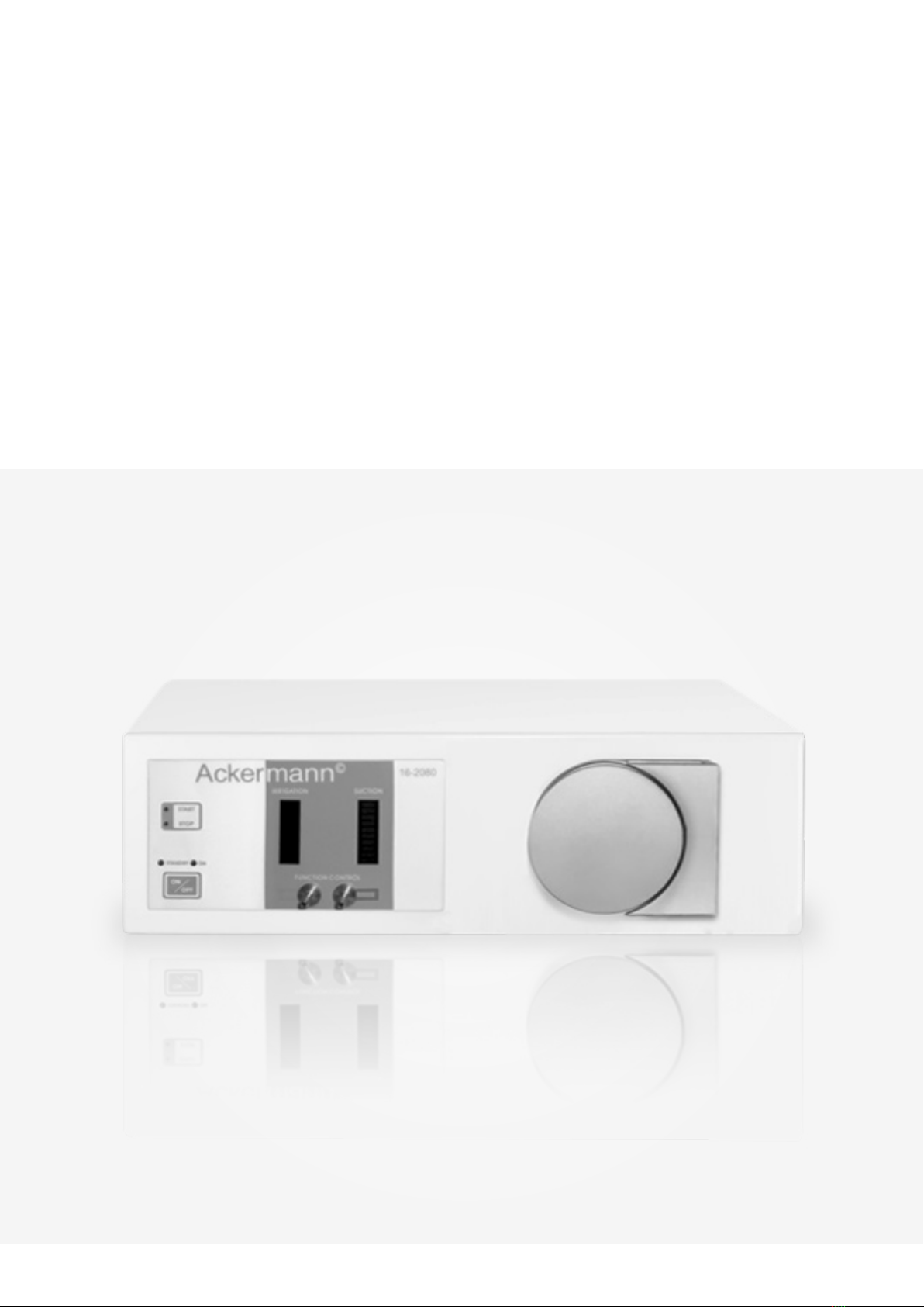
DOUBLE ROLLER PUMP FOR LAPAROSCOPY
Page: 6 // 18
•Liabilitymaybevoidedbymisuse,abuse,violationofinstructionsforuse,omissionofrequiredmaintenance,opening
theequipmentmodications,repairsbyunauthorizedpersons!Useofotherthanoriginalaccesaccessoriesshallvoid
warranty and liability.
•Equipmenthastobeusedatalltimesinaccordancewiththeoperatinginstructions!
ThisdevicecomplieswithcurrentlyvalidEMVstandards.HowevertestsofEMVstandardDINEN60601-1-2:1993-05are
carried out. Nevertheless, EMV interference may lead to malfunctioning. If malfunctioning is observed, ensure that the
device has been installed and is being operating in accordance with EMV guidelines for use supplied with the device. Note
thatportableandmobilehigh-frequencycommunicationequipmentmay inuencetheoperation ofthisdevice. If the
device is used in the vicinity of or stacked together with other devices, the device or system must be monitored to ensure
standard use in accordance with these guidelines. If necessary, notify the manufacturer of the corresponding details.
IMPORTANT! Incaseoffailureswitchoffthedeviceatitsmainpowerswitch(1).Pullmainsconnection.
Do not open the unit. No user-servicable parts inside.
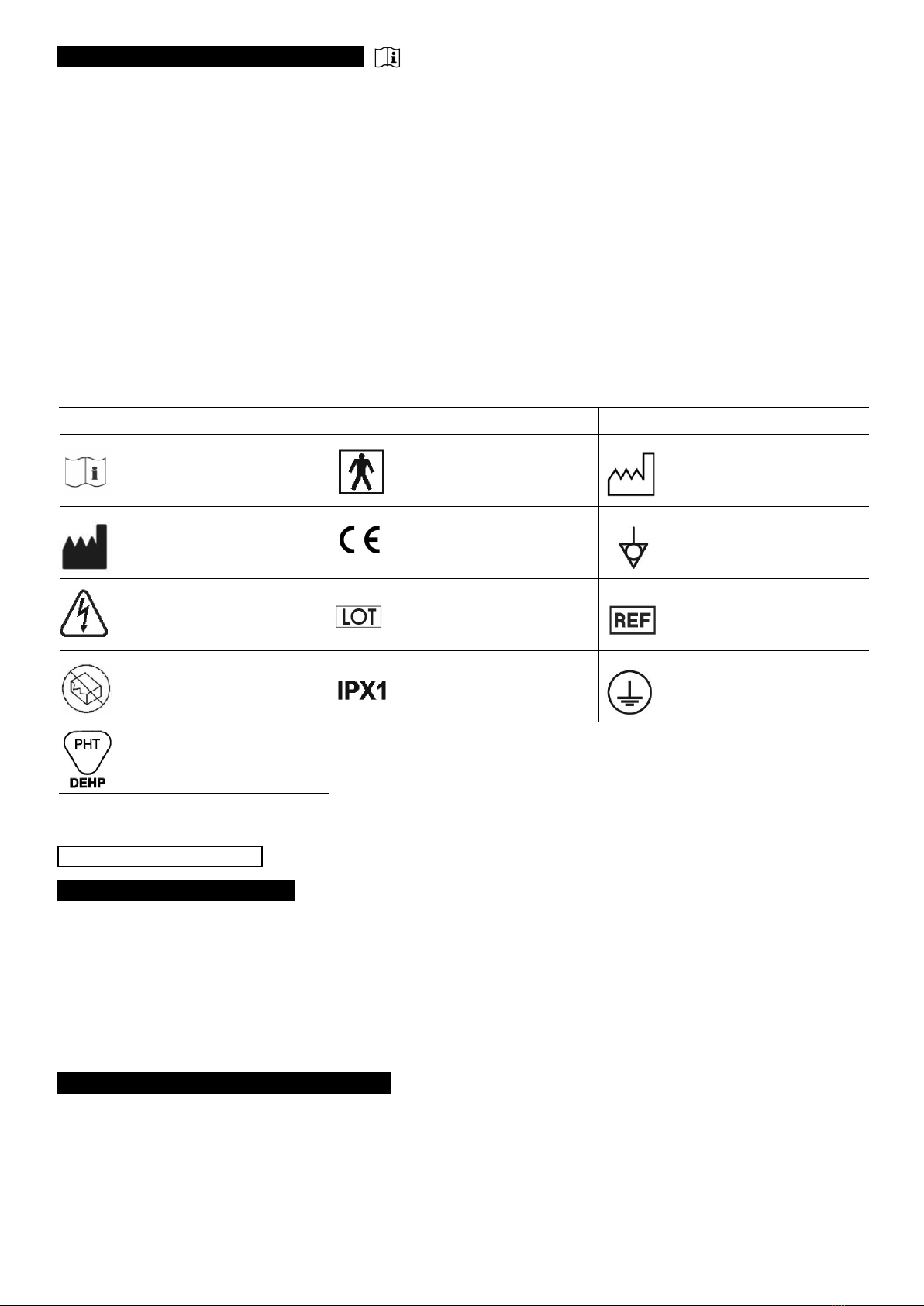
Symbol and description Symbol and description Symbol and description
Follow the instructions for use Type BF applied part Year of production
Legal manufacturer
mdcmedicaldevicecerticationGmbH,
Kriegerstraße 6,
70191Stuttgart,Germany
Equipotential
(equalisingpotential)
C a u t i o n!
Hazardous voltage Batch number Article number
Do not use if package is
damaged
Spray protection (protection
againstverticallyfallingdrops) Protective earthing
Product contains phthalate
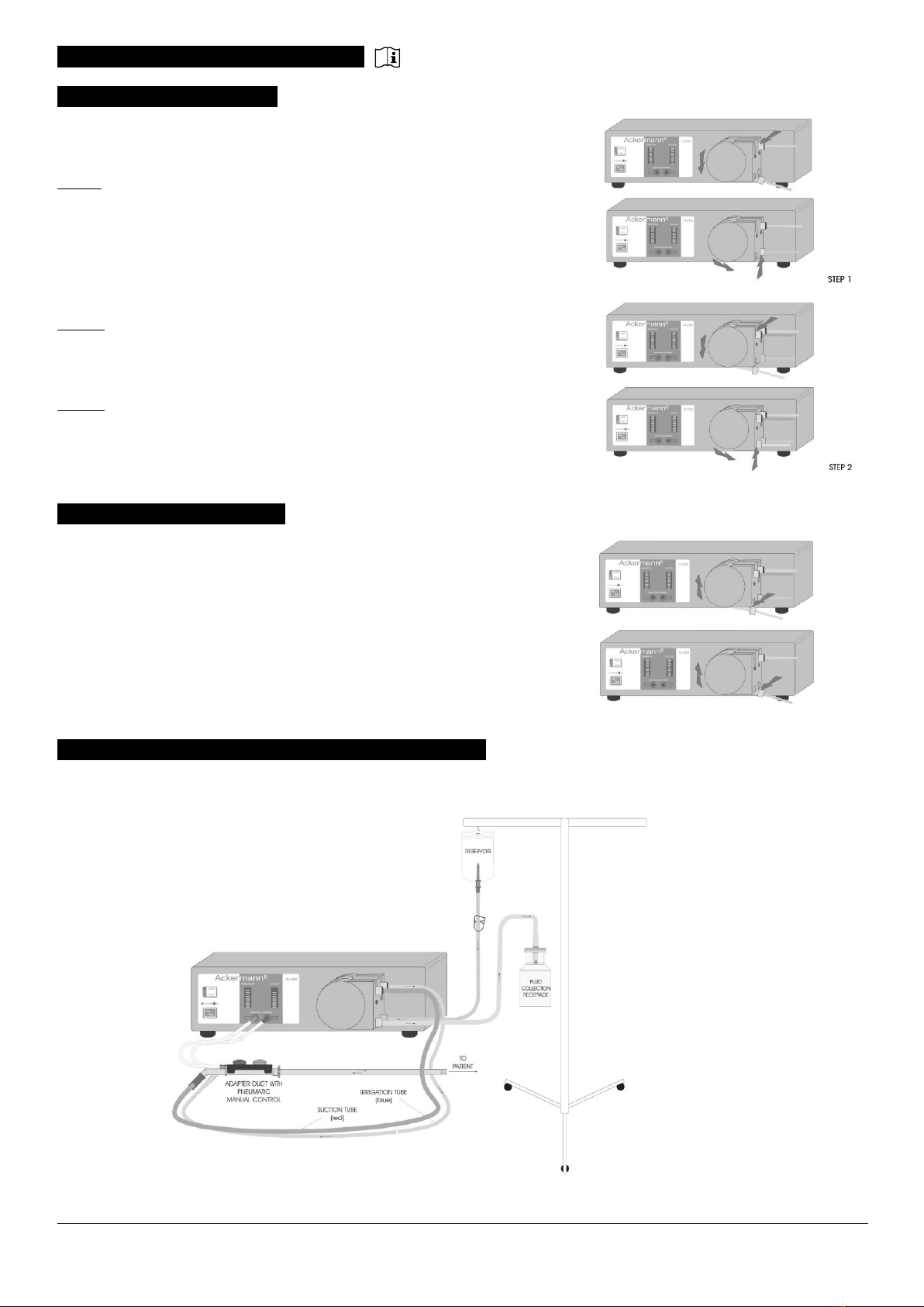
The tube set comprises two separate, color-coded tubes.
Thebluetubeisusedforirrigationandtheredoneforsuction.Bothtubesarettedwithcoloredrings(blueandred).
Youwillndacoloredringattubestopperofpumpsegment,seesection6.3.
Toinsertthecorrecttubesyouwillndcorrespondingcolor-codingonthedevice’stubeholderinblueandred.
All components of the reusable tube set can be autoclaved at a maximum temperature of 134°C and pressure of 2 bar.
Thetubesetcanbedismantled(seesection6.3.),butmustbecompletelyreassembledanddriedbeforesterilization.
IMPORTANT! Whenttingtogetherthetubeset,pleaseensurethatthereisatight,leak-proofconnectionbetweenthe
adapter and the tube sections.
0483