ACO PS4515-PRO-13 User manual

GENERAL INFORMATION
Power supply unit with a built-in video splitter for up to 3 monitors (MPRO 4, 3.5, or GLASS-PRO- ), dedicated
to COMO / Familio PRO system. Typically used in single family, two or three family houses, to supply the entire Typically
used in single family, two or three family construction, to supply the entire video intercom system. The power supply units
can be combined with each other and used also in multi-family houses. It can also be used to connect UPRO audio
receivers (for PRO and PRO-A systems). The power supply unit is also compatible with other ACO audio/video systems. It
can be connected with RJ-45 connectors or, alternatively, with ARK screw connectors.
Features:
- connection of 3 monitors at a distance of up to 0 m (cat. 5e)
- main input from a panel or another ACO standard source
- direct connectivity of a COMO/ Familio PRO panel at a distance of up to 100 m (cat. 5e, with no E-lock supply)
- E-lock supply availability (only with ARK screw connectors)
- built-in, active video amplifiers
- compatible with other ACO video systems
- connectivity with RJ-45 or ARK screw connectors
- DIN rail mounting
TECHNICAL PARAMETERS
•Power supply voltage 100 – 240 VAC 1.0 A 50 / 60 Hz
•Output voltage 15 VDC ± 5%
•Allowable load current 3 A
•Mounting DIN rail 35 mm or surface mounted
•Width 6 DIN modules (106.3 mm)
•Installation type (Video version) digital PRO / PV system: twisted pair cat. 5e or 6
•Installation type (Audio version) digital PRO-A system: 3 wires
•Outputs ARK screw connectors (disconnectable): 15 V DC, GND,
Line, 3 x video (differential); 3 x RJ45 to connect monitors
•Inputs ARK screw connectors (disconnectable): 230 V (PE, L, N),
Video IN (differential); 1 x RJ45 to connect COMO/Familio
PRO panel (with no E-lock supply)
SYSTEM ASSEMBLY AND CONNECTION
ATTENTION! For proper performance and safety of use, the power supp y unit shou d be connected to
230 V mains with a suitab e three-core cab e, abso ute y connecting the PE termina . The connection to the 230 V
mains must be made by a qua ified e ectrician - the vo tages there are dangerous for hea th and ife!
The power supply unit is intended for mounting on a 35 mm DIN rail or surface mounting. Connections should be
made with dedicated plugs to screw and RJ45 connectors as shown in Fig. 1.1 and 1.2.
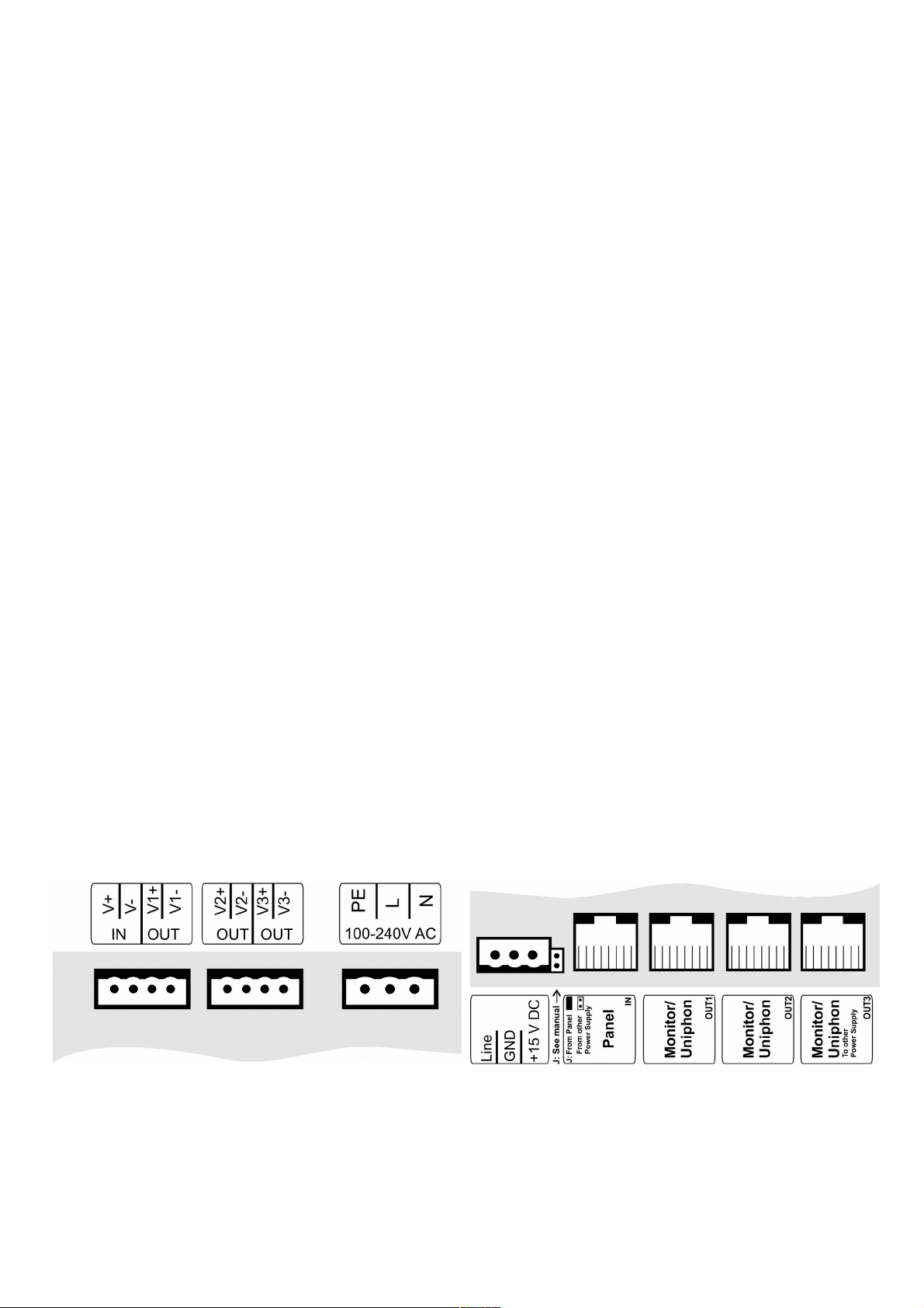
Fig. 1.1. Outputs at the power supply unit's top Fig. 1.2. Outputs at the power supply unit's bottom
The mains supply shall be connected to a 230 V AC plug, paying attention to the correct connections of the phase and the
neutral conductors.

With a RJ45 connector, the twisted pair should be tightened as shown in Fig. 3, the monitor should be connected to output
1, 2 or 3, and the panel should be connected to the input. With screw connectors, they shall be connected as per Fig. 4:
power supply to terminals + 15 V DC and GND, audio/ data signal line to LINE terminal, video respectively to terminals: IN
(V + and V-) from Panel, OUT (V1-, V1 +, etc.) to individual monitors. Operation is not allowed with a RJ45 connector and
a screw connector in the same video channel at the same time. The + 15 V DC and GND output voltage can supply the E-
lock (EL POW + and EL POW-) in the panel.
To interconnect multiple power supply units, Output 3 (OUT3) should be connected to Input (IN) of another unit.
ATTENTION! No voltage (+ 15 VDC) connection to different power supply units can be allowed. To do this, disconnect
power supply from IN connector (Panel) by removing jumper J (if RJ45 connectors are used) or by not connecting + 15
VDC power supply wires (orange and brown) to ARK screw connector.
It is recommended to make the connections with an unshielded twisted pair (UTP) of at least 5e or 6 category, and to
connect E-lock power supply with conductors of at least 1.5 mm2, maintaining the distance as per Fig. 2.
Fig. 2. Basic details of line lengths and wire types
Comments:
1) The distance for cat. 5e cable, can be extended by increasing the wires' cross-section (e.g. cat. 6e or by adding a
thicker wire for signals: Line, GND, + DC). To connect the panel at a distance over 100 m, an additional 15 VDC power
supply unit should be connected directly to the Panel.
2) UTP cat. 5e twisted par is required for proper video transmission, image distortion may occur if other cable types are
used.
3) E-lock power supply
1) 2) 3) If the system is connected with a wire other than recommended or the distances are larger than those specified,
the installation is possible, but a test connection of the set-up should be made, and the whole system's performance
should be checked. Also the technical support can be contacted at www.aco.com.pl or by email to [email protected].pl
Routing the video door entry system cables (especially those for Audio/Video signals) in close proximity of another wiring
(power, telecommunications, alarm systems) should be avoided, as this can adversely affect the system performance.
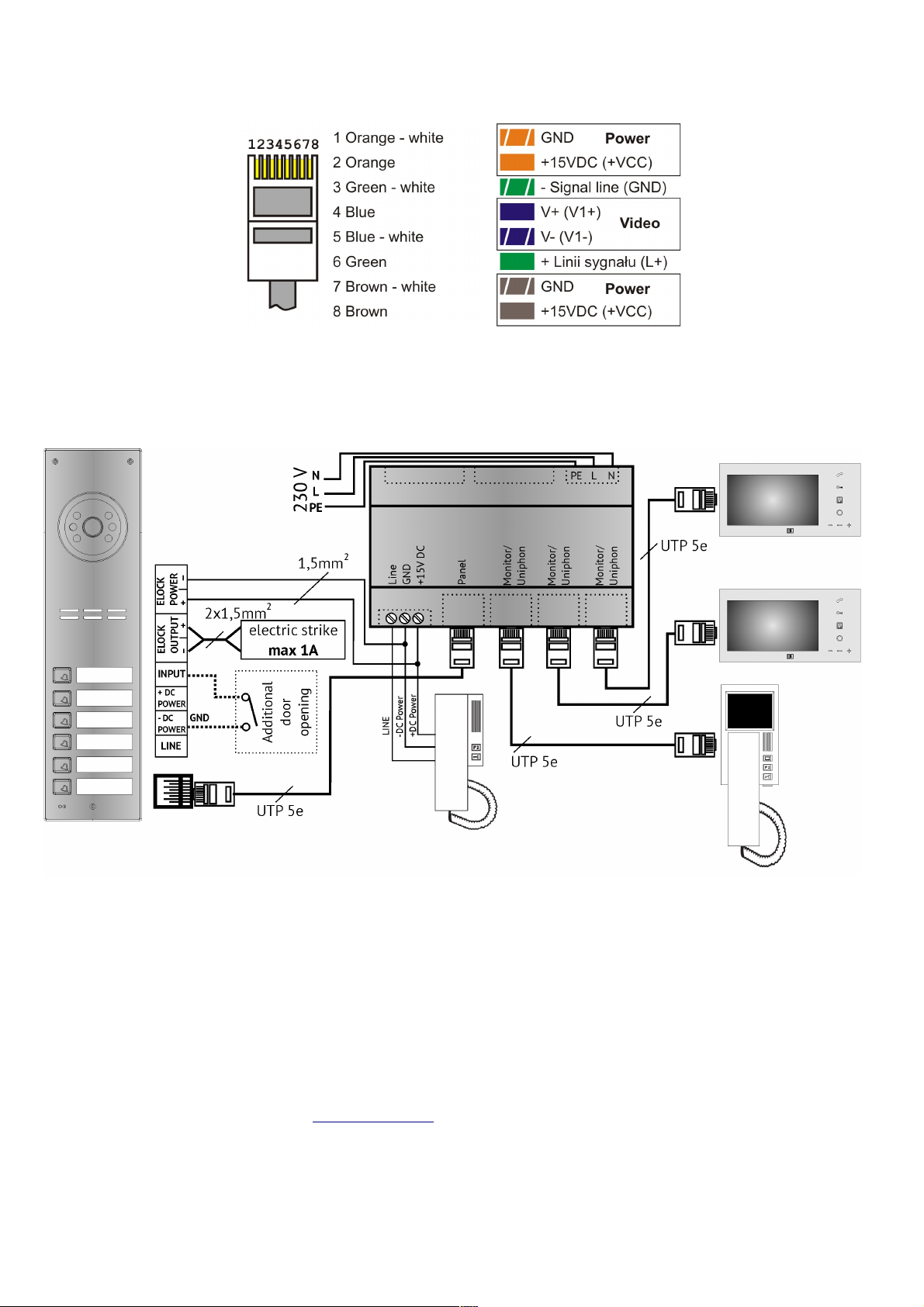
RJ45 plug should be tightened as per T568B standard, and signals in each line are shown in Fig. 3.
Before switching on the power supp y, make sure that a connections have been made according to the diagram,
the RJ45 p ugs are proper y c amped and there are no short circuits between the wires.
Fig. 3. Lines set-up in J45 plug
Fig. 4 shows the basic COMO/Familio PRO system connection diagram.
Fig. 4 Basic COMO/Familio P O system connection diagram
More COMO/Fami io PRO system features (support for more inside monitors, connection with
others, and description of typica issues) can be found in the Digital COMO PRO Panel
Operating Manual avai ab e at www.aco.com.p .
DISPOSAL OF WASTE ELECTRICAL EQUIPMENT
Do not dispose of waste electrical equipment with other (household / municipal) waste types. Dispose of it separately as
permitted by law. Consult the authority of jurisdiction or licensed waste recycling service providers. - Directive 2002/96/EC
of 2 /01/2003
IU0104enVC.1914
Table of contents
Popular Power Supply manuals by other brands


Teledyne
Teledyne Power Pod 400 instruction manual

Selectronic
Selectronic SP PRO Custom Installation Notes

Samson
Samson 5024-1 Series Mounting and operating instructions

Allen-Bradley
Allen-Bradley 1769-PA2 installation instructions

ULTIMATRON FRANCE
ULTIMATRON FRANCE ULT-1500BXS manual

Elmdene
Elmdene G240 BM Series instruction sheet