manuals.online logo
Brands
  1. Home
  2. •
  3. Brands
  4. •
  5. Elmdene
  6. •
  7. Power Supply
  8. •
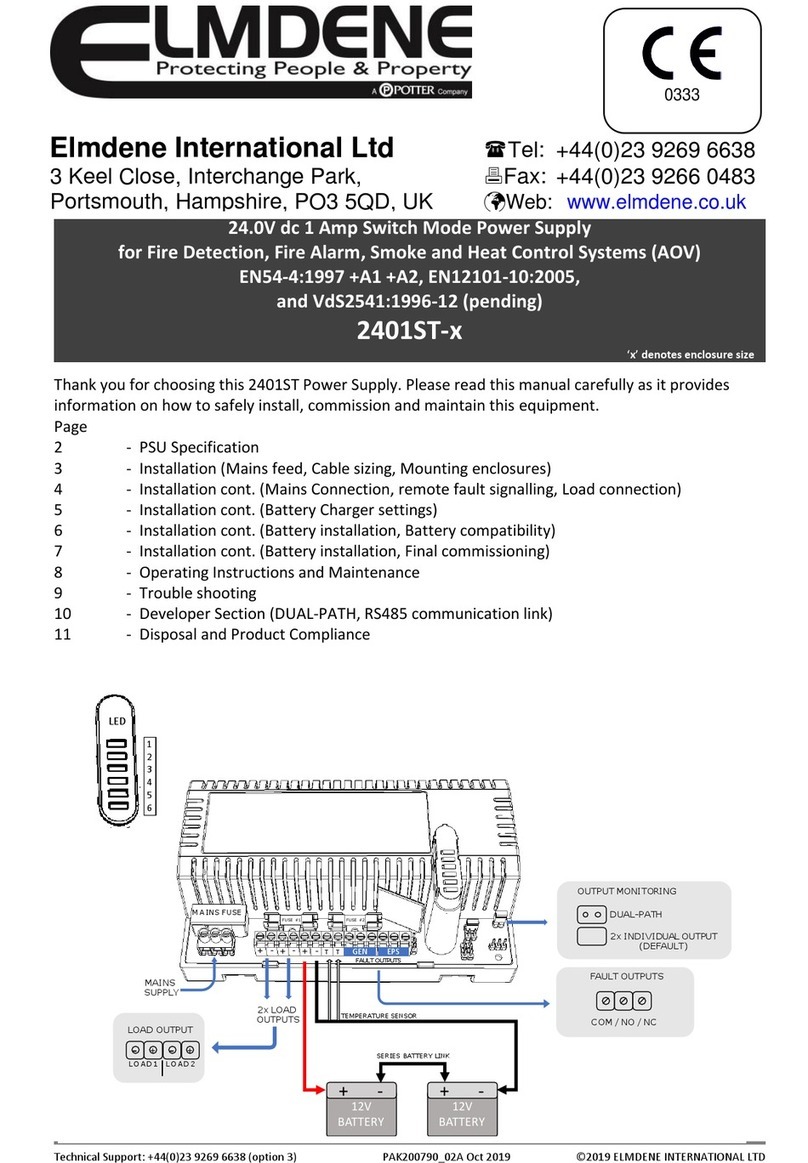
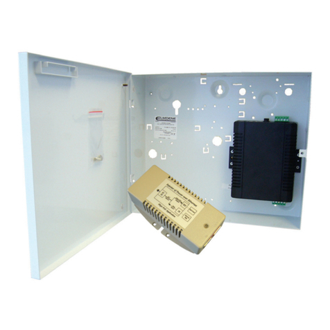
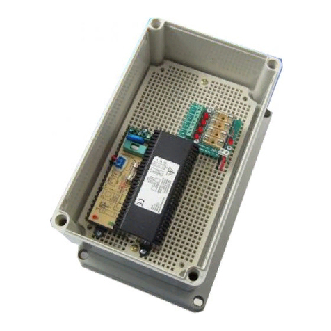
  9. Elmdene G240 BM Series User manual

Elmdene G240 BM Series User manual

1
Technical Support Line +44 (0)2392 696638 G240xBM-x-y PAK200536_01G May 2016 Elmdene International Ltd ©
27.6V
DC
S
WITCH
M
ODE
P
OWER
S
UPPLIES
W
ITH
R
EMOTE
F
AULT
S
IGNALLING AND
B
ATTERY
M
ONITORING
Models:
G240xBM y
Where ‘x’ is max load current and ‘y’ is Enclosure type
F
EATURES
High efficiency cost effecti e power supply ideal for use in Fire, Access Control and General Security applications.
Featuring a regulated 27.6Vdc output supplying continuous full rated current to load plus additional current for
charging 2 x 12V standby batteries. Maximum battery life is assured using deep discharge protection to pre ent
premature battery failure when operating in standby mode for extended periods. Two sets of olt-free contacts are
pro ided to signal (i) loss of mains and (ii) battery and loss of output faults. The uni ersal mains input oltage enables
the power supply to be used across a wide geographical area. The highly efficient switch mode design ensures low
operating costs, generates less heat and with a small physical size increases the room a ailable for additional PCBs or
cables. The modular construction simplifies maintenance.
•Continuous full rated current to load •Re erse battery connection protection
•Additional current to charge 2 x 12V standby
batteries
•Modular construction for ease of maintenance and
installation
•Battery Deep Discharge Protection
•G2403 & G2405 - Full electronic short circuit and
o erload protection on load output (under mains power
only)
•Uni ersal mains input oltage 90-264Vac •G2401 & G2402 - Fuse protection
•Volt free contact signalling mains failure •Mains transient protection circuit
•Volt free contact signalling output and battery faults •Green Mains present LED
•High efficiency electronics for reduced running costs
and lower operating temperatures
•Yellow Fault LED
•Installer safe design with all high oltage electronics
fully shrouded
•Orange Battery Charging LED ( isible on PCB only)
S
PECIFICATION
Input Specification
Voltage (rated) / (operating) 100-240Vac / 90-264Vac (Both at 50 – 60Hz)
Max Current / Input Fuse See Model Specification Table
Max standby Power 0.8W (No load and no battery connected)
Output Specification
Voltage 27.0 – 28.0Vdc (27.6Vdc nominal) on mains power
21.0 – 24.7Vdc on battery standby
Max load current / load fuse See Model Specification Table
Ripple 100 mV pk-pk max
O erload Electronic shutdown until o erload or short circuit remo ed
(under mains power only) (G2403BM & G2405BM)
Fuse Protection (G2401BM & G2402BM)
Elmdene International Ltd
Tel: +44 (0)23 9269 6638
3 Keel Close, Interchange Park, Fax: +44 (0)23 9266 0483

Portsmouth,
Hampshire
,
PO3 5QD
, UK

Web:
www.elmdene.co.uk
2
Technical Support Line +44 (0)2392 696638 G240xBM-x-y PAK200536_01G May 2016 Elmdene International Ltd ©
Standby Battery
Battery Type 2 x 12V Val e Regulated Lead Acid
Battery Capacity See below under enclosure size.
Battery Charging Fuse protection See Model Specification Table
Battery Re-Charge Time <24hrs (to 80% of 8Ah capacity)
Mechanical
Model Enclosure Dimensions
w x h x d [external] (mm)
Max Battery
Capacity
Weight (kg)
[excluding battery]
G240xBM C 330 x 275 x 80 2 x NP7 (7Ah)
G2401BM 3.16
G2402BM 3.22
G2403BM, G2405BM 3.30
G240xBM R 390 x 410 x 80 2 x NP17 (17Ah)
G2401BM 6.03
G2402BM 6.09
G2403BM, G2405BM 6.17
G240xBM H 420 x 420 x 180 2 x NP38 (38Ah) G2403BM, G2405BM 8.53
Environmental
Temperature -10 to +40°C (operating) 75% RH non-condensing
-20 to +80°C (storage)
S
IGNALLING
O
UTPUTS
GEN Fault (general) 0.1 A @ 60 VDC N/O olt-free contact.
Open when battery disconnected, output fuse fail, battery fuse fail,
output short circuit or low output oltage.
EPS Fault (mains) 0.1 A @ 60 VDC N/O olt-free contact.
Open when loss of mains for more than 8s.
C
ONNECTIONS
O/P +, - Connection to equipment to be powered (Obser e polarity)
BATT +, - Connection to standby battery. Use cables pro ided (Obser e polarity)
GEN Fault Volt-free contacts for general faults
EPS Fault Volt-free contacts for loss of mains indication
I
NSTALLATION
I
NSTRUCTIONS
This unit is only suitable for installation as permanently connected equipment. This PSU is NOT SUITABLE for external
installation. This unit must be fed from a mains power source ha ing a separate (appro ed) disconnect de ice and fitted
with a fuse or other o er-current protection de ice rated at 3A maximum. Ensure that the disconnect de ice used has
appropriate earth fault protection to the applicable standard. EQUIPMENT MUST BE EARTHED. Before installation,
ensure that external disconnect de ice is OFF.The PSU should be installed according to all rele ant safety regulations
applicable to the application.
Mounting
1) Mount securely in correct orientation allowing minimum clearance – see diagram.
2) Route mains and low oltage output cables ia different knockouts and/or cable entry holes.
3) Use bushes and cable glands rated to UL94 HB minimum.
Mains Power Up
4) Attach correctly rated mains cable (minimum 0.5mm
2
[3A], 300/500Vac). Fasten with cable ties.
5) Apply mains power. Check for 27.6Vdc on load outputs. Check Green Mains LED is ON.
6) Disconnect mains power.
3
Technical Support Line +44 (0)2392 696638 G240xBM-x-y PAK200536_01G May 2016 Elmdene International Ltd ©
Load Output
7) Attach correctly rated load cable and fasten using cable ties. Note polarity.
8) Apply mains power. Check Green Mains LED is ON.
9) NOTE: Yellow Fault LED may flash to indicate no battery has been connected. This is normal.
10) Verify load is operating correctly.
11) Disconnect mains power.
G2401BM, G2402BM G2403BM, G2405BM
Signalling Outputs
12) Connect EPS and GEN fault outputs to appropriate inputs of control equipment.
Standby Battery
13) Attach supplied battery cables to terminal block and batteries. NOTE: ensure correct polarity!
Red lead to + e of battery 1, Black lead to - e of battery 2.
Connect - e of battery 1 to + e of battery 2 using short link lead
14) Apply mains power. Check Green Mains LED is ON and Orange Charging LED is ON
15) Check there is no fault indication on Yellow Fault LED.
16) Disconnect mains power. Check that the batteries continue to supply oltage and current to the load. Check
Green Mains LED is OFF and the control panel displays a Loss of Mains (EPS) fault.
NOTE: Batteries must ha e sufficient charge to supply the load
17) Reconnect mains power. Check Green Mains LED is ON.
18) Remo e Load fuse and check Yellow Fault LED is ON and control panel shows a General PSU fault.
19) Replace Load fuse. Check Yellow Fault LED is OFF and General PSU fault has cleared at the control panel
M
ODEL
S
PECIFICATION
T
ABLE
G2401BM G2402BM G2403BM G2405BM
Output Current 1A 2A 3A 5A
Max Mains Input Current (at 90Vac) 1.0A 1.3A 1.4A 2.0A
Mains Input Fuse (20mm HRC) T2.0A T2.0A T3.15A T3.15A
Output Fuse (20mm) F1.0A F2.0A F3.15A F5.0A
Battery Fuse (20mm) F1.0A F2.0A F3.15A F5.0A
O
PERATING
I
NSTRUCTIONS
This unit is intended for use by Ser ice Personnel only - There are NO USER SERVICEABLE parts inside.
The Green Mains LED will be illuminated whilst the mains supply is present. In the e ent of a fault condition, the Yellow
Fault LED will be illuminated.
The Orange Battery Charging LED will be illuminated when the battery is not fully charged and is charging normally.
When the battery is fully charged, this LED will be extinguished.
10cm all round
.
N
L
E
10cm all round
.
L E N
4
Technical Support Line +44 (0)2392 696638 G240xBM-x-y PAK200536_01G May 2016 Elmdene International Ltd ©
M
AINTENANCE
There is no regular maintenance required of the PSU other than periodic testing and replacement of the standby
batteries. Reference should be made to the battery manufacturer’s documentation to determine typical/expected
battery life with a view to periodic replacement of the battery.
If the output of the PSU fails the cause of the failure should be in estigated e.g. short circuit load. The fault should be
rectified before restoring power to the PSU. The fuses may need to be replaced. Ensure the correct fuse rating and
type is used.
L
OCAL
I
NDICATORS
M
AINS
LED
(
GREEN
)
F
AULT
LED
(
YELLOW
) C
HARGE
LED
(
ORANGE
) S
TATUS
ON OFF OFF NORMAL - battery fully charged
ON OFF ON NORMAL - battery charging
ON 1s ON, 1s OFF ON or OFF FAULT - see Signalling Outputs
OFF 0.1s ON, 3s OFF OFF
FAULT - Mains Loss
PSU operating on battery
standby
OFF OFF OFF FAULT - No Output
Mains and Battery loss
C
OMPLIANCE
This power supply unit meets the essential requirements of the following European Directi es:
Low Voltage: 2014/35/EU EMC: 2014/30/EU
WEEE: 2012/19/EU RoHS2: 2011/65/EU
D
ISPOSAL OF
P
RODUCT AT
E
ND OF
L
IFE
This product falls within the scope of EU Directi es 2012/19/EU Waste Electrical and Electronic Equipment (WEEE) and
2013/56/EU (Battery). At the end of life, the product must be separated from the domestic waste stream and disposed
ia an appropriate appro ed WEEE disposal route in accordance with all national and local regulations.
Before disposal of the product, any batteries must be remo ed, and disposed separately ia an appropriate appro ed
battery disposal route in accordance with all national and local regulations. Package used batteries safely for onward
transport to your supplier, collection point or disposal facility.
Caution: Ris of fire or explosion if bare battery wires are allowed to touch.
See Specification for battery type information. The battery is marked with the crossed out wheelie bin symbol, which
may include lettering to indicate cadmium (Cd), lead (Pb), or mercury (Hg).
For more information see: www.re y lethis.info
The pa kaging supplied with this produ t may be re y led.
Please dispose of pa kaging a ordingly.

This manual suits for next models

9

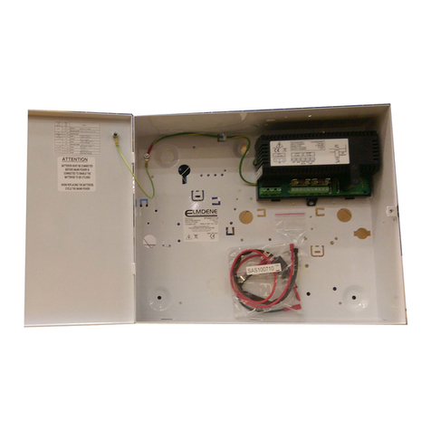
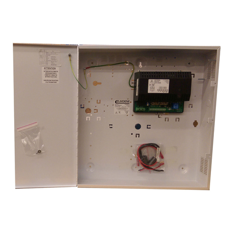
Other Elmdene Power Supply manuals

Elmdene G1380xBM Series User manual

Elmdene

Elmdene G1380xBM Series User manual

Elmdene LPS-12-G2 Instruction Manual

Elmdene

Elmdene LPS-12-G2 Instruction Manual

Elmdene 2401ST User manual

Elmdene

Elmdene 2401ST User manual

Elmdene 2405ST Series User manual

Elmdene

Elmdene 2405ST Series User manual

Elmdene 2405ST Series User manual

Elmdene

Elmdene 2405ST Series User manual

Elmdene G1380 BMU-y Series User manual

Elmdene

Elmdene G1380 BMU-y Series User manual

Elmdene G2410BMU User manual

Elmdene

Elmdene G2410BMU User manual

Elmdene STX2405-E User manual

Elmdene

Elmdene STX2405-E User manual

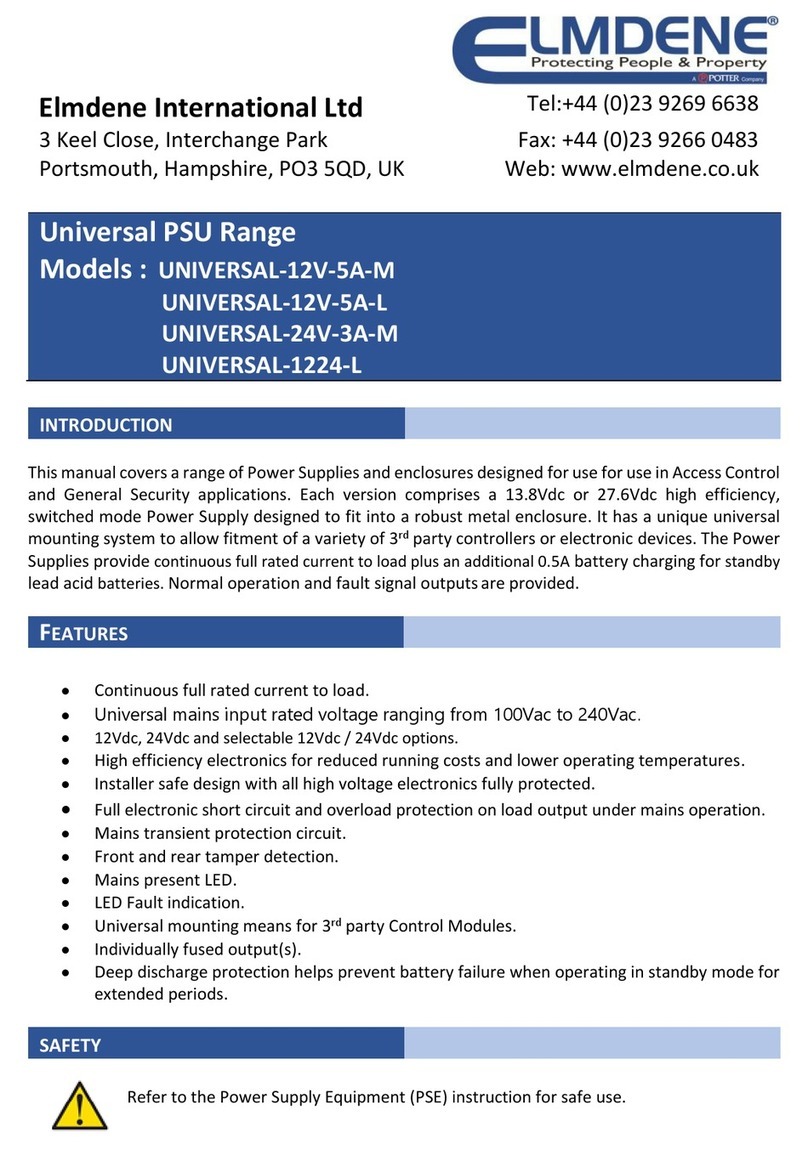
Elmdene UNIVERSAL-12V-5A-M User manual

Elmdene

Elmdene UNIVERSAL-12V-5A-M User manual

Elmdene G13804NU User manual

Elmdene

Elmdene G13804NU User manual

Elmdene STX2401-MOD User manual

Elmdene

Elmdene STX2401-MOD User manual

Elmdene STX2405-MOD User manual

Elmdene

Elmdene STX2405-MOD User manual

Elmdene 2401ST User manual

Elmdene

Elmdene 2401ST User manual

Elmdene STX2410-H User manual

Elmdene

Elmdene STX2410-H User manual

Elmdene 20182423N User manual

Elmdene

Elmdene 20182423N User manual

Elmdene G1380xN-y-s Series User manual

Elmdene

Elmdene G1380xN-y-s Series User manual

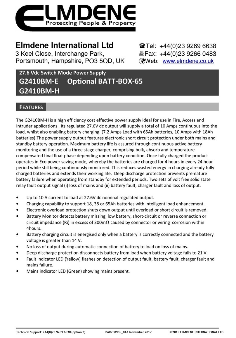
Elmdene G2410BM-E User manual

Elmdene

Elmdene G2410BM-E User manual

Elmdene STX2402-MOD User manual

Elmdene

Elmdene STX2402-MOD User manual

Elmdene STX2401-C User manual

Elmdene

Elmdene STX2401-C User manual

Elmdene STX2402 Series User manual

Elmdene

Elmdene STX2402 Series User manual

Elmdene GEN2-08 Series User manual

Elmdene

Elmdene GEN2-08 Series User manual

Elmdene STX2410-MOD User manual

Elmdene

Elmdene STX2410-MOD User manual

Elmdene LPS-ENC-T Instruction Manual

Elmdene

Elmdene LPS-ENC-T Instruction Manual

Elmdene GEN3-08-y User manual

Elmdene

Elmdene GEN3-08-y User manual

Popular Power Supply manuals by other brands

ADEMCO PS 24 installation instructions

ADEMCO

ADEMCO PS 24 installation instructions

SFC Energy EFOY Pro Series Hints & Tips

SFC Energy

SFC Energy EFOY Pro Series Hints & Tips

Puls PIANO PIM60.241 manual

Puls

Puls PIANO PIM60.241 manual

Powerwerx PWRbox2 user manual

Powerwerx

Powerwerx PWRbox2 user manual

Kohler MT80CHP Installation

Kohler

Kohler MT80CHP Installation

Schlage PS906 installation instructions

Schlage

Schlage PS906 installation instructions

Olympus TH4 instructions

Olympus

Olympus TH4 instructions

Meech Hyperion 906 operating manual

Meech

Meech Hyperion 906 operating manual

Elsner KNX PS640-IP 2U installation instructions

Elsner

Elsner KNX PS640-IP 2U installation instructions

Eikon ES Series user guide

Eikon

Eikon ES Series user guide

TDK-Lambda CUS600M instruction manual

TDK-Lambda

TDK-Lambda CUS600M instruction manual

Delta Elektronika SM15K Series product manual

Delta Elektronika

Delta Elektronika SM15K Series product manual

BGS technic 3383 Safety and operating instructions

BGS technic

BGS technic 3383 Safety and operating instructions

SECO-LARM Enforcer Video EVP-1SA4P4UL Specifications

SECO-LARM

SECO-LARM Enforcer Video EVP-1SA4P4UL Specifications

Thermal Dynamics CE CutMaster 50 instruction manual

Thermal Dynamics

Thermal Dynamics CE CutMaster 50 instruction manual

M-system R3Y-SS16N instruction manual

M-system

M-system R3Y-SS16N instruction manual

ESYLUX CU PS DALI manual

ESYLUX

ESYLUX CU PS DALI manual

SSD NEB/3U product manual

SSD

SSD NEB/3U product manual

manuals.online logo
manuals.online logoBrands
  • About & Mission
  • Contact us
  • Privacy Policy
  • Terms and Conditions

Copyright 2025 Manuals.Online. All Rights Reserved.