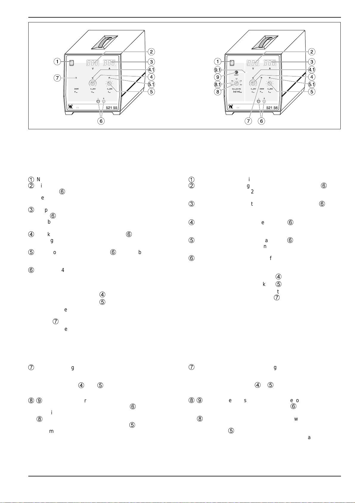
LEYBOLD 521 55 User manual

Physik Chemie ⋅Biologie Technik LEYBOLD DIDACTIC GMBH
3/97-Lu/Pr/Sf- Gebrauchsanweisung 521 55
Instruction Sheet 521 56
These devices are extra-low voltage sources with electronic
power limiting for supplying high direct currents (e.g. for
supplying electromagnets for high field strengths). They supply
a regulated, continuously adjustable DC voltage with low resi-
dual ripple which is stabilized with respect to current (0 to 20 A)
and voltage (0 to 24 V). Theycan be used as a constant-current
or constant-voltage source. Two digital LED displays enable si-
multaneous current and voltage monitoring.
The triangular wave-form power supply (521 56) additionally al-
lows you to control the curve of the current
I
(
t
) over time so that
it rises and falls with a constant slope |d
I
/d
t
| between 0.2 A and
the set maximum current value; the value for |d
I
/d
t
| can be set
continuously between 0.2 A/s and 2.2 A/s. In this mode, you
can e.g. generate slowly alternating magnetic fields in air coils
for experiments to derive the law of induction (see Fig. 2).
1 Safety notes
Die Geräte sind Kleinspannungsquellen zur Entnahme hoher
Gleichströme (z. B. zur Versorgung von Elektromagneten für
große Feldstärken) mit einer elektronischen Leistungsbegren-
zung. Sie liefern in Strom (0 bis 20 A) und Spannung (0 bis
24 V) stabilisierte, geregelte und stufenlos einstellbare Gleich-
spannung geringer Restwelligkeit. Sie können als Konstant-
strom- oder als Konstantspannungsquelle eingesetzt werden.
Zwei LED-Digitalanzeigen zeigen Strom und Spannung gleich-
zeitig an.
Das Dreieckstromnetzgerät (521 56) ermöglicht es außerdem,
den zeitlichen Verlauf des Stromes
I
(
t
) so zu steuern, daß er mit
konstanter Steigung |d
I
/d
t
| von 0,2 A bis zum gewählten Maxi-
malwert für den Strom ansteigt und abfällt; der Wert für |d
I
/d
t
|
kann stufenlos von 0,2 A/s bis 2,2 A/s eingestellt werden. In
dieser Betriebsart können z.B. in Luftspulen langsame magne-
tische Wechselfelder erzeugt werden für Versuche zur Herlei-
tung des Induktionsgesetzes (siehe Fig. 2).
1 Sicherheitshinweise
Hochstromnetzgerät,
Dreieckstromnetzgerät
High Current Power Supply
Triangular Wave-Form Power Supply
•Belüftungsschlitze nicht abdecken (Wärmestau).
•Bei Unterbrechung des Sekundärstromkreises durch die
elektronische Temperaturüberwachung (z.B.bei Wär-
mestau durch Abdecken der Belüftungsschlitze – ange-
zeigt durch Aufleuchten der LEDs (4.1), (5.1) und
7
sowie
durch Null-Anzeige in beiden Displays – Gerät abschalten,
abkühlen lassen und wieder in Betrieb nehmen. Falls die 3
LED noch immer leuchten, Gerät erneut abschalten und
weiter abkühlen lassen.
•Nur solche Verbraucher und Experimentierkabel verwen-
den, deren Belastbarkeit für den gewählten Strom ausreicht.
Für Hochstromversuche empfehlenswerte Kabel: Sicher-
heits-Experimentierkabel (500 600 ff.)
•Bei der Entnahme hoher Ströme kann es zu starker Erwär-
mung der Verbraucher kommen; bei Kurzschluß können an
den Verbrauchern Funken entstehen.
•Falls der auf dem Leistungsschild(Gehäuse-Rückseite) auf-
gedruckte Wert für die Netzanschlußspannung von dem
ortsüblichen Wert abweicht, Gerät zum Umrüsten in trans-
portgerechter Umverpackung an Leybold Didactic schicken.
•Do not cover the ventilation slits (danger of overheating).
•In the event that the temperature monitor interrupts the se-
condary circuit (e.g. in the event of overheating due to
blockage of the ventilation slits) – indicated when LEDs
(4.1), (5.1) and
7
light up, as well as by the two displays
dropping to zero – switch off the device and allow it to cool
before switching it back on. If the three LEDs still light up,
switch off the device again and allow it to cool further.
•Use only loads and connecting leads which have a load ca-
pacity sufficient for the selected current level.
Recommended leads for experiments with high current:
Safety connection leads (500 600 ff).
•When working with high current levels, the loads can become
very hot; short circuits can cause sparking at the loads.
•If the mains voltage value given on the rating plate (rear of
device) is different from your local mains voltage, pack the
device in appropriate transport packaging and return it to
Leybold Didactic for conversion.

2 Beschreibung, technische Daten, Lieferumfang
(siehe Fig. 1.1/1.2)
1
Netzschalter mit Betriebanzeigeleuchte
2
Display mit 3-stelliger Digitalanzeige für die Spannung an
Ausgang
6
;
Meßbereich: 0 bis 24 V
Genauigkeit des Spannungsmessers: ±1 % vom Endwert
3
Display mit 3-stelliger Digitalanzeige für den Strom an Aus-
gang
6
;
Meßbereich; 0 bis 20 A
Genauigkeit des Strommessers: ±2 % vom Endwert
4
Stellknopf für Spannung an Ausgang
6
;
Anzeige des Konstantspannungsbetriebs mit LED (4.1)
(siehe Abschnitt 3.1);
5
Stellknopf für den an Ausgang
6
entnehmbaren Strom;
Anzeige des Konstantstrombetriebs mit LED (5.1) (siehe
Abschnitt 3.2)
6
Ausgang (4-mm-Sicherheitsbuchsenpaar) für Spannung
und Strom,
elektronisch geregelt, stabilisiert, geglättet;
stufenlos einstellbar von
- 0 bis 24 V mit Stellknopf
4
und
- 0 bis 20 A mit Stellknopf
5
- mit einer elektronischen Leistungsbegrenzung bei einer
Ausgangsleistung von mehr als 240 W (angezeigt von
LED
7
)
Restwelligkeit bei Vollast: < 50 mVss
Stabilisierung bei Vollast: < 1 % vom Endwert
bei ±10 % Netzspannungs-
schwankung: < 0.2 % vom Endwert
Restspannung in Nullstellung: < 0.2 % vom Endwert
Ausgang erdfrei, kuzschlußfest und fremdspannungssicher
7
LED zur Anzeige der Leistungsbegrenzung
bei aktiver Leistungsbegrenzung (bei Ausgangsleistungen
über 240 W) keine Erhöhung von Spannung oder Strom an
den Stellknöpfen
4
oder
5
möglich (siehe Abschnitt 3.3)
8
,
9
Funktionsteile zur “Dreieck-Steuerung” für den zeitlichen
Verlauf des Stromes
I
(
t
) an Ausgang
6
( nur vorhanden
beim Dreieckstromnetzgerät, 521 56, siehe Fig. 1.2)
8
Stellknopf zur Wahl der Steigung |d
I
/d
t
|, mit dem der
Strom zwischen 0,2 A und dem mit
5
eingestellten Ma-
ximalwert ansteigt und abfällt;
- stufenlos einstellbar von 0,2 A/s bis 2,2 A/s
- Linearitätdabweichung: < 3 % vom Endwert
2 Description, technical data, scope of supply
(see Fig. 1.1/1.2)
1
Mains switch with on-indicator lamp
2
Display unit with 3-digit display for voltage at output
6
;
measuring range: 0 to 24 V
accuracy of voltage meter: ±1 % of upper range value
3
Display unit with 3-digit display for current at output
6
;
measuring range: 0 to 20 A
accuracy of ammeter: ±2 % of upper range value
4
Adjustment knob for voltage at output
6
;
constant-voltage operation indicated by LED (4.1) (see
section 3.1)
5
Adjustment knob for current at output
6
;
constant-current operation indicated by LED (5.1) (see
section 3.2)
6
Output (pair of 4-mm sockets) for voltage and current,
electronically regulated, stabilized, smoothed;
continuously adjustable from
- 0 to 24 V with adjustment knob
4
and
- 0 to 20 V with adjustment knob
5
- with electronic power limiter at an output power greater
than 240 W (indicated by LED
7
)
Residual ripple at full load < 50 mVpp
Stabilization at full load: < 1 % of upper range value
at 10 % mains voltage
fluctuation < 0.2 % of upper range
value
Residual voltage in zero
position < 0.2 % of upper range
value
Output floating, short-circuit proof and proof against interfe-
rence voltage
7
LED for indicating current limiting
when active power limiting is in operation (at output power
levels above 240 W), it is not possible to increase the volt-
age or current at knobs
4
or
5
(see section 3.3).
8
,
9
Control elements for triangular-wave form signal of the
curve of the current
I
(
t
) over time at
6
(triangular wave-
form power supply 521 56 only, see Fig. 1.2).
8
Knob for selecting the slope |d
I
/d
t
| at which the current
is to rise and fall between 0.2 A and the maximum value
set using
5
- continuously adjustable between 0.2 A/s and 2.2 A/s
- Linear deviation: < 3 % of upper range value
Fig. 1.1Hochstromnetzgerät (521 55) Fig. 1.2 Dreieckstromnetzgerät (521 56)
High current power supply (521 55) Triangular wave-form power supply (521 56)
2

9
Pushbutton for activating/deactivating triangular wave-
form mode;
operational readiness indicated by LED (9.1);
set value displayed on scale (8.1)
- 0.2 A/s scale division
- Reading accuracy: 10 % of set value
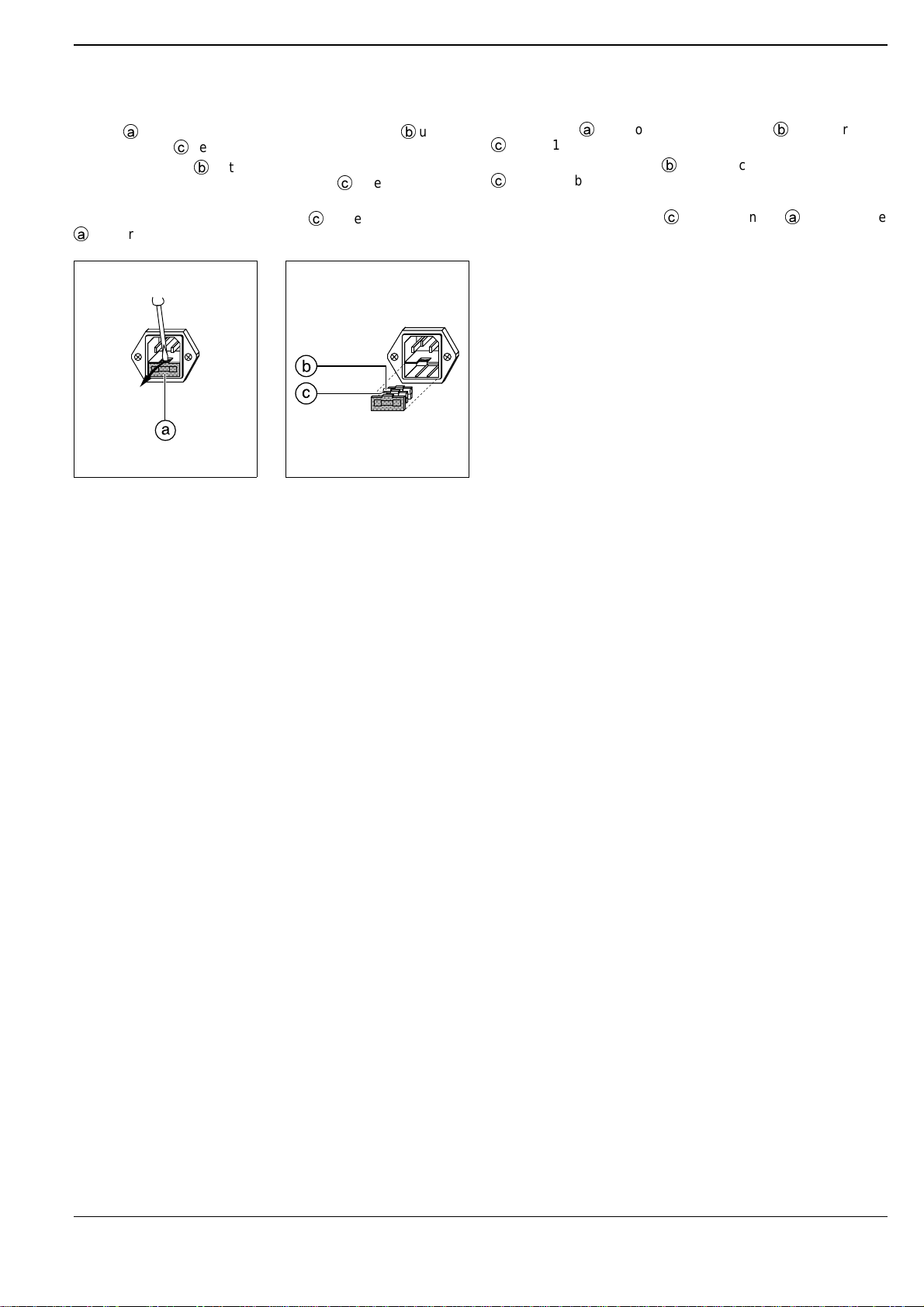
Appliance-plug connector with integrated holder for primary
and spare fuse on rear of device.
Mains connection cable included in scope of supply.
Two folding feet in bottom of housing for inclining the device.
Additional technical data
Protection:
- Primary side: Fuse
see fuse rating plate above on rear of de-
vice.
- Secondary side: electronic temperature monitoring auto-
matically cuts out current in the event of
thermal overload which can damage the
electronic components of the device.
Interruption of current indicated when indi-
cated when LEDs (4.1), (5.1) and
7
light
up, as well as by the two displays drop-
ping to zero
Mains voltage 230 V AC; 50/60 Hz or 115 V AC
(according to rating plate on rear
of device)
Power consumption: 450 VA
Dimensions: 20 cm x 21 cm x 23 cm
Weight: 3.0 kg
3Operation
3.1 Using the device as a constant-voltage source
Set the current-limiting knob
5
to the maximum position (full
right deflection). LED (4.1) lights up, indicating that the device is
operating in constant-voltage mode. Set the desired voltage
value using knob
4
(the value appears in display
2
).
Option:
If you also want to limit the maximum current consumption to
values below 20 A in order to protect the connected apparatus,
disconnect the power supply from the circuit, short output
6
(e.g. using a bridging plug) and turn the current-limiting knob
5
down until the desired maximum current is flowing (indicated by
display 3
and LED (5.1)). Then reduce the voltage to zero with
knob
4
, remove the short-circuit and reconnect output
6
to the
circuit.
Now, when you increase the voltage with knob
2
, no current
greater than the set limit value can flow regardless of the con-
nected load. When current limiting is activated, LED (5.1) lights
up, and it is not possible to increase the voltage further with
knob
4
.
3.2 Using the device as a constant-current source
Set the voltage-limiting knob
4
to the maximum position (full
right deflection). LED (5.1) lights up, indicating that the device is
operating in constant-current mode. Set the desired current va-
lue using knob
5
; the value appears in display
3
.
Option:
If you also want to limit the maximum voltage to values below
24 V in order to protect the connected apparatus, make sure
output
6
is open and turn the voltage-limiting knob
4
down
until the desired maximum voltage is present (display
2
and
LED (4.1)). Then reduce the current to zero with knob
4
and
connect output
6
to the circuit.
9
Taster zum Ein- bzw. Ausschalten der Dreieckstrom-
Modus;
Anzeige der Funktionsbereitschaft durch LED (9.1)
Anzeige des eingestellten Wertes auf Skala 8.1
- 0,2-A/s-Teilung
- Ablesegenauigkeit: ±10 % vom eingestellten Wert
Auf der Gehäuse-Rückseite Steckerwanne mit integriertem Si-
cherungshalter für Primär- und Reservesicherung.
Netzanschlußkabel im Lieferumfang enthalten.
Im Gehäuse-Boden 2 ausklappbare Füße zum Neigen des Ge-
rätes.
Weitere technische Daten
Sicherungen:
- Primärseite: Schmelzsicherung
Wert siehe Sicherungsschild auf der Ge-
häuse-Rückseite
- Sekundärseite: elektronische Temperaturüberwachung
zur automatischen Verhinderung der Stro-
mentnahme bei thermischer Überlastung,
durch die die Elektronik des Gerätes
Schaden nehmen kann;
Anzeige der Stromunterbrechung durch
Aufleuchten der LEDs (4.1), (5.1) und
7
sowie durch Null-Anzeige in beiden Dis-
plays
Netzanschlußspannung 230 V
"
; 50/60 Hz bzw. 115 V
"
(gemäß Leistungsschild auf der
Gehäuse-Rückseite)
Leistungsaufnahme: 450 VA
Abmessungen: 20 cm x 21 cm x 23 cm
Masse: 3,0 kg
3 Bedienung
3.1 Betrieb als Konstantspannungsquelle
Stellknopf
5
für die Strombegrenzung auf Maximum (Rechts-
anschlag)l stellen. Die LED (4.1) für Konstantspannungsbetrieb
leuchtet auf. Durch Betätigen des Stellknopfes
4
den ge-
wünschten Spannungswert einstellen (Anzeige in Display
2
).
Option
:
Soll zusätzlich der maximal entnehmbare Strom zum Schutz
der angeschlossenen Geräte auf Werte unter 20 A begrenzt
werden, so ist nun ohne angeschlossene Schaltung bei kurz-
geschlossenem Ausgang
6
(z.B. mittels Brückenstecker) der
Stellknopf
5
für die Strombegrenzung soweit zurückzudrehen,
bis der gewünschte Maximalstrom fließt (Anzeige im Display
3
sowie durch LED (5.1)). Sodann die Spannung mit Stellknopf
4
wieder auf Null zurückdrehen, den Kurzschluß entfernen und
Ausgang
6
mit der Schaltung verbinden.
Bei Erhöhen der Spannung mit Stellknopf
2
kann nun, unab-
hängig vom angeschlossenen Verbraucher, kein Strom ent-
nommen werden, der größer als der eingestellte Maximalwert
ist. Mit einsetzender Strombegrenzung leuchtet die LED (5.1)
auf, und eine weitere Erhöhung der Spannung mit dem Stell-
knopf
4
ist nicht möglich.
3.2 Betrieb als Konstantstromquelle
Stellknopf
4
für die Spannungsbegrenzung auf Maximum
(Rechtsanschlag) stellen. Die LED (5.1) für Konstantstrombe-
trieb leuchtet auf. Durch Betätigen des Stellknopfes
5
den ge-
wünschten Strom einstellen (Anzeige im Display
3
).
Option
:
Soll zusätzlich die maximal einstellbare Spannung zum Schutz
der angeschlossenen Geräte auf Werte unter 24 V begrenzt
werden, so ist bei offenem Ausgang
6
der Stellknopf
4
für die
Spannungsbegrenzung soweit zurückzudrehen, bis die ge-
wünschte Maximalspannung erreicht ist (Display
2
sowie LED
(4.1)). Sodann den Strom mit Stellknopf
4
wieder auf Null zu-
3

Now, when you increase the current with knob
5
, no voltage
greater than the set maximum value can flow regardless of the
connected load. When voltage limiting is activated, LED (4.1)
lights up, and it is not possible to increase the current further
with knob
5
.
3.3 Power limiting
LED
7
lights up when the power limiting function is activated,
which occurs when the output power exceeds 240 W. When
this occurs, it is no longer possible to increase the current and
voltage using knobs
4
and
5
.
Although the device can operate in power limiting mode without
sustaining any damage, stabilization is no longer ensured.The-
refore, you should work within the power limit and, where
necessary, reduce the current or voltage until LED
7
goes out.
3.4 Triangular mode (triangular wave-form power supply
521 56 only)
Pressing pushbutton
9
switches to triangular mode (indica-
ted by LED (9.1)). In this mode, the device supplies a current
I
(
t
) which varies over time. The current increases and decrea-
ses with a slope |d
I
/d
t
| at a rate which can be varied continuous-
ly between 0.2 A/s and 2.2 A/s in the range from 0.2 A to the
maximum value set using knob
5
, until pushbutton
9
is pres-
sed again and LED (9.1) goes out.
Triangular wave-form current is only presentwhen the device is
used as a constant current source without additional voltage
limiting (see section 3.2).
If voltage limiting is also set, the current only increases until
voltage limiting is activated; here, the slope |d
I
/d
t
| is zero. Once
the falling edge drops below the voltage-limiting threshold, the
current once more decreases with a constant slope of |d
I
/d
t
|.
This results in a trapezoidal curve form for the current
I
(
t
).
rückdrehen und den Ausgang
6
mit der Schaltung verbinden.
Bei Erhöhen des Stromes mit Stellknopf
5
kann nun, unabhän-
gig vom angeschlossenen Verbraucher, keine Spannung für
Ausgang
6
eingestellt werden, die größer ist als der eingestell-
te Maximalwert. Mit einsetzender Spannungsbegrenzung
leuchtet die LED (4.1) auf und eine weitere Erhöhung der Stro-
mes mit dem Stellknopf
5
ist nicht möglich.
3.3 Leistungsbegrenzung
Die LED
7
leuchtet, wenn sich das Gerät in der Leistungsbe-
grenzung befindet; das ist erst bei Ausgangsleistungen über
240 W der Fall. Spannung und Strom können dann an den
Stellknöpfen
4
und
5
nicht mehr erhöht werden.
DasGerät arbeitet zwar in der Leistungsbegrenzung, ohne
Schaden zu nehmen; die Stabilisierung ist aber nicht mehr ge-
währleistet. Es ist daher empfehlenswert, unterhalb der Lei-
stungsbegrenzung zu arbeiten und gegebenenfalls Strom oder
Spannung so weit zurückzunehmen, daß die LED
7
erlischt.
3.4 Dreieckstrom-Modus (nur beim Dreieckstromnetzge-
rät, 521 56)
Mit Taster
9
wird in den Dreieckstrom-Modus umgeschaltet
(angezeigt von LED (9.1)).Das Gerät liefert dann einen mit der
Zeit veränderlichen Strom
I
(
t
). Er nimmt mit einer von 0,2 A/s
bis 2,2 A/s stufenlos einstellbaren Steigung |d
I
/d
t
| zwischen
0,2 A und dem an Stellknopf
5
gewählten Maximalwert zu und
ab, bis der Taster
9
wieder betätigt wird und die LED (9.1) er-
lischt.
Dreieckstrom steht nur dann zur Verfügung, wenn man das Ge-
rät als Konstantstromquelle ohne zusätzliche Spannungsbe-
grenzung einsetzt (siehe Abschnitt 3.2).
Wird zusätzlich die Spannungsbegrenzung wirksam, so steigt
der Strom nur an bis zum Einsetzen der Spannungsbegren-
zung; hier ist die Steigung |d
I
/d
t
| Null. Wird in der abfallenden
Flanke die Spannungsbegrenzung wieder unterschritten, so
nimmt der Strom wieder mit konstantem |d
I
/d
t
| ab. Damit ergibt
sich ein trapezförmiger Verlauf des Stromes
I
(
t
).
Fig. 2
Versuchsanordnung zur Herleitung des Induktionsgesetzes (mit Induktionsspulen, aus 516 241, in Feldspule, 516 443 bzw. 444): Messung der
Induktionsspannung
U
als Funktion der Steigung |d
I
/d
t
| des Feldspulenstromes
I
Größenordnung der Induktionsspannung: 10-4 A
Experiment setup for deriving the law of induction (with induction coils from 516 241, in field coil 516 243 or 244): measuring the induction voltage
U
as a function of the slope |d
I
/d
t
| of the field-coil current
I
Order of magnitude of induction voltage: 10-4 A
4

LEYBOLD DIDACTIC GMBH ⋅Leyboldstrasse 1 ⋅D-50354 Hürth ⋅Phone (02233) 604-0 ⋅Telefax (02233) 604-222 ⋅ Telex 17 223 332 LHPCGN D
©byLeyboldDidactic GmbH, Printedin the FederalRepublicof Germany
Technical alterations reserved
4 Austausch der Primärsicherung
Wert siehe Sicherungsschild auf der Gehäuse-Rückseite.
Einsatz
a
mit Fassung für Primärschmelzsicherung
b
und Re-
servesicherung
c
heraushebeln (Fig. 3.1).
Defekte Sicherung
b
entfernen und durch die auf richtigen Si-
cherungswert überprüfte Reservesicherung
c
ersetzen (Fig. 3.2).
Neue Sicherung (Wert siehe Sicherungsschild auf der Gehäu-
se-Rückseite) als Reservesicherung
c
einsetzen und Einsatz
a
wieder einschieben.
4 Replacing the primary fuse
Refer to fuse rating plate on rear of device.
Pry out insert
a
with holder for primary fuse
b
and spare fuse
c
(Fig. 3.1).
Remove the defective fuse
b
and replace it with the spare fuse
c
which has been checked for the correct rating (Fig. 3.2).
Insert a new fuse (see fuse plate on rear of device for correct
rating) as the reserve fuse
c
and slide insert
a
back into the
device.
Fig. 3.2Fig. 3.1
This manual suits for next models
1
Other LEYBOLD Power Supply manuals