Heliocentris Energy Manager 2.0 User manual
Energy Manager 2.0
Instruction Manual

Energy Manager 2.0, Instruction Manual
Version 1
.0
March
2014
© Heliocentris
Industry GmbH
Rudower Chaussee 29
12489 Berlin
Germany
All rights reserved. No part of this
Instruction Manual may be reproduced, stored in a data
retrieval system or transmitted by any means without the prior written permission of the issuer.
The following exception applies: photocopying pages from the manual for instruction for or by
lecturers is allowed.
Components
of the Energy Manager 2.0 are protected by patents and / or utility patents.
Energy Manager 2.0
is a trademark of Heliocentris Industry GmbH, Germany.
We reserve the right to ma
ke changes.

Contents
1About This Document...................................................................... 7
1.1 Overview................................................................................................... 7
1.2 Notices and Symbols .................................................................................. 8
1.2.1 Symbols .................................................................................................... 8
1.2.2 Warnings .................................................................................................. 8
1.2.3 Tips .......................................................................................................... 8
1.3 Accompanying Documentation ....................................................................9
2Safety Instructions ........................................................................ 10
2.1 General Information on Safety & Responsibility ............................................10
2.2 Approved Use.......................................................................................... 11
2.3 Foreseeable Misuse .................................................................................. 11
2.4 Hazards during Approved Use ................................................................... 11
2.5 General Information on Operation............................................................. 12
2.5.1 Requirements for the Owner / Operator...................................................... 12
2.5.2 Requirements for the Location / Installation Location ....................................12
2.5.3 Requirements for the User ......................................................................... 13
3Components.................................................................................. 15
3.1 Energy Manager....................................................................................... 15
3.1.1 Front Side................................................................................................ 15
3.1.2 Back Side ................................................................................................ 18
3.2 Energy Manager Software Modules ............................................................ 19
3.3 Operating and Monitoring Software ........................................................... 21
3.4 Wireless Remote Access ............................................................................ 22
3.5 Extension Board (Option) .......................................................................... 23
4Getting Started............................................................................. 24
4.1 Scope of Delivery ..................................................................................... 24
4.2 Unpacking and Installation ........................................................................ 24
4.2.1 Unpacking and Visual Inspection................................................................ 24
4.2.2 Installation Tools ...................................................................................... 25
4.2.3 How to Mount the Energy Manager ............................................................ 25
4.3 How to Connect the Antenna..................................................................... 25
4.4 How to Insert SIM Card............................................................................. 26
4.5 How to Insert SD Card .............................................................................. 26
4.6 How to Connect Sensors and Actuators.......................................................26
4.6.1 How to Connect Cables and Plugs ............................................................. 27
4.6.2 Port Assignment ....................................................................................... 27
4.7 How to Ground the Energy Manager .......................................................... 29
4.8 How to Connect Power Supply ................................................................... 29
4.9 How to Use the Control Panel.................................................................... 31
4.9.1 Operating Areas of the Control Panel......................................................... 31
4.9.2 How to Select Menu Items ......................................................................... 32
Energy Manager 2.0 - Instruction Manual 3

Contents
4.9.3 How to Enter Digits................................................................................... 33
4.10 How to Log In as Service User.................................................................... 34
4.11 How to Configure the Modem ................................................................... 35
4.12 How to Configure Site-Specific Parameters .................................................. 36
4.12.1 How to Connect EM and RMS.................................................................... 36
4.12.2 How to Configure Battery Capacity............................................................. 37
4.12.3 How to Configure Fuel Sensors with Fuel Wizard..........................................37
5Operating..................................................................................... 39
5.1 LCD Menu Structure ................................................................................. 39
5.1.1 Main Menu.............................................................................................. 39
5.1.2 System Submenu ...................................................................................... 41
5.1.3 Genset Submenu...................................................................................... 44
5.1.4 Battery Submenu ...................................................................................... 48
5.1.5 Fuel Submenu.......................................................................................... 50
5.1.6 Load Submenu......................................................................................... 52
5.1.7 Aircon Submenu....................................................................................... 53
5.1.8 Free Cooling Unit (FCU) Submenu ............................................................. 54
5.1.9 Solar Submenu ........................................................................................ 56
5.1.10 Wind Submenu ........................................................................................ 57
5.1.11 Fuel Cell (Fcell) Submenu.......................................................................... 58
5.1.12 Rectifier Submenu..................................................................................... 60
5.1.13 Inverter Submenu ..................................................................................... 63
5.1.14 Site Submenu........................................................................................... 65
5.1.15 Shelter Submenu ...................................................................................... 66
5.1.16 Login Submenu........................................................................................ 67
5.1.17 Service Submenu...................................................................................... 67
5.1.18 Configuration Submenu ............................................................................ 69
5.2 How to Administer IP Settings..................................................................... 70
5.2.1 How to Display IP Address, Netmask and Gateway Address...........................70
5.2.2 How to Change IP address, Gateway or Netmask ........................................70
5.3 How to Update the EM Software ................................................................ 71
5.4 How to Reset Counters and Statistics Data................................................... 71
5.5 How to Observe Alarms and Other Events...................................................72
5.6 How to Copy Log Files to USB Flash Drive................................................... 74
6Decommissioning ......................................................................... 75
6.1 How to Decommission the Energy Manager ................................................75
6.1.1 How to Disconnect the Energy Manager...................................................... 75
6.2 How to Store the Energy Manager.............................................................. 76
6.3 How to Ship the Energy Manager ............................................................... 76
7Troubleshooting............................................................................ 77
7.1 FAQ ....................................................................................................... 77
8Maintenance and Service ............................................................. 79
8.1 Maintenance............................................................................................ 79
8.2 How to Shut Down and Restart Energy Manager ..........................................79
8.2.1 How to Reboot Energy Manager ................................................................ 79
4 Energy Manager 2.0 - Instruction Manual

Contents
8.2.2 How to Shut Down Energy Manager ........................................................... 80
8.2.3 How to Perform a Forced Restart................................................................ 80
8.2.4 How to Apply the Reset Button ................................................................... 80
8.3 How to Reset the GensetService Interval...................................................... 81
8.4 How to Remove the I/O Panel ................................................................... 82
8.5 How to Install the Extension Board (Option)................................................. 82
8.5.1 Unpacking and Visual Inspection................................................................ 82
8.5.2 Installation Tools ...................................................................................... 83
8.5.3 How to Connect Energy Manger and Extension Board ..................................83
8.5.4 How to Mount Energy Manger and Extension Board .....................................86
8.6 Cleaning ................................................................................................. 86
8.7 Service.................................................................................................... 86
8.8 Replacing Components............................................................................. 87
8.8.1 How to Replace Main Fuse........................................................................ 87
8.8.2 How to Replace SIM Card ......................................................................... 87
8.9 Disposal.................................................................................................. 88
9Disassembly and Removal............................................................ 89
10 Technical Data.............................................................................. 90
11 Appendix ...................................................................................... 95
11.1 Licenses .................................................................................................. 95
11.2 Abbreviations........................................................................................... 97
11.3 Glossary.................................................................................................. 98
11.4 Index ...................................................................................................... 99
Energy Manager 2.0 - Instruction Manual 5


1About This Document
If only the masculine or feminine form is used in parts of this manual, this
is only for readability and simplicity. Persons of the respective other
gender are always included.
1.1 Overview
This instruction manual is intended to help you understand, use and
maintain the product. It is organized as follows.
This chapter contains safety instructions and provides information on the
safe handling of the product. It is essential that you read and understand
this chapter.
This chapter presents the components of the product and their basic
functions.
This chapter describes the scope of delivery and the necessary steps for
initial startup of the product - from choosing a suitable installation
location to connecting all required components.
This chapter provides instructions for the operation of the product as far
as carried out at the device.
The necessary steps for the disassembly of the product and the conditions
for its packaging, storage and transport are described in this chapter.
This chapter describes possible problems and their solution.
This chapter describes all necessary measures arising in the product life
cycle, such as the maintenance, cleaning, service, warranty and disposal.
An overview of important technical data is provided at the end of the
instruction manual.
The abbreviations used in this manual are summarized in the appendix.
An index can be used for fast orientation.
Safety
Components
Getting Started
Operating
Maintenance and Service
Troubleshooting
Disassembly and Removal
Technical Data
Appendix
Energy Manager 2.0 - Instruction Manual 7

About This Document
1.2 Notices and Symbols
1.2.1 Symbols
The following symbols and labels are used in this manual:
Symbol or label Meaning
Instruction
Aids or prerequisites that are required prior to an action
1. Instructions in a specific sequence
Result of an action
, - List
Switch, key, button Refers to a switch, key, button or icon
Reference to page xReference to further information
Figure 1-1 Symbols in the instruction manual
1.2.2 Warnings
The following warnings are used:
DANGER
Warns of dangers causing fatal injury.
WARNING
Warns of dangers causing serious injury.
CAUTION
Warns of dangers causing injury.
NOTICE
Warns of physical damage to the product.
1.2.3 Tips
Useful tips are identified as follows:
TIP Provides further tips.
8 Energy Manager 2.0 - Instruction Manual

1.3 Accompanying Documentation
In addition to this instruction manual, the following documents are also
supplied with the Energy Manager:
•Live Access Application
−Instruction manual that describes the parameters and usage of
the graphical user interface and explains which parameters are
needed to administer special features.
−Online help explaining all parameters of the graphical user
interface (only available via LAA)
•Event Codes
Reference manual that describes all alarm, warning and
information events. For each event the responsible LAA settings
and possible solutions are provided.
Energy Manager 2.0 - Instruction Manual 9

Safety Instructions
2Safety Instructions
In this chapter you will find information on the safe handling of the
product. It is essential that you read and understand this chapter.
2.1 General Information on Safety & Responsibility
WARNING
Danger of injury due to improper use!
Improper use of the product can result in serious injuries.
Ensure that the manual is accessible at all times.
Make sure you have read and understood this
manual in its entirety.
Comply with all safety instructions and
warnings.
Store the manual and other documentation in a
safe place and pass them on to future owners of the product.
Comply with all local regulations.
Only use product components.
DANGER
Danger of death due to unauthorized modifications!
Conversions and modifications to the product can result in general
hazards (, danger of death due to electric shock).
Do not make modifications to the product or its individual
components.
Do not remove components (exception: See Replacing
Components on page 87).
It’s not allowed to replace parts and components which are
not described in this manual. Violation voids all warranty
claims.
DANGER
Danger of death due to handling electricity
For electrical wiring follow the country-specific safety
regulations for handling electricity.
For electrical installation comply with the local safety
regulations for handling electricity.
All devices must be connected separately with the earth circuit
connector and properly grounded.
10 Energy Manager 2.0 - Instruction Manual

Safety Instructions
2.2 Approved Use
The product has been designed for:
•Monitoring and controlling the power generation
•Reducing energy consumption and CO2emission
•Remote monitoring of site conditions such as temperature, current,
fuel consumption.
The product is not intended for any other purpose; any other use is not
approved.
2.3 Foreseeable Misuse
Do not use this product for:
•Operation beyond the technical specifications
•Operation beyond the approved operating environment
•Operation in potentially explosive areas
2.4 Hazards during Approved Use
The unit poses no special electrical hazards as long as the following
instructions are observed:
Use only the specified supply voltage, see Technical Data on page
90.
Do not short-circuit inputs and outputs.
Do not reverse the polarity of inputs and outputs.
Do not insert any mechanical parts, especially metal parts, into the
product through the ventilation slots.
Do not use liquids near the product.
Electricity
Energy Manager 2.0 - Instruction Manual 11

Safety Instructions
2.5 General Information on Operation
2.5.1 Requirements for the Owner / Operator
The owner / operator are responsible for the following:
Implementation of a risk analysis in accordance with national law
and regulations concerning occupational health and safety.
The owner / operator are responsible for compliance with local
safety regulations.
The owner / operator must ensure that the unit is accessible only
to the persons defined in this manual.
Unauthorized persons must be prevented, using corresponding
measures, from installing, operating or maintaining the system.
Installation, commissioning, shutdown and maintenance of the
system must be carried out by appropriately qualified personnel.
Only original or replacement parts and maintenance materials
approved by Heliocentris may be used. Violation voids the
warranty.
Heliocentris is not responsible for damage arising from the use of
unauthorized replacement parts and maintenance materials.
It is not allowed to replace parts and components which are not
described in this instruction manual. Violation voids all warranty
claims. the guarantee and all other requirements are lost.
The safety instructions and warnings listed in this instruction
manual must be observed.
2.5.2 Requirements for the Location / Installation Location
Before installation, the installation site is inspected by Heliocentris or an
authorized partner. The requirements for the location are included in the
inspection and are recorded, among other things, in the Site Survey.
The system must be operated in a telecommunication site that
complies with the local regulations.
The Energy Manager is designed for indoor installation in frost-
free premises with a maximum ambient temperature of 50°C in a
noncondensing environment.
The Energy Manager has to be protected against external
influences and kept in a preferably dust-free environment.
TIP
The Energy Manager is not sensitive to normal temperature and
humidity fluctuations that may occur at a telecommunication site.
12 Energy Manager 2.0 - Instruction Manual

Safety Instructions
2.5.3 Requirements for the User
The product is intended for use by trained qualified personnel. Its design
does not correspond to that of a "consumer-oriented" product whose
proper use is generally known and which is protected against operating
errors or improper use.
Installation, service and maintenance may only be done by personnel
authorized and trained by Heliocentris:
•Heliocentris staff
•Authorized partners
•Personnel must be familiar with and comply with the local
applicable accident prevention and safety regulations.
Necessary skills for installation:
•Advanced knowledge in electrical engineering
•Advanced knowledge in mechanical engineering
•Advanced knowledge in reading and developing electrical wiring
diagrams
Additional skills for configuration, service and maintenance:
•Good PC knowledge
•Basic knowledge of Windows network connection settings
•Basic knowledge of Firefox settings
Only Qualified Users
Energy Manager 2.0 - Instruction Manual 13


3Components
The Energy Manager records all essential environmental conditions and
controls, monitors and regulates the components of the power generation
system at a telecommunication site such as the diesel generator, battery,
fuel tank, and air conditioning.
The modular structure of the Energy Manager allows implementation
according to the customer's requirements.
The hardware and software components of the Energy Manager are
briefly explained in the following sections:
•Energy Manager Device with I/O Panel
•Energy Manager Software Modules
•Operating and Monitoring Software
•Wireless Remote Access
3.1 Energy Manager
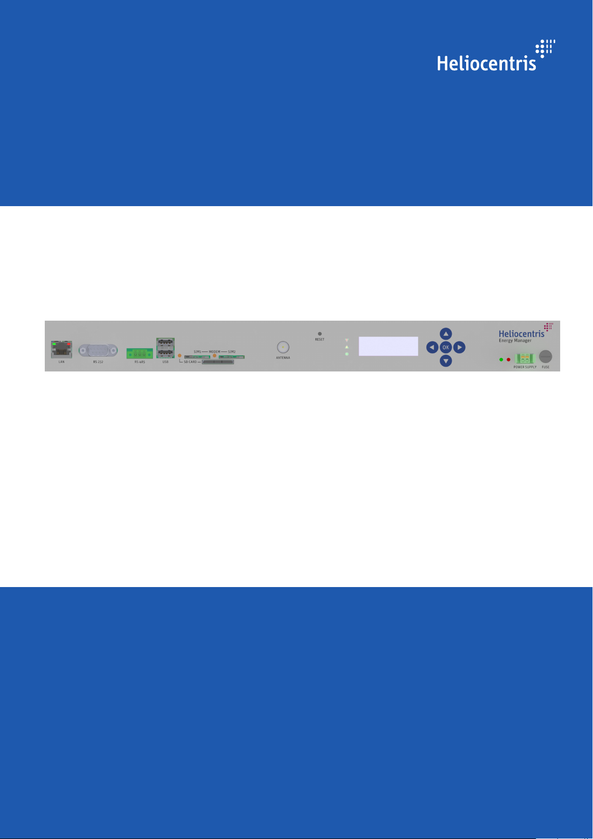
3.1.1 Front Side
The elements shown in Figure 3-1 are located on the front side of the
Energy Manager:
Figure 3-1 The front of Energy Manager
1Reset
2LED system status
3LCD
4Control keys
5Fastening hole right (2x)
6Main fuse
7Power supply port
8Power supply LED
9SD card holder
10SD card LED
11Fastening hole left (2x)
12LAN port
13RS 232 port (non isolated)
14RS 485 port (non isolated)
15 USB port (2x)
16 SIM 1 card holder
17Modem LED
18 SIM 2 card holder
19Antenna port
Energy Manager 2.0 - Instruction Manual 15
Components
Reset button
Reset button for a manual reset of the system. See How to Shut Down and
Restart Energy Manager on page 79.
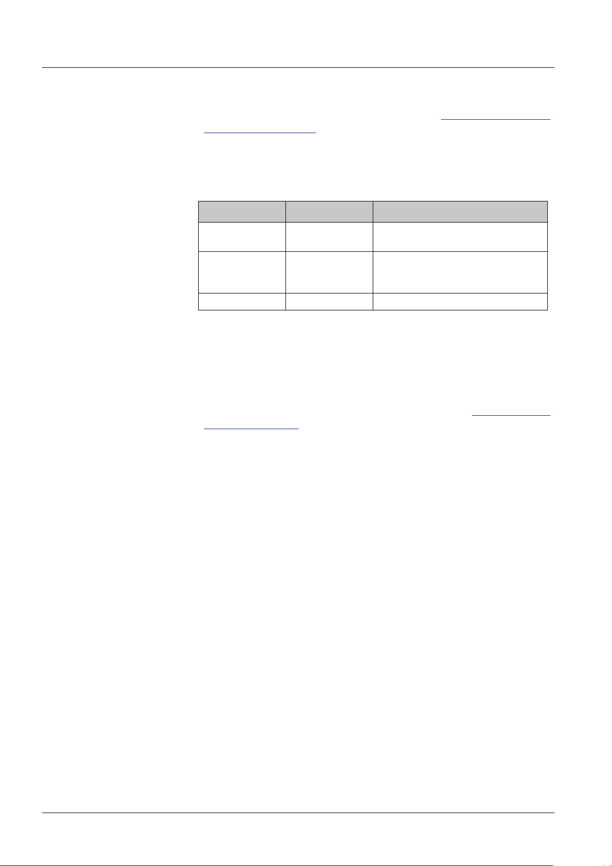
System Status LED
The LED (light-emitting diode) indicates the system status by using the
following symbols and colors:
Symbol Color Description
Red Critical system status: one of the
installed modules is in error status.
Yellow System is still in operating, but
requires attention e. g., warning or
maintenance.
Green No unit in error or warning status
Table 3-1 LED display
Liquid Crystal Display
The Liquid Crystal Display (LCD) comprises 4 lines of 20 characters to
display menu functions, system information and events.
Control Keys
The control keys serve to navigate in the LCD menu. See Operating Areas
of the Control Panel on page 31.
Fastening Hole
4 fastening holes to attach the Energy Manager to the rack
Main Fuse
Fuse to safeguard the power supply
Power Supply Port and LED
Port that supplies the power to the Energy Manager. The LED is green
when power is supplied. In case of incorrect polarity, it is red.
SD card holder and LED
Slot in which to insert SD memory card. The LED illuminates briefly each
time the SD card is accessed.
LAN Port
Port for RJ-45 LAN and Ethernet
RS232 Port
Non isolated RS232 interface
RS 485 Port
Non isolated RS485 interface
Modem LED
Light-emitting diode showing mode and status of the GPRS modem. The
LED illuminates briefly each time the modem is sending data.
16 Energy Manager 2.0 - Instruction Manual

Components
USB 2.0 Port
2 USB flash drive ports
SIM Card Holder
2 holders to insert SIM card
Antenna Port
Port for antenna of the GPRS modem
Energy Manager 2.0 - Instruction Manual 17

Components
3.1.2 Back Side
The I/O Panel is attached to the Energy Manager with a 128-pin plug
connector. It provides ports for analog or digital inputs. All connecting
points on the back side are shown in Figure 3-2.
Figure 3-2 Energy Manager rear side
1Digital input (8x)
2Relay (8x)
3Attachment screw right (2x)
4Handle right
5RS 232 port (isolated)
6RS 485 port (isolated)
7CAN bus port (isolated)
8Cable guide
9Grounding connection
10Analog input single ended (9x)
11Handle left
12 Attachment screw left (2x)
13Input PT1000 temperature sensor (5x)
14 PWM port (2x)
15 Analog Input Battery differential
ended (5x)
TIP
The I/O Panel ports and PIN assignments are also printed on the cover of
the device in order to facilitate assignment when working from the device’s
front side.
Back Side Viewed from Above
The elements needed for proper and stable cable connections are shown
in Figure 3-3.
Figure 3-3 Energy Manager back side viewed from above
1Handle (right and left)
2Shielding clamp
3Cable fastener (4x)
4Screw for I/O Panel (4x)
18 Energy Manager 2.0 - Instruction Manual

Components
3.2 Energy Manager Software Modules
The Energy Manager is comprised of various modules that adapt to the
customer’s needs. The modules are related to specific hardware
components and implemented into the Energy Manager and configurated
by Heliocentris when agreed to by the customer.
TIP
This chapter describes the Energy Manager software in its entirety. Only a
part of the described software modules and functions may be implemented
for your system.
The following overview includes all available modules. This overview does
not represent every customized solution.
Aircon Management (AIRCON)
The aircon management module controls the connected air conditioners.
The air conditioners are switched on and off depending on the measured
temperature and selected control algorithm. Different aircon units can be
cascaded in order to start one air conditioner after the other depending
on the required cooling capacity. The runtime of the air conditioners is
logged. Up to 6 air conditioners can be implemented.
Battery Management (BATT)
The battery management module controls the charging and discharging
of the connected batteries. It monitors battery state variables such as
voltage and current of the entire battery string, symmetry voltage, state of
charge, state of health, depth of discharge, capacity, and battery
temperature. Up to 12 strings can be implemented.
BUS
The units of the BUS module give access to measured data, alarms, status
information and parameter settings of 3rd party controllers attached to the
Energy Manager e.g. via SNMP, Modbus or proprietary protocols. Up to
30 bus units can be implemented.
Hydrogen
The hydrogen fuel management module monitors the data concerning
the hydrogen tank such as measured tank level and remaining runtime.
Up to 2 hydrogen tanks can be implemented.
Fuel Cell Management (FCELL)
The fuel cell management module controls the fuel cell. Depending on the
system status, the fuel cell is switched on or off.
The fuel cell state is monitored, including variables concerning the fuel
cell controller such as voltage, current or inlet cabinet pressure. 1 fuel cell
can be implemented.
Solar
The solar module monitors the solar panels. It monitors voltage, current or
irradiation and variables such as power and azimuth angle. Up to 6 solar
units can be implemented.
Wind
Energy Manager 2.0 - Instruction Manual 19

Components
The wind module monitors the wind turbine. It monitors voltage, current or
wind speed. Up to 4 Wind units can be implemented.
IOB
The IOB module enables access to data measured by the sensors and
actuators attached to the I/O panel of the Energy Manager and Extension
Boards. Up to 30 IOB modules can be implemented.
IOB4
The IOB4 module enables access to the data of measured by sensors
and actuators attached to the I/O panel of the Energy Manager. AIU
rules can be defined for the relay outputs available on the I/O board. The
port selection and calibration data for the analog inputs are stored in this
module. Up to 1 IOB4 module can be implemented. IOB4 is available
only for Energy Manager V 1.x.
IOM 3
The IOM3 module enables access to AIU rules that can be defined for the
relay outputs of the I/O board.
Up to 1 IOM3 can be implemented. IOM3 is available only for Energy
Manager V 1.x.
Free Cooling Unit Module (FCU)
The free cooling module controls the free cooling unit, which is used to
cool a shelter with ambient air. Indoor and outdoor temperature levels are
constantly compared. Up to 2 free cooling units can be implemented.
Fuel Cell Unit (FCunit)
The fuel cell unit module monitors data of a specific fuel cell unit such as
the generated power and alarms. Up to 4 fuel cell units can be
implemented.
Fuel Management (FUEL)
The diesel fuel management module monitors data related to the fuel tank
such as the measured tank level and related variables including fuel loss,
fuel refill, and total consumption. 1 Fuel tank can be implemented.
Genset Management (GEN)
The Genset management module controls the diesel generator.
Depending on the system status, the generator is switched on or off. In
order to increase Genset efficiency, maintenance, and reliability, the
runtime can be split between different generators. Up to 2 gensets can be
implemented.
Several generator state variables are monitored, including the starter
battery voltage, and variables dependent upon the generator controller
hardware such as the coolant level, coolant temperature, and oil
pressure. Optionally, a generator oil management system can be installed
and controlled.
20 Energy Manager 2.0 - Instruction Manual
Table of contents
Other Heliocentris Power Supply manuals

Popular Power Supply manuals by other brands

Videx
Videx 520MR Installation instruction

Poppstar
Poppstar 1008821 Instructions for use

TDK-Lambda
TDK-Lambda LZS-A1000-3 Installation, operation and maintenance manual

TDK-Lambda
TDK-Lambda 500A instruction manual

Calira
Calira EVS 17/07-DS/IU operating instructions

Monacor
Monacor PS-12CCD instruction manual


