Acome XP-LR512 RT User manual

DMX Wireless Transceiver
XP-LR512 RT
User Manual
2015.06.11
毅丰
受控正本

Specification
Input Voltage: AC 100-240V 50/60Hz
Power Consumption: 5W
Wireless frequency: 2.4GHz
Receive range: 300m
Weight: 0.6Kgs
Dimension: 194 x 100 x 127 mm
1A

Control Panel
Signal quality indicators
For the Receiver, it shows
the signal strength; for the
Transmitter, only one
indicator on all the time.
Function
Press to link with, or
unlink from another
unit.
RX/TX switch
Select Receiver or
Transmitter.
Status Indicators
RF Link on Transmitter:
On: Linked.
Fast flashing: Linking.
Slow flashing: Unlinked, or linked
but no DMX present.
RF Link on Receiver:
On: Linked
Fast flashing: Linking
Slow flashing: Linked but no DMX
present
Off: Unlinked
DMX: On when DMX is present
POWER: On when power applied
2A

Operation Indications
When operating, the units show different indications depending on
its mode and link status:
Transmitter when not linked.
Receiver when not linked.
Transmitter when linking.
Receiver when linking.
Transmitter showing a healthy
link with a Receiver.
Receiver showing a healthy link
with a Transmitter.
3A

Rear Panel Connections
Optional Accessories
For XP-LR512 RT, below three groups of accessories can be
selected:
A. Hanging suspender x 1, Fixed Plate for hanging x 1
B. Fixed plate for wall-hang x 1
C. Fixed plate A x 2, Fixed plate B x 2, M4 x 10 Hex screw x 4
DMX In
5-pin XLR input
DMX Out
5-pin XLR output
Power In
DC12V Power Input
4A

Mounting
1. Hanging in the truss
Put the fixed plate into the side slot of the fixture from the side
hole. Screw the clamp (not included) via the screw and nut onto
the hanging suspender. Fix the hanging suspender and the fixed
plate via the quick-lock fasten. Hang the combination in the truss.
2. Wall-hang
Slide the fixed plate into the slots in the surface of the fixture.
Hang the fixture on the wall.
5A

3. Fixed in the equipment cabinet
Put the fixed plates A into the side slots of the fixture. Combine
fixed plate A with fixed plate B via M4 x 10 Hex screws. Mount the
combination in the equipment cabinet via the screws.
6A

Operation
Connect with the other XP-LR512 RT:
1. Ensure the antenna is connected for all XP-LR512 RT.
2. Connect XP-LR512 RT with DMX console and connect the other
XP-LR512 RT with the fixtures.
3. Power on all the fixtures.
4. Select TX mode (Transmitter) or RX mode (Receiver) for all the
XP-LR512 RT.
5. On the transmitter, press and release the Function button. The
transmitter will search for any unlinked receivers. Its RF Link
indicator will fast flash for 10 seconds. If the RF Link indicator
changes to a steady on-state, it means they linked successfully.
If the indicator changes to flash slowly, it means fail.
6. Press and hold the Function button for more than 3 seconds to
unlink it from the other XP-LR512 RT.
7A

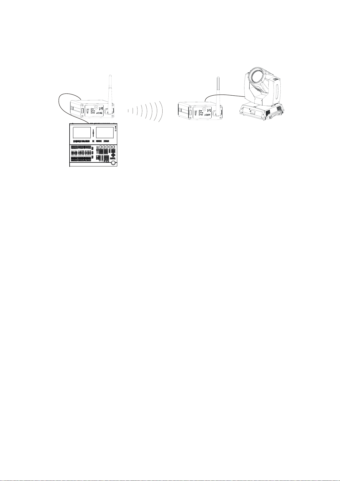
Connect with the wireless control fixture:
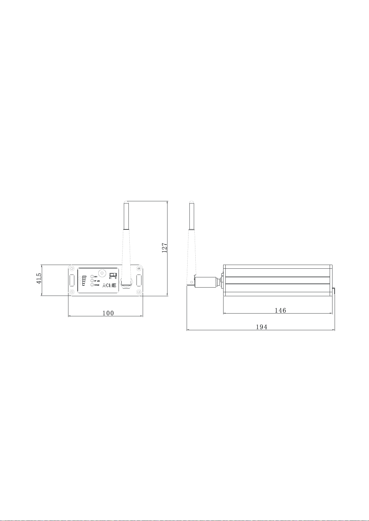
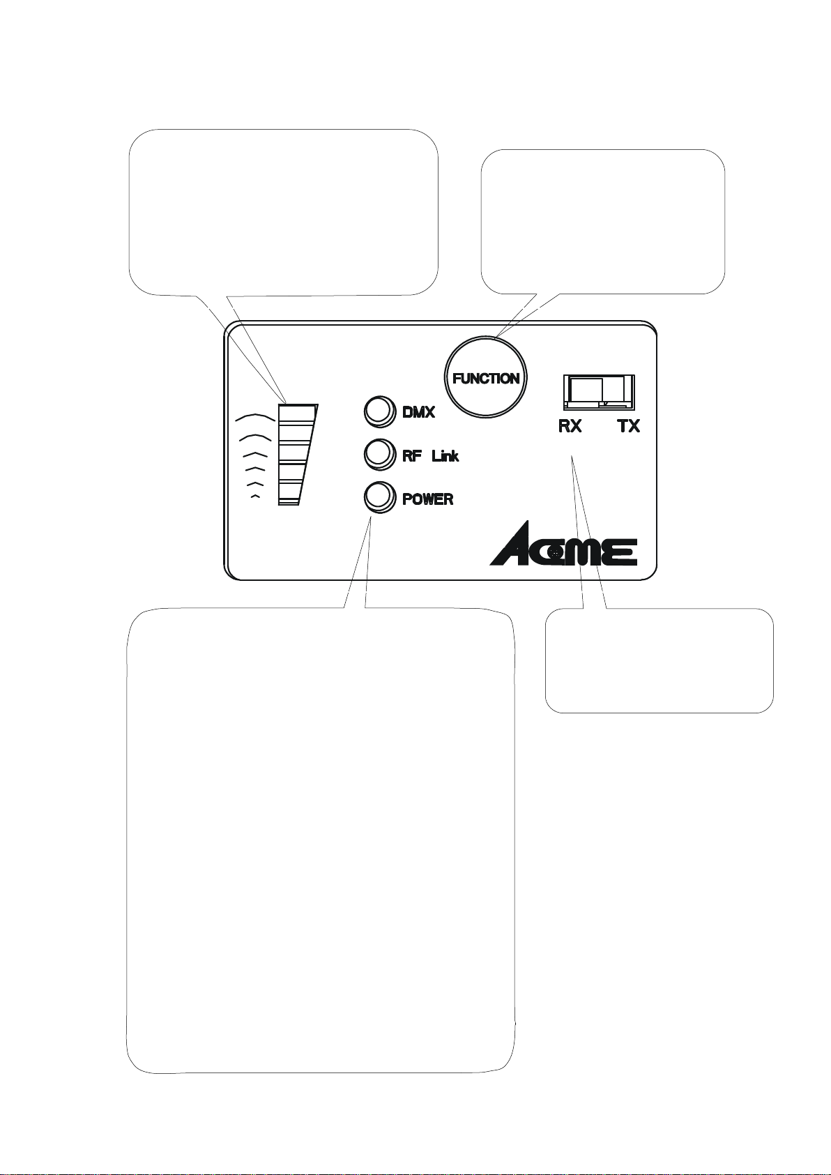
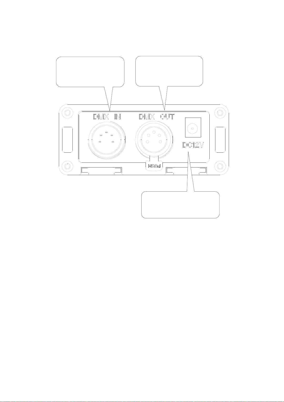
1. Ensure the antenna is connected for the XP-LR512 RT.
2. Connect XP-LR512 RT with DMX console.
3. Power on all the fixtures.
4. Select TX mode (Transmitter) for the XP-LR512 RT.
5. Set wireless mode for the wireless control fixture via the menu.
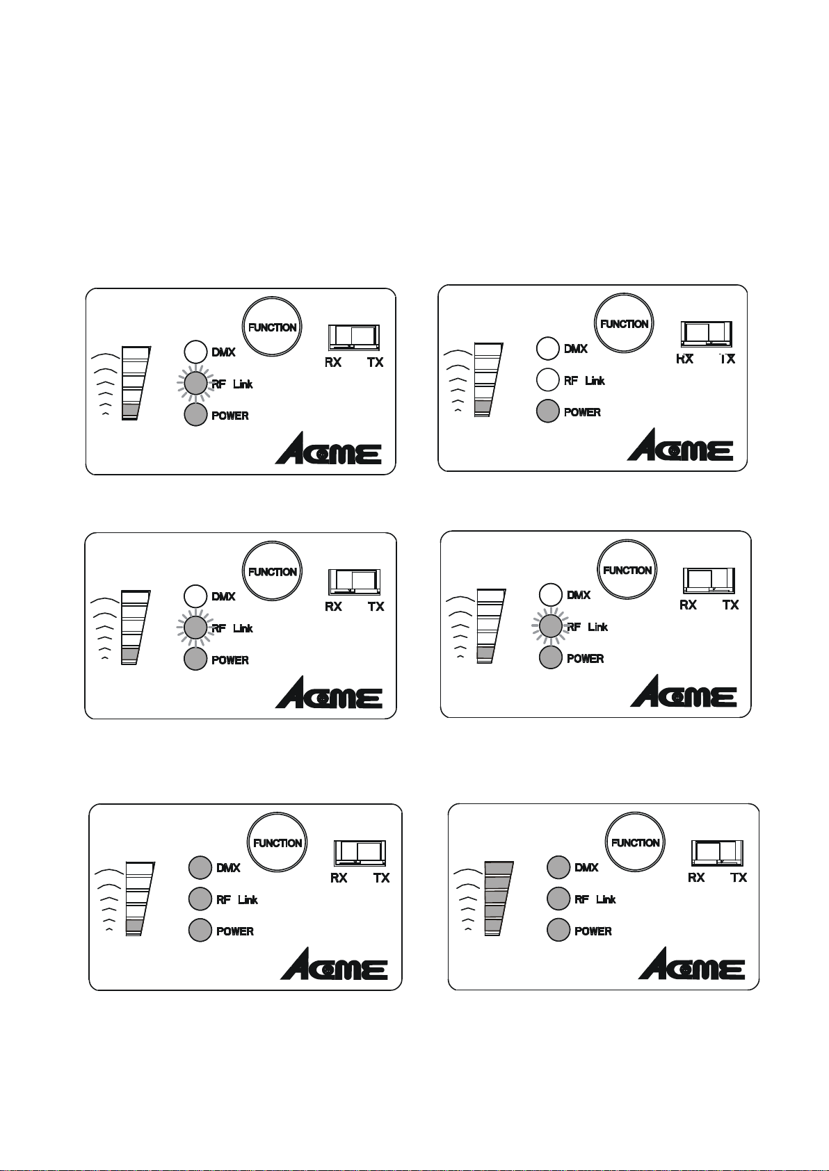
6. On the transmitter, press and release the Function button. The
transmitter will search for any unlinked receivers. Its RF Link
indicator will fast flash for 10 seconds. If the RF Link indicator
changes to a steady on-state, it means they linked successfully.
If the indicator changes to flash slowly, it means fail.
7. For the wireless control fixtures, cancel the wireless mode via
the menu to unlink it from the XP-LR512 RT; on the transmitter,
press the hold its Function button for more than 3 seconds to
unlink all of its receivers.
8A

To optimize range and performance:
Keep antennas upright;
Maintain the Transmitter to Receiver line of sight;
Elevate the units above any crowds;
Elevation above ground increases range;
Keep away from large metal objects.
Maintenance
Clean the front transparent cover at least every 1-2 months. Use a
moist, lint-free cloth. Never use alcohol or solvents!
9A

Declaration of Conformity
We declare that our products (lighting equipments) comply
with the following specification and bears CE mark in
accordance with the provision of the Electromagnetic
Compatibility (EMC) Directive 89/336/EEC.
EN55103-1: 2009 ; EN55103-2: 2009; EN62471: 2008;
EN61000-3-2: 2006 + A1:2009 + A2:2009; EN61000-3-3:
2008.
&
Harmonized Standard
EN60598-2-17:1989 + A2:1991; EN60598-1:2008+ A11: 2009
EN 62471:2008; EN 62493: 2010
Safety of household and similar electrical appliances
Part 1: General requirements
10A

Innovation, Quality, Performance
11A
Table of contents