NiceRF LoRa-CC68 Owner's manual


www.nicerf.com LoRa-CC68
NiceRF Wireless Technology Co., Ltd. Rev 1.0
- 2 -
Catalogue
1.Overview ..................................................................................................................................................................- 3 -
2.Features..................................................................................................................................................................... - 3 -
3.Applications..............................................................................................................................................................- 3 -
4.Electrical Characteristics(@Vcc=3.3v ANT connected to 50 ohm load) .................................................................- 4 -
5.Typical application circuit ........................................................................................................................................- 4 -
6.Module performance index....................................................................................................................................... - 5 -
7.Pin definition ............................................................................................................................................................- 7 -
8. Communication Antenna .........................................................................................................................................- 8 -
9.Mechanical Dimensions(Unit:mm)...........................................................................................................................- 8 -
10.Product order information....................................................................................................................................... - 9 -
11.Common problem ...................................................................................................................................................- 9 -
Appendix 1:SMD Reflow Chart ................................................................................................................................- 10 -
Appendix 2:Demo Board........................................................................................................................................... - 11 -
Note: Revision History
Revision
Date
Comment
V1.0
2021-06
First release
www.nicerf.com LoRa-CC68
NiceRF Wireless Technology Co., Ltd. Rev 1.0
- 3 -
1.Overview
The LoRa-CC68 wireless module uses Semtech's LLCC68 device, ultra-low receive current and sleep
current, and sensitivity of -129dBm. Built-in 64KHz crystal oscillator can wake up the microcontroller
periodically under low power consumption. The module antenna switch is integrated and controlled by
the chip, which saves the resources of the external MCU. The compact size and 8~10dBm output power
have great advantages in IoT and battery-powered applications.
LoRa-CC68 comply with lead-free craft in production and testing and meets RoHS and Reach standards.
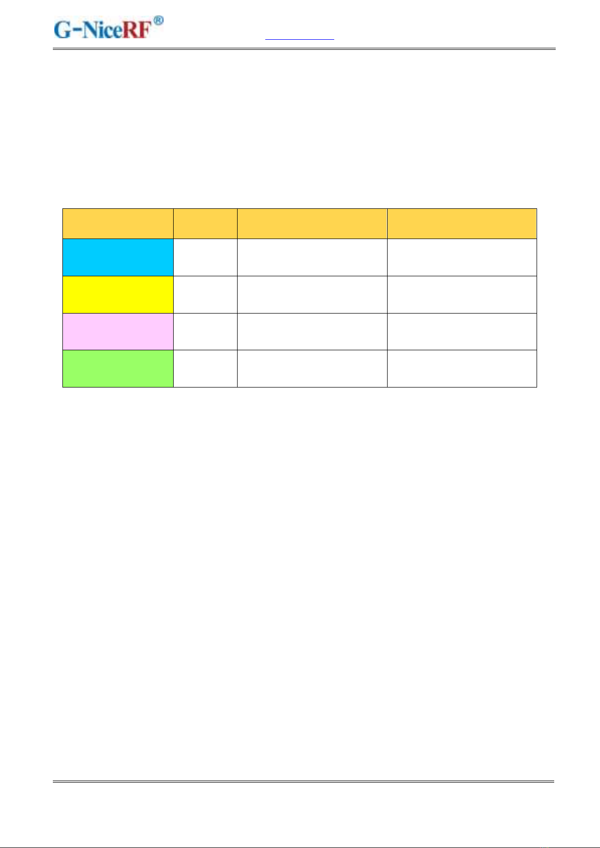
Module
Chip
Frequency Band
Crystal
LoRa-CC68-868-T
LLCC68
Center 868 MHz
1ppm Industrial grade
crystal oscillator
LoRa-CC68-915-T
LLCC68
Center 915 MHz
1ppm Industrial grade
crystal oscillator
LoRa-CC68-868
LLCC68
Center 868 MHz
10ppm Industrial grade
crystal oscillator
LoRa-CC68-915
LLCC68
Center 915 MHz
10ppm Industrial grade
crystal oscillator
2.Features
255 bytes FiFo
Data transfer rate:
0.6-300 Kbps @FSK
1.76-62.5 Kbps @Lora
Frequency Range:868/915 MHz
Sensitivity:-129dBm @LoRa
Maximum output power:8~10 dBm
Industrial grade high precision crystal oscillator
LoRa,(G)FSK
Applications
Industrial meter reading
Parking lot sensor management
Industrial automation
Agricultural sensor
Smart city
Remote control
Street lights
Logistics management
Environmental sensor
Health products
Security products
Warehouse management

www.nicerf.com LoRa-CC68
NiceRF Wireless Technology Co., Ltd. Rev 1.0
- 4 -
4.Electrical Characteristics(@Vcc=3.3v ANT connected to 50 ohm load)
★Note: The default shipment is ordinary crystal oscillator version. If needs, the TCXO crystal
oscillator version can also be customized.
Parameter
Min.
Typ.
Max.
Unit
Condition
Operation Condition
Working voltage
1.8
3.3
3.7
V
Temperature range
-40
25
85
℃
Current Consumption
RX current
< 5
mA
@ crystal oscillator
TX current
< 130
mA
@868MHz @915MHz
< 110
mA
@433MHz @490MHz
Sleep current
1.9
uA
OFF mode (SLEEP mode with cold start)
All blocks off
2.3
uA
SLEEP mode (SLEEP mode with warm start)
Configuration retained
2.9
uA
SLEEP mode (SLEEP mode with warm start)
Configuration retained + RC64k
0.56
mA
STDBY_RC mode ,RC13M, XOSC OFF
2.35
mA
STDBY_XOSC mode ,XOSC ON
RF Parameter
Frequency range
400
433
450
MHz
@433MHz
470
490
510
MHz
@490MHz
848
868
888
MHz
@868MHz
900
915
940
MHz
@915MHz
Output power
-15
22
dBm
Receiving sensitivity
-129
dBm
@LoRa BW=250KHz_SF = 10_CR=4/5
5.Typical application circuit
www.nicerf.com LoRa-CC68
NiceRF Wireless Technology Co., Ltd. Rev 1.0
- 7 -
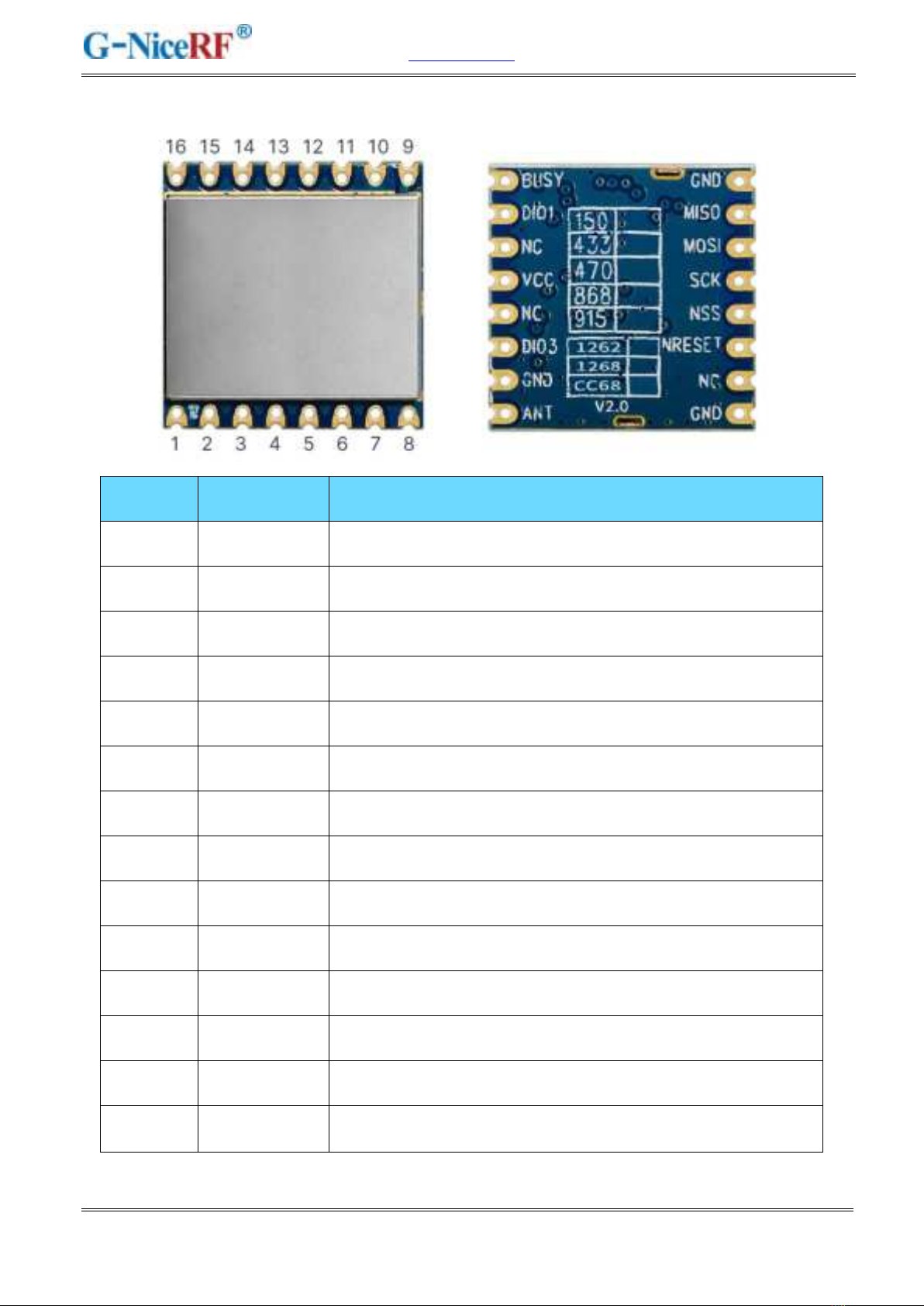
6.Pin definition
Pin NO.
Pin name
Description
1
GND
Power ground
2
MISO
SPI Output for SPI data
3
MOSI
SPI Input for SPI data
4
SCK
Serial clock for SPI interface
5
NSS
SPI enable
6
NRESET
Reset input
7、12、14
NC
Empty
8
GND
Power ground
9
ANT
Connect with 50 ohm coaxial antenna
10
GND
Power ground
11
DIO3
Digital I/O
13
VCC
Connected power supply(default3.3V)
15
DIO1
Digital I/O
16
BUSY
Used for status indication, see datasheet for details.
www.nicerf.com LoRa-CC68
NiceRF Wireless Technology Co., Ltd. Rev 1.0
- 8 -
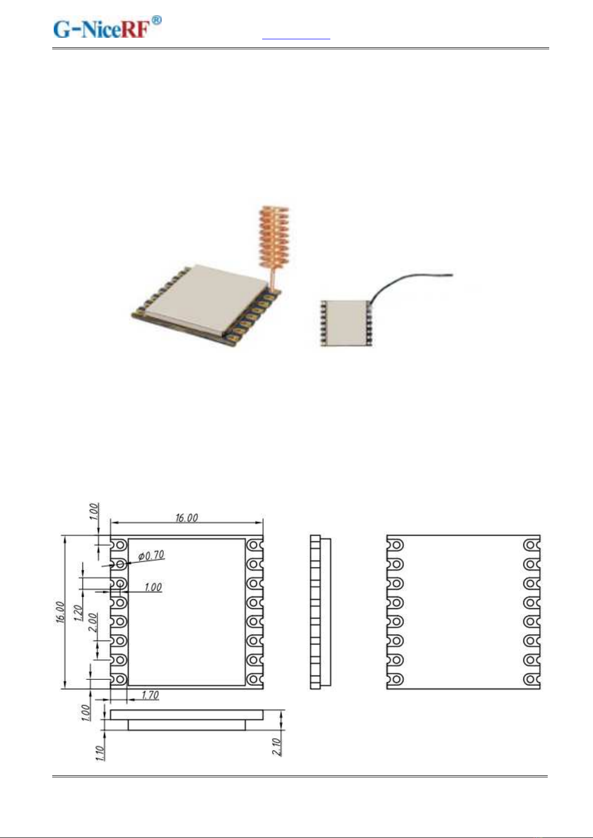
7. Communication Antenna
Antenna is very important for RF communication, its performance will affect the communication
directly. To ensure module in the best performance, we suggest to use the our antenna.
★To ensure modules get the best performance, user must obey the following principles when using
the antennas:
Put the antenna away from the ground and obstacles as possible as you could;
If you choose the sucker antenna, pull straight the lead wire as possible as it can be, the sucker
under arches should be attached on the metal object.
8.Mechanical Dimensions(Unit:mm)
www.nicerf.com LoRa-CC68
NiceRF Wireless Technology Co., Ltd. Rev 1.0
- 9 -
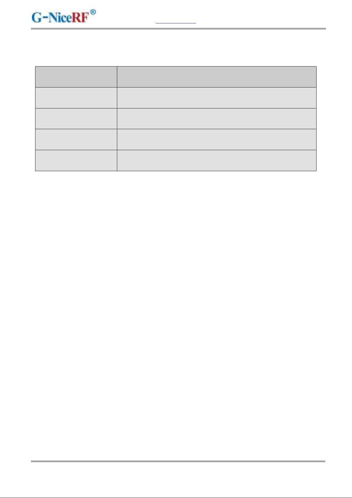
9.Product order information
For example: If the customer needs 868MHz Frequency, the order no. shall be LoRa-CC68-868.
Product Name
Description
LoRa-CC68-433
LLCC68 chip. Working frequency 433MHz
LoRa-CC68-490
LLCC68 chip. Working frequency 490MHz
LoRa-CC68-868
LLCC68 chip. Working frequency 868MHz
LoRa-CC68-915
LLCC68 chip., Working frequency 915MHz
11.Common problem
a) Why can't the normal communication between the modules?
1) The power connection is wrong and the module is not working normally;
2) Check whether the frequency bands of each module and other RF parameters are
consistent;
3) Whether the module is damaged.
b) Why is the transmission distance not far?
1) The power supply ripple is too large;
2) The antenna type is not matched or installed incorrectly;
3) Surrounding co-channel interference;
4) The surrounding environment is harsh and there are strong interference sources.

www.nicerf.com LoRa-CC68
NiceRF Wireless Technology Co., Ltd. Rev 1.0
- 10 -
Appendix 1:SMD Reflow Chart
We recommend you should obey the IPC related standards in setting the reflow profile:

www.nicerf.com LoRa-CC68
NiceRF Wireless Technology Co., Ltd. Rev 1.0
- 11 -
Appendix 2:Demo Board
The module is equipped with a standard DEMO board for customer to debug the program and test
distance. The power supply voltage range: 3.3V~6.0V. It shows as below:
The LCD Full Segment is as below:
The users can set the parameters of the RF module such as frequency /transmitter power /
transmission data rate through the buttons.

www.nicerf.com LoRa-CC68
NiceRF Wireless Technology Co., Ltd. Rev 1.0
- 12 -
Working Mode
1) Tx normal mode: send data packets regularly (in the setting mode, data packets will not be sent
temporarily);
2) Rx normal mode: Power on and enter the receiving state, receive data packets, and then send out
the correctly received data packets;
3) Tx Test Mode: RF module continuously transmit signal;
4) Rx Test Mode: RF module is always in Rx mode;
5) Standby Mode: RF module is always in standby state.
Button Operation
1) [SET] Button
Press the key to enter the setting mode. If the last parameter is set, the key will exit the setting mode.
2) UP /Down Button
In setting mode,press to modify the corresponding setting parameters.
Note: The DEMO board has FLASH memory inside, all the setting parameters will behave
automatically and keep unchanged even power-off.
www.nicerf.com LoRa-CC68
NiceRF Wireless Technology Co., Ltd. Rev 1.0
- 13 -
ATTENTION
This device is intended only for OEM integrators under the following conditions:
1) The antenna must be installed such that 20 cm is maintained between the antenna and users, and
2) This device and its antenna(s) must not be co‐located with any other transmitters except in
accordance with FCC multi‐transmitter product procedures. Referring to the multi‐transmitter
policy, multiple transmitter(s) and module(s) can be operated simultaneously without C2P. 3) For all
products market in US, OEM has to limit the Operating Frequency: 902-928MHz by supplied
firmware programming tool. OEM shall not supply any tool or info to the end‐user regarding to
Regulatory Domain change. USERS MANUAL OF THE END PRODUCT: In the user manual of the
end product, the end user has to be informed to keep at least 20cm separation with the antenna while
this end product is installed and operated. The end user has to be informed that the FCC radio‐
frequency exposure guidelines for an uncontrolled environment can be satisfied. The end user has to
also be informed that any changes or modifications not expressly approved by the manufacturer could
void the user's authority to operate this equipment. If the size of the end product is smaller than
8x10cm, then additional FCC part 15.19 statement is required to be available in the users manual: This
device complies with Part 15 of FCC rules. Operation is subject to the following two conditions: (1)
this device may not cause harmful interference and (2) this device must accept any interference
received, including interference that may cause undesired operation.
FCC WARNING
This device complies with part 15 of the FCC Rules. Operation is subject to the condition
that this device does not cause harmful interference (1) this device may not cause harmful
interference, and (2) this device must accept any interference received, including interference
that may cause undesired operation. Any changes or modifications not expressly approved by
the party responsible for compliance could void the user's authority to operate the equipment.
NOTE: This equipment has been tested and found to comply with the limits for a Class B digital
device, pursuant to Part 15 of the FCC Rules. These limits are designed to provide reasonable
protection against harmful interference in a residential installation. This equipment generate, uses
and can radiate radio frequency energy and, if not installed and used in accordance with the
instructions, may cause harmful interference to radio communications. However, there is no
guarantee that interference will not occur in a particular installation. If this equipment does
cause harmful interference to radio or television reception, which can be determined by turning the
equipment off and on, the user is encouraged to try to correct the

www.nicerf.com LoRa-CC68
NiceRF Wireless Technology Co., Ltd. Rev 1.0
- 14 -
interference by one or more of the following measures:
-- Reorient or relocate the receiving antenna.
-- Increase the separation between the equipment and receiver.
-- Connect the equipment into an outlet on a circuit different from that to which the receiver is
connected.
-- Consult the dealer or an experienced radio/TV technician for help.
Antennas
The LoRa-CC68 is an LoRa Module beams signals and communicates with its antenna, which is Wire
antenna&Spring antenna. The Wire antenna&Spring antenna gain is 2dBi
LABEL OF THE END PRODUCT
The final end product must be labeled in a visible area with the following: Host must Contains FCC ID:
2AD66-CC68-915. If the size of the end product is larger than 8x10cm, then the following FCC part 15.19
statement has to also be available on the label: This device complies with Part 15 of FCC rules. Operation is
subject to the following two conditions: (1) this device may not cause harmful interference and (2) this
device must accept any interference received, including interference that may cause undesired operation.
Information on test modes and additional testing requirements Data transfer module demo board can control
the EUT work in RF test mode at specified test channel. Additional testing, Part 15 Subpart B disclaimer The
module without unintentional-radiator digital circuit, so the module does not required an evaluation by FCC
Part 15 Subpart B. The host should be evaluated by the FCC Subpart B.
This manual suits for next models
4
Table of contents
Other NiceRF Transceiver manuals


