aconno ACD52832 User manual

- Made in germany -
MANUAL
ACD52832
Development Kit for Bluetooth Smart, ANT and 2.4 GHz
applications

www.aconno.com
August 5, 2016
The information contained in this document is the property of aconno GmbH and should not be disclosed to any third party without written permission.
Specification are subject to change without notice. V.1.1 © aconno GmbH 2016
2
ACD52832
Development Kit for Bluetooth Smart, ANT and
2.4 GHz applications
The aconno ACD52832 brings the speed and the simplicity of software development to
hardware and IoT. Our development board and our module are designed to support you
starting from the first prototype until the production. It empowers you to create smart,
connected Bluetooth devices.

www.aconno.com
August 5, 2016
The information contained in this document is the property of aconno GmbH and should not be disclosed to any third party without written permission.
Specification are subject to change without notice. V.1.1 © aconno GmbH 2016
3
Table of Contents
1.(Introduction(...................................................................................................................(4!
1.1.(Purpose(of(the(Board(............................................................................................................(4!
1.2.(Features(of(the(Board(...........................................................................................................(5!
2.(Getting(started(...............................................................................................................(6!
2.1(Electrostatic(warning(.............................................................................................................(6!
2.2(Requirements(........................................................................................................................(6!
2.3(Powering(up(the(ACD52832(board(for(the(first(time(...............................................................(7!
2.4(Programming(the(ACD52832(board(........................................................................................(8!
3.(The(Board(–(overview(...................................................................................................(11!
3.1(Overview(of(the(board(.........................................................................................................(11!
3.2(The(ACN52832(Bluetooth(Smart(Module(.............................................................................(12!
4.(Connection(pinout(–(peripherals(and(jumper((((description(...........................................(14!
4.1.(Jumper(Blocks(.....................................................................................................................(14!
4.2.(Expansion(Header(...............................................................................................................(16!
5:(On-Board(Features(.......................................................................................................(17!
5.1.(Inertial(Module(...................................................................................................................(18!
5.2.(EP(Display(...........................................................................................................................(20!
5.3.(Temperature(Sensor(...........................................................................................................(22!
5.4.(Light(Sensitive(Sensor(.........................................................................................................(23!
5.5.(IR-Emitter(...........................................................................................................................(24!
5.6.(PWM-Servo(Outputs(...........................................................................................................(25!
5.7.(User(Interfaces(...................................................................................................................(27!
5.8.(ADC(Potentiometer(............................................................................................................(29!
5.9.(Relay(Outputs(.....................................................................................................................(30!
5.10.(Buzzer(...............................................................................................................................(31!
5.11.(Segger(J-Link(OB(programmer(...........................................................................................(31!
5.12.(Power(Supply(and(Battery(Charger(...................................................................................(33!
6.(Mechanical(Dimensions(................................................................................................(35!
7.(Revision(History(............................................................................................................(36!
8.(Contact(Information(.....................................................................................................(37!
www.aconno.com
August 5, 2016
The information contained in this document is the property of aconno GmbH and should not be disclosed to any third party without written permission.
Specification are subject to change without notice. V.1.1 © aconno GmbH 2016
4
1. Introduction
Thank you for choosing the ACD52832 development board from aconno! We believe it
is the most feature complete Bluetooth smart development board out there.
This document is a user’s guide for the aconno ACD52832 starting with a general
overview and a list of the board’s features.
We hope you enjoy developing with it as much as we enjoyed developing it!
1.1. Purpose of the Board
The ACD52832 is as a development board for the aconno ACN52832 Bluetooth Low
Energy module which incorporates the highly powerful and energy efficient Nordic
Semiconductor nRF52832 SoC. To give the makers of tomorrow an ultimate
development platform for future IoT devices, various on-board sensors, input devices
and a graphical HiRes electronic paper display are supplied with the board.

www.aconno.com
August 5, 2016
The information contained in this document is the property of aconno GmbH and should not be disclosed to any third party without written permission.
Specification are subject to change without notice. V.1.1 © aconno GmbH 2016
5
1.2. Features of the Board
• ACN52832 2.4 GHz module, featuring the Nordic Semiconductor nRF52832 SoC.
• 9 degrees of freedom inertial module which contains a 3D accelerometer,
a 3D gyroscope and a 3D magnetometer
• Graphical high resolution electronic paper display with 200x200 pixels
resolution and 184 dpi pixel density
• Integrated Texas Instruments USB Li-Ion battery charger with up to 1.5A
charging current and automatically battery - USB power supply changeover.
• Temperature sensor with temperature range between -40°C and 125°C with ±
4°C accuracy
• Light sensitive sensor
• IR-emitter
• Piezo buzzer
• Digital joystick
• Two LEDs
• Two push buttons
• Potentiometer for ADC values
• Pin-header with seven I/O –ports
• Two potential free relay outputs
• Two PWM controlled servo outputs

www.aconno.com
August 5, 2016
The information contained in this document is the property of aconno GmbH and should not be disclosed to any third party without written permission.
Specification are subject to change without notice. V.1.1 © aconno GmbH 2016
6
2. Getting started
This section helps you setting up the ACD5282 development board for the first time.
Here you can find the hardware and software required to operate the board.
Moreover it shows the procedure to power up the board and the description of the
default board behavior.
Please consider first the electrostatic warning to avoid damaging the board.
2.1 Electrostatic warning
The ACD52832 board is shipped in a protective anti-static package. The board must not
be exposed to high electrostatic potentials. A grounding strap or similar protective
device should be worn when handling the board. Avoid touching the component pins or
any other metallic elements.
2.2 Requirements
In order to power up the ACD52832 board, only the supplied USB cable and a PC/ Mac
with the proper software are required.
Optionally you can connect a Li-Ion or a Li-Po battery to start the charging process
immediately after connecting the ACD52832 board to a PC/ Mac.

www.aconno.com
August 5, 2016
The information contained in this document is the property of aconno GmbH and should not be disclosed to any third party without written permission.
Specification are subject to change without notice. V.1.1 © aconno GmbH 2016
7
2.3 Powering up the ACD52832 board for the first time
1. Connect the ACD52832 board through the supplied USB cable with a PC or Mac and
turn on the power switch.
2. Two new USB devices should appear: The J-Link programming interface and a mass
storage device called “J-Link”
The mass storage device called “J-Link” is used as a drag & drop target for instant
programming with a corresponding *.hex file. The other device serves as a programming
interface for IDE Software such as ARM Keil. In order to use the second device, drivers
are required for the Segger J-Link device. These are delivered with most of the available
IDEs. Otherwise, the operating system will automatically search for drivers.
3. Upon initial powering, the board’s white LED “LD6”, next to the the power switch, will
turn on and the green debug LED will start and keep flashing. After the drivers are
installed, the debug LED will remain lit. A flashing debug LED means that the board was
not recognized by the PC/Mac.
www.aconno.com
August 5, 2016
The information contained in this document is the property of aconno GmbH and should not be disclosed to any third party without written permission.
Specification are subject to change without notice. V.1.1 © aconno GmbH 2016
8
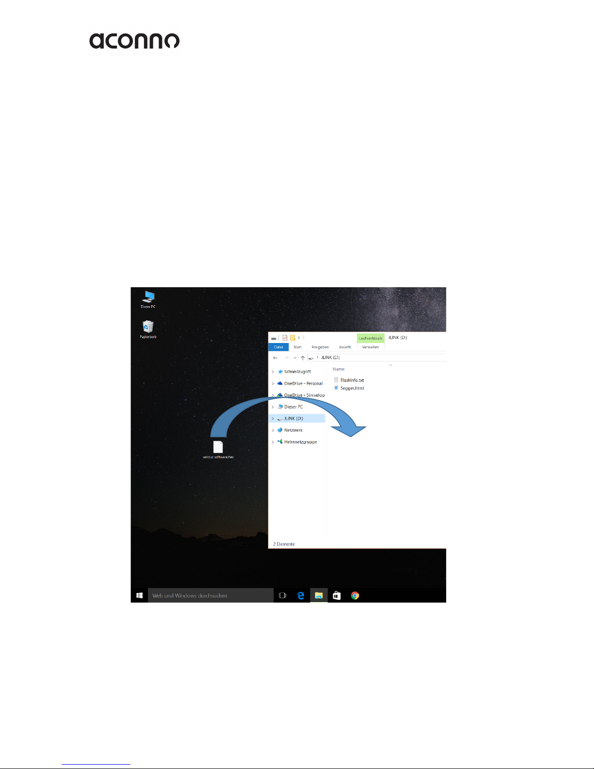
2.4 Programming the ACD52832 board
Since the ACD52832 board incorporates a genuine Segger J-Link debugging device with
drag & drop programming functionality, there are two ways of programming the
ACD52832: Using drag & drop without an IDE or within an IDE.
Without an IDE you can create your firmware e.g. using the mbed online developing
tool. After you created the *.hex file, simple put it on to the “J-Link” called mass storage
device.
During the programming process, the J-Link device will shortly disappear. When it
shows up again, the programming process is finished and your board is ready to go.
Picture 1: Programming with drag & drop
www.aconno.com
August 5, 2016
The information contained in this document is the property of aconno GmbH and should not be disclosed to any third party without written permission.
Specification are subject to change without notice. V.1.1 © aconno GmbH 2016
9
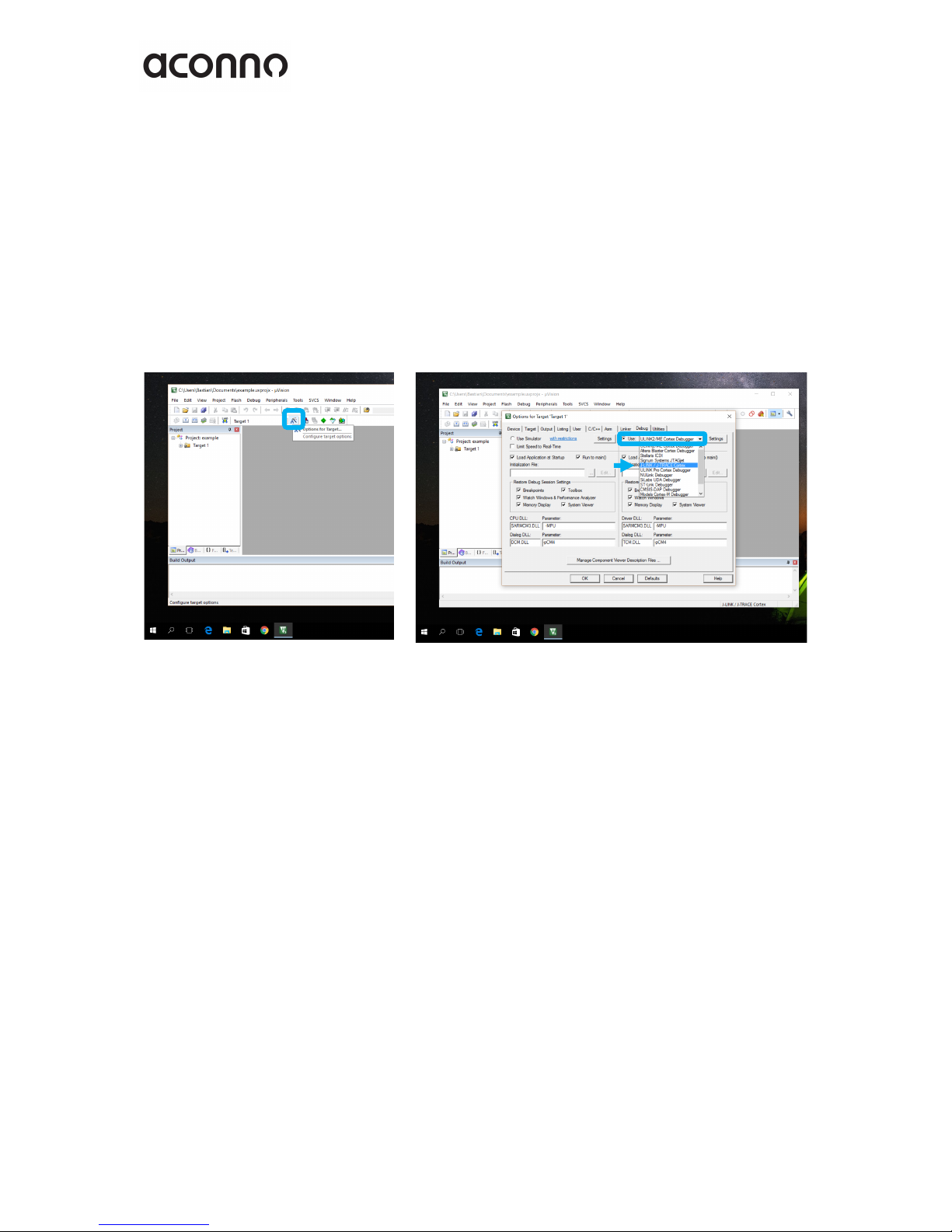
Programming with an IDE depends very much on which one you are using. aconno
recommends the usage of the ARM Keil development platform since it has a broad
support base among the different development and maker platforms.
In Keil the ACD52832 is automatically recognised. The only thing you have to do is to
choose the J-Link device from the available programming standards.
Go to “Options for Target” window and choose the “debug” card.
Once there, choose the “use:” List button and select the “J-Link / J-Trace Cortex” entry.
Picture 2: Selection within an IDE
That’s it. You are now ready to go and program your ACD52832 board!
You can test if the connection of the J-Link programmer is stable. Simply click on the
“Settings” Button on the right side of the “Use:” select bar.

www.aconno.com
August 5, 2016
The information contained in this document is the property of aconno GmbH and should not be disclosed to any third party without written permission.
Specification are subject to change without notice. V.1.1 © aconno GmbH 2016
10
Here you can see and change various settings like connection speeds. You can e.g. reset
states. What you should see is a serial number in the “Serial” field.
If you don’t see a number, please check your USB connection and drivers.
Close the Window and start to explore the ACD52832. If you have your program, just
click on the “Load” icon and your program will be automatically downloaded to the
board.
Picture 3: Settings of the J-Link programmer
www.aconno.com
August 5, 2016
The information contained in this document is the property of aconno GmbH and should not be disclosed to any third party without written permission.
Specification are subject to change without notice. V.1.1 © aconno GmbH 2016
11
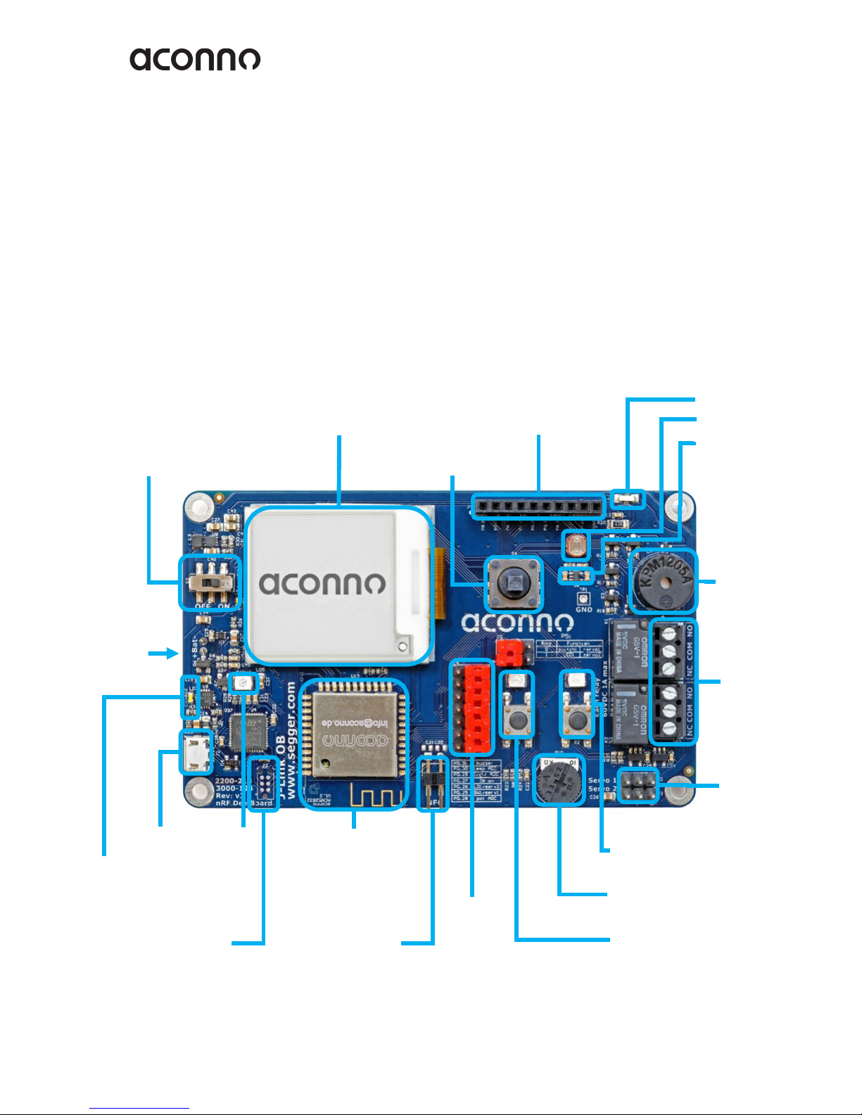
3. The Board – overview
Here we show the main components of the board. Please note that the descriptions
below do not necessarily match with the actual terms, which you can find and check on
the aconno ACD52832 board itself.
3.1 Overview of the board
Jumper
Blocks
NFC
Antenna
Connector
J-Link
LED1 &
Switch 1 1
Relay
Outputs
Buzzer
Servo
Outputs
LED2 & Switch 2 1
Potentiometer
EP Display
Power Switch
USB Port
Charging LED
Debug
LED
aconno
ACN52832
Light
Sensor
Expansion Header
Joystick
IR LED
Temp. Sensor
Battery
connector

www.aconno.com
August 5, 2016
The information contained in this document is the property of aconno GmbH and should not be disclosed to any third party without written permission.
Specification are subject to change without notice. V.1.1 © aconno GmbH 2016
12
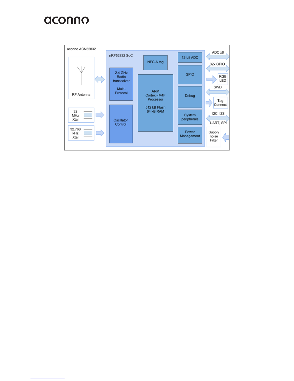
3.2 The ACN52832 Bluetooth Smart Module
The heart of the ACD52832 board is the ACN52832 module, which incorporates the
highly integrated nRF52832 SoC from Nordic Semiconductor. It is equipped with an
ARM Cortex M4F processing core and a 2.4 GHz radio module and is fully compatible
with the Bluetooth Smart (former BLE) standard. Its capabilities are tailored for the
upcoming demands of sophisticated IoT devices where small size, low power,
application performance and radio-range are essential.
Features of the ACN52832 module:
• 32-bit ARM© Cortex™ M4F high
performance 64 MHz processor core
• 512kB flash
• 64 kB RAM
• 2.4 GHz RF module with Bluetooth
Smart and ANT+ compatibility
• Up to 32 GPIOs with flexible
module pin mapping
• On-board RGB LED
• Programmable peripherals for CPU-
less operation
• SPI / UART / TWI (I2C)
• 200 ksps 12-bit ADC
• Low power comparator
• I2S and PDM peripherals for audio
• Quadrature demodulator
• -20 dBm to +4 dBm output power
• Ultra-low power consumption
• Temperature Range: -40°C to +85°C
• Wide supply voltage range: 1.7V to
3.6V
• NFC-A Tag for OOB Bluetooth Smart
pairing and “wakeup on field”
www.aconno.com
August 5, 2016
The information contained in this document is the property of aconno GmbH and should not be disclosed to any third party without written permission.
Specification are subject to change without notice. V.1.1 © aconno GmbH 2016
13
Picture 2: Inside the ACN52832
www.aconno.com
August 5, 2016
The information contained in this document is the property of aconno GmbH and should not be disclosed to any third party without written permission.
Specification are subject to change without notice. V.1.1 © aconno GmbH 2016
14
4. Connection pinout – peripherals and jumper
description
The following chapter describes the jumper header and expansion header pinouts and
their functions.
4.1. Jumper Blocks
The ACD52832 is equipped with various jumper blocks to give the developer total
control of the board features. In order to use the on-board devices and expansion pin
headers correctly, we recommend that the developer acquires a good understanding of
jumper blocks first.
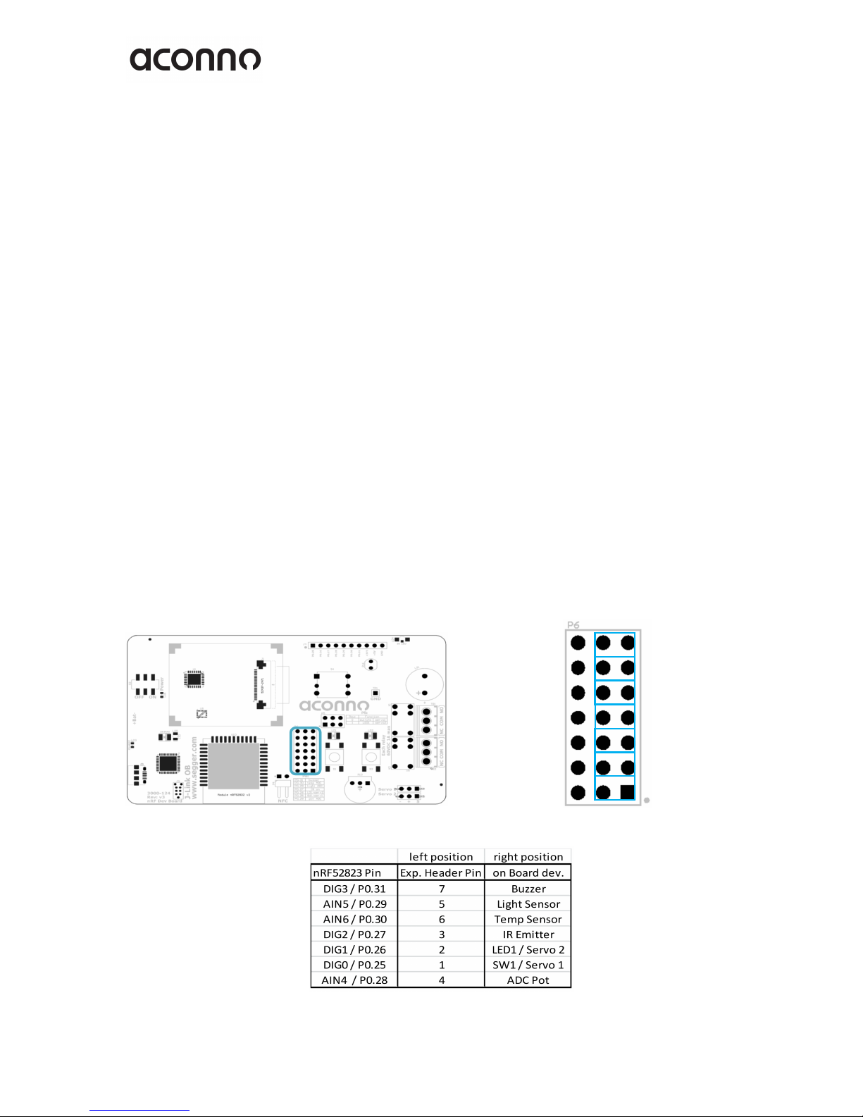
Jumper'block'P6
The P6 jumper block gives you the choice to either use an on-board component (i.e. the
readout of the light sensor) or an expansion header pin on a certain controller pin.The
jumper in the position left connects the corresponding on-board device, in the position
right it routes the controller pin to the expansion header J4.
Picture 3: Position on the board
Picture 4: Jumper block P6

www.aconno.com
August 5, 2016
The information contained in this document is the property of aconno GmbH and should not be disclosed to any third party without written permission.
Specification are subject to change without notice. V.1.1 © aconno GmbH 2016
15
Jumper block P5
The jumper block P5 determines the usage of the controller pins P0.25 and P0.26 if
these were selected through jumper block P6 for internal usage.It is possible to use
pin P0.25 as source for the Servo 1 output or as input for the switch SW1.For pin P0.26
the choice is between a source for Servo 2 or LED2.
Picture 5: Position on the board
Picture 6: Jumper block P5

www.aconno.com
August 5, 2016
The information contained in this document is the property of aconno GmbH and should not be disclosed to any third party without written permission.
Specification are subject to change without notice. V.1.1 © aconno GmbH 2016
16
4.2. Expansion Header
The expansion header is intended to expose the GPIOs of the ACN52832 module to
external circuits. Supply voltages and a ground connection are also available at this
header.
Picture 7: Position on the board

www.aconno.com
August 5, 2016
The information contained in this document is the property of aconno GmbH and should not be disclosed to any third party without written permission.
Specification are subject to change without notice. V.1.1 © aconno GmbH 2016
17
5: On-Board Features
The ACD52832 incorporates a variety of on-board features in order to speed up the
development process of devices which make use of the aconno ACN52832 module.In
the following subchapters each device will be described with corresponding ACN52832
module connections and requirements.
The connections of the ACN52832 module are shown below.The ACN52832 is supplied
through the +3.3V rail of the board and has direct connections to the I²C-, EPD, battery
sense- and J-Link debug devices.The NFC-pins are connected to a 2.54 mm header and
allow the connection of an NFC field coil.There are pads on the board near to the
connector to equip 0603 capacitors according to the used field coil.
Note: The pull up resistors for the I²C bus are 4.7 kOhm resistors which are supplied
also through the +3.3V rail.
Picture 8: ACN52832 Connections

www.aconno.com
August 5, 2016
The information contained in this document is the property of aconno GmbH and should not be disclosed to any third party without written permission.
Specification are subject to change without notice. V.1.1 © aconno GmbH 2016
18
5.1. Inertial Module
The ACD52832 incorporates a highly integrated iNEMO inertial module by
STMicroelectronics.It allows the measurement of acceleration, angular moving rate
and magnetic field strength in all three dimensions.
The measurement range is selectable and depends on your application:
±2 / ±4 / ±6 / ±8 g linear acceleration full scale
±4 / ±8 / ±12 / ±16 gauss magnetic field strength full scale
±245 / ±500 / ±2000 dps angular rate full scale
The communication between the nRF52832 and the inertial module is realised through
the I²C interface and various interrupt lines which can also be configured through the
I²C bus.
Gyroscope / accelerometer address: 1101 010
Magnetometer address: 0011 100
For more information see the component manufacturer’s
datasheet:http://www.st.com/resource/en/datasheet/lsm9ds0.pdf
Picture 4: Position on the board

www.aconno.com
August 5, 2016
The information contained in this document is the property of aconno GmbH and should not be disclosed to any third party without written permission.
Specification are subject to change without notice. V.1.1 © aconno GmbH 2016
19
Picture 5: Inertial module circuit

www.aconno.com
August 5, 2016
The information contained in this document is the property of aconno GmbH and should not be disclosed to any third party without written permission.
Specification are subject to change without notice. V.1.1 © aconno GmbH 2016
20
5.2. EP Display
The ACD52832 features a graphical HiRes, easy to use, 1.54 inch electronic paper
display with nearly no power consumption.
No power supply is needed to display screen content. The screen content is maintained
even in case of a power loss.
Power is only needed to refresh the screen content.The resolution is 200 x 200 pixels
at a density of 184 dpi. It also features high contrast, ultra-wide viewing angle and high
reflectance.
Picture 7: Electronic paper Display
Picture 6: Position on the board
Table of contents


