Coapt GEN2 User manual

Gen2 EVALUATION KIT
Handbook
v1.0
© 2019
Coapt, LLC
222 W Ontario St., Suite 300
Chicago, IL 60654
844.262.7800 (toll free)
www.coaptengineering.com

1
Coapt LLC |222 W Ontario St, Suite 300, Chicago, IL 60654 USA |844.262.7800 |www.coaptengineering.com
CONTENTS
CONTENTS.............................................................................................................................. 1
USER ASSISTANCE & SAFETY ............................................................................................ 3
USER ASSISTANCE ....................................................................................................................................................................3
GENERAL WARNINGS AND PRECAUTIONS ................................................................................................................3
EVALUATION KIT OVERVIEW............................................................................................ 5
DESCRIPTION.............................................................................................................................................................................5
PURPOSE ......................................................................................................................................................................................5
INDICATIONS FOR USE .........................................................................................................................................................5
CONDITIONS FOR USE..........................................................................................................................................................6
LIMITATIONS..............................................................................................................................................................................6
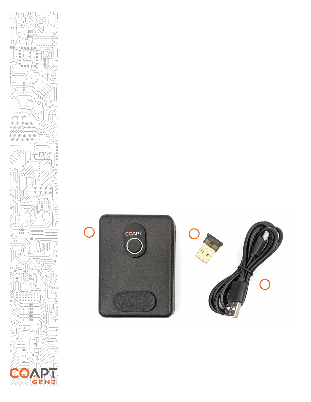
IN THE KIT...................................................................................................................................................................................6
ACCESSORIES .............................................................................................................................................................................7
EMG Interface Cable.............................................................................................................................................................7
Electrodes ................................................................................................................................................................................8
CLINICIAN GUIDE ................................................................................................................. 9
PATTERN RECOGNITION INTRODUCTION................................................................................................................9
MYOTESTING AND ELECTRODE PLACEMENT FOR PATTERN RECOGNITION..........................................10
Step 1: Discussion ................................................................................................................................................................11
Step 2: Palpation ...................................................................................................................................................................12
Step 3: Positioning Electrode Contacts..........................................................................................................................13
EVALUATION KIT INSTRUCTIONS ................................................................................. 15
CHARGING ...............................................................................................................................................................................15
POWERING ON.......................................................................................................................................................................15
CONNECTING AN EMG INTERFACE CABLE ..............................................................................................................16
BLUETOOTH CONNECTION............................................................................................................................................16
SOFTWARE/APPLICATION SETUP ...................................................................................................................................17
Installation..............................................................................................................................................................................17
Updates...................................................................................................................................................................................18
CALIBRATING PATTERN RECOGNTION CONTROL..............................................................................................18
Calibration Initialize/Reset.................................................................................................................................................18
Starting Calibration from the Software/Application ...................................................................................................19
Starting Calibration from the Evaluation Kit.................................................................................................................19
Full Sequence Calibration...................................................................................................................................................20
Single Motion Calibration...................................................................................................................................................22
CONTROL COACH..........................................................................................................................................................22
ADAPTIVE ADVANCE ......................................................................................................................................................23
COMPLETE CALIBRATE LED COLOR INDICATIONS...............................................................................................24
COMPLETE CONTROLROOM GEN2: USER INTERFACE APPLICATION................. 25
OVERVIEW.................................................................................................................................................................................25
COMPLETE CONTROLROOM ENVIRONMENTS .......................................................................................................25
Dashboard..............................................................................................................................................................................25
Connect..................................................................................................................................................................................26
Inputs.......................................................................................................................................................................................28
Calibrate .................................................................................................................................................................................30
Actuate ...................................................................................................................................................................................33
TROUBLESHOOTING ......................................................................................................... 35
PATTERN RECOGNITION TROUBLESHOOTING .....................................................................................................35
HARDWARE TROUBLESHOOTING ................................................................................................................................36

2
Coapt LLC |222 W Ontario St, Suite 300, Chicago, IL 60654 USA |844.262.7800 |www.coaptengineering.com
ADDITIONAL INFORMATION........................................................................................... 37
LIMITED US WARRANTY .....................................................................................................................................................37
EXTENDED WARRANTY.....................................................................................................................................................38
RETURNS....................................................................................................................................................................................38
PRODUCT RETURN POLICY..............................................................................................................................................38
TECHNICAL INFORMATION .............................................................................................................................................38
REGULATORY INFORMATION .........................................................................................................................................39

3
Coapt LLC |222 W Ontario St, Suite 300, Chicago, IL 60654 USA |844.262.7800 |www.coaptengineering.com
USER ASSISTANCE & SAFETY
USER ASSISTANCE
Contact your prosthetist if you have difficulty operating your device. You may also contact Coapt for
support (toll free) at 844-262-7800.
Additional information about connecting and using the Evaluation Kit may be found online at
www.coaptengineering.com
GENERAL WARNINGS AND PRECAUTIONS
For safety and to prevent damage to the Evaluation Kit, please read and adhere to all safety precautions
found in this handbook. In addition, please follow the safety guidelines found in the user manual(s) for
any connected electrodes and other devices. Failure to heed all warnings and precautions could cause
injury to the user, patient, damage to the device, or void the warranty. The following symbol definitions
pertain to warnings in this handbook and on all device labels.
SYMBOL DEFINITIONS
Warning regarding possible risk of severe accidents or injury.
Warning regarding possible risks of accident or injury.
Warning regarding possible damage to product or equipment.
Refer to Operating Instructions prior to use.
Read and follow safety instructions. Read this entire manual before operating the
Evaluation Kit. Failure to do so could result in suboptimal system performance, injury,
or damage to the device.
NEVER attempt to remove or modify the battery in any way. Maintenance,
repairs and upgrades may only be performed by Coapt, LLC. Unauthorized device
modification or disassembly could cause damage to the device resulting in device
malfunction, and injury to the user.
NO modifying or disassembling device. Do not disassemble componentry or
modify in any way. Maintenance, repairs and upgrades may only be performed by Coapt,
LLC. Unauthorized device modification or disassembly could cause damage to the
device resulting in device malfunction, and injury to the user.
Use with implanted electronic devices. Do not bring the Evaluation Kit into the
immediate proximity of active implanted devices (e.g., pacemakers, defibrillators) unless
assured by a qualified healthcare professional that it is safe to do so. Interference
between the Evaluation Kit and the implanted device could cause the implanted device
to malfunction.
Use near open flame. Use care when operating device near an open flame, and do
not allow device to remain directly over an open flame. Direct exposure to an open

4
Coapt LLC |222 W Ontario St, Suite 300, Chicago, IL 60654 USA |844.262.7800 |www.coaptengineering.com
flame may cause the device to exceed safe temperature limits and may cause device
malfunction and injury.
Exposure to extreme temperatures. Do not expose to extreme low (<-20ºC) or
high (>45ºC) temperatures. Exposure to extreme temperatures could cause damage to
the device and minor injury.
Use near sources of high radio frequency (RF) energy. Use caution when
operating the device in proximity to sources of high RF energy (e.g., broadcast antennas
or radar systems). Interference could cause malfunctioning of the device.
Use in a corrosive environment. Do not expose the device to excessive amounts
of corrosive substances (e.g., salt water, sweat) or clean with acetone, benzene or
similar solution. Exposure of electronics to corrosive substances can cause damage to
the device resulting in device malfunction, and minor injury to the user.
Exposure to excessive moisture, vibration, dust, or shock. Do not expose to
excessive moisture, liquid, dust, vibration or shock. Doing so can cause damage to the
device resulting in device malfunction, and minor injury to the user.
Crushing of device. Take care not to allow the device to become smashed or
crushed. Crushing of the device can cause device malfunction, and minor injury to the
user.
Use in areas of large static buildup. Take care when operating the device in areas
with large amounts of electrostatic buildup (e.g., very low humidity). Exposure to
electrostatic discharge can cause damage to the device resulting in device malfunction
and minor injury to the user.
Opening enclosures. Never open the Evaluation Kit
enclosure. Opening the
enclosure could cause permanent damage to the Evaluation Kit resulting in device
malfunction and minor injury to the user.
Use of heat guns. Do not bring a heat gun or other heating device into proximity to
the Evaluation Kit. Overheating can cause damage to the Evaluation Kit, resulting in
device malfunction and minor injury to the user.
Use with incorrect or incompatible electrodes. Make sure the Evaluation Kit is
only connected to a EMG Interface Cable referenced in this instruction manual. Use
with an EMG input that is incompatible with the system, may cause damage to and/or
malfunction of the device and could result in minor injury to the user.

5
Coapt LLC |222 W Ontario St, Suite 300, Chicago, IL 60654 USA |844.262.7800 |www.coaptengineering.com
EVALUATION KIT OVERVIEW
DESCRIPTION
The Coapt Evaluation Kit is a handheld clinical tool created with technology from the Coapt
COMPLETE CONTROL System Gen2. COMPLETE CONTROL employs pattern recognition
technology to revolutionize the way muscles’ bioelectrical activity (electromyogram, EMG) signals are
analyzed, recorded, and used for the control of upper limb prostheses.
The Evaluation Kit allows for visualization and evaluation of myoelectric signals generated from muscle
contractions. The Evaluation Kit also permits virtual practice and training for pattern recognition
myoelectric control.
Figure 1: Features of the Coapt Evaluation Kit
PURPOSE
The Coapt Evaluation Kit is intended to be used for the planning and/or practice phases of an upper
limb myoelectric prosthesis fitting with two main purposes:
1. The Evaluation Kit allows potential upper limb prosthesis users to “test drive” Coapt
COMPLETE CONTROL myoelectric pattern recognition technology. It permits visualization
of EMG control signals and enables control of a virtual prosthetic arm in real time using the
COMPLETE CONTROLROOM Gen2 user interface application. The Evaluation Kit can also
be used as a training tool to assist users in enhancing their function with pattern recognition
myoelectric control.
2. The Evaluation Kit assists with determining location of electrodes in the socket by allowing the
clinician to validate potential for pattern recognition myoelectric control. This enables efficient
planning of the prosthesis socket. With less time spent in the clinic searching for the best
muscle control sites, more time will be available for in-clinic functional practice.
INDICATIONS FOR USE
The Coapt Evaluation Kit is an accessory tool intended to be used during the planning and alignment
of myoelectric control contact locations for an upper limb prosthetic socket.
POWER ON/OFF
SWITCH
POWER ON LED
INDICATOR
COMPLETE
CALIBRATE BUTTON
COMPLETE COMMUNICATOR
BLUETOOTH USB DONGLE
EMG INTERFACE
PORT
AUX INTERFACE
PORT
MICRO-USB
CHARGING PORT
CHARGING STATUS
INDICATOR LED

6
Coapt LLC |222 W Ontario St, Suite 300, Chicago, IL 60654 USA |844.262.7800 |www.coaptengineering.com
CONDITIONS FOR USE
The Evaluation Kit was developed for clinical use and must not be used for unusual activities.
The Coapt Evaluation Kit should only be used by a trained and licensed medial professional or under
supervision of a trained and licensed medical professional.
See General Warnings and Precautions for more information regarding acceptable use conditions.
LIMITATIONS
Careful evaluation is required to determine if individuals with brachial plexopathy or high-level
amputations without targeted muscle reinnervation surgery could benefit from Coapt COMPLETE
CONTROL. The Coapt Evaluation Kit can aid in determining this.
IN THE KIT
The Coapt Evaluation kit is to be used in conjunction with a Coapt EMG Interface Cable (sold
separately) and the Coapt COMPLETE CONTROLROOM Gen2 user interface application.
The Coapt Evaluation Kit contains the following components:
1. Evaluation Kit main unit
2. COMPLETE COMMUNICATOR USB Bluetooth Dongle – provided with the
Evaluation Kit to enable Bluetooth connection to a personal computer
3. USB Charging Cable – micro-USB cable for main unit charging via a USB port or USB IEC
62133 certified external wall plug (wall plug not provided by Coapt)
Figure 2: Components of the Coapt Evaluation Kit
Accessories to the Evaluation Kit and not included but may be required:
1. EMG Interface Cable(s) (sold separately)
2. Coapt Dome Electrodes (if necessary, sold separately)
1
2
3

7
Coapt LLC |222 W Ontario St, Suite 300, Chicago, IL 60654 USA |844.262.7800 |www.coaptengineering.com
ACCESSORIES
EMG Interface Cable
When purchasing an Evaluation Kit, the EMG Interface Cable(s) are not included and must be ordered
separately. The Evaluation Kit is only compatible with Coapt EMG Interface Cable types shown in the
table below. Please contact a Coapt representative with any questions about EMG Interface Cable
types and uses.
EMG
INTERFACE
CABLE
PART
NUMBER DESCRIPTION
Standard Eyelets
EMG Interface
Cable
CCEE 17 ring/eyelet terminations for use with Coapt Dome Electrode Set
(p/n ELSA)
Snap Style EMG
Interface Cable
CCES 17 snap terminations for use with set of liner-snap electrode contacts
(sold by third party) or with disposable, self-adhesive snap contacts

8
Coapt LLC |222 W Ontario St, Suite 300, Chicago, IL 60654 USA |844.262.7800 |www.coaptengineering.com
Evaluation-Style
Cuff EMG Interface
Cable
CCEC Wrap-around, Velcro cuff for evaluation use with transradial and
small circumference transhumeral limbs
Osseointegration-
Style Cuff EMG
Interface Cable
CCEO Elastic cuff for definitive Osseointegration use only
Electrodes
Where the Evaluation Kit is used with an Eyelets style EMG Interface Cable (CCEE), Coapt
recommends the use of FDA cleared, non-filtering, passive, stainless-steel, electrode domes as EMG
contacts. Please contact a Coapt representative with any questions about use of other potentially
compatible electrodes.
PRODUCT
INFORMATION
RELATED PRODUCT
REGISTRATION 510(K)
Manufacturer: Coapt, LLC
Product Name: Dome
Electrodes (ELSA)
Part Number(s):
D37C13T4L50, ELSA
Proprietary Name: Dome Electrode
Registered Establishment Number: Coapt, LLC,
3010605876
Product Code and Regulation Number: GXY,
882.1320
K190416
Skin irritation.
Use of non-
biocompatible materials (or materials to which the user is
allergic) for electrode contacts may cause skin rash or
skin irritation. Ensure
electrode
contacts are made of biocompatible material and do not cause an allergic reaction.

9
Coapt LLC |222 W Ontario St, Suite 300, Chicago, IL 60654 USA |844.262.7800 |www.coaptengineering.com
CLINICIAN GUIDE
PATTERN RECOGNITION INTRODUCTION
WHAT IS PATTERN RECOGNITION?
Multiple muscles work together each time we move our arms and hands. The contractions of these
muscles create a pattern of activity that is unique to each movement. For example, the pattern of
forearm muscle activity for hand opening is different than the pattern for hand closing. Electrodes
placed on the skin over multiple muscle areas (which we often call “control sites”) can detect these
overall patterns of activity.
HOW IS PATTERN RECOGNITION AN IMPROVEMENT OVER STANDARD
MYOELECTRIC PROSTHESIS CONTROL?
Muscle signals contain a lot of information. Pattern recognition uses the combined information gathered
from all electrodes to control multiple prosthesis movements. In contrast, standard myoelectric
control only considers the signal level from one electrode to control each prosthesis movement. In
other words, standard myoelectric control is like listening to music and only knowing how loud the
sound is, while pattern recognition is like hearing what song is playing.
Key benefits of pattern recognition over standard myoelectric control include the following:
•Control motions are intuitive – With standard myoelectric control, users are often required to
make non-intuitive contractions to command prosthesis actions. A good example of this is
using wrist extension and flexion contractions to command a prosthetic hand to open and
close. With pattern recognition, natural intuitive control is possible: hand open and close
contractions will control the prosthetic hand, and wrist contractions will control the prosthetic
wrist.
•Mode switching is eliminated – With standard myoelectric control, muscle control sites are
limited because of the need for signal isolation. This typically means fewer control sites are
available than the desired prosthesis functions and users have to use “switches” to cycle
between prosthesis functions. Examples include using co-contractions of two control signals
to toggle between hand and wrist control or a physical/electrical switch the user must activate
with another movement of their body. With pattern recognition, users can directly control
each of their prosthesis’s motions without cumbersome and non-intuitive switching.
•Strong muscle contractions are not required – Pattern recognition has the advantage of being able
to utilize low intensity muscle contractions as needed. This is beneficial for standard
myoelectric control users who were required to elicit strong control contractions that tire
them out quickly.
•Enhanced proportional control – Because of the difficulty of isolating control sites with standard
myoelectric control, much of a user’s ability to modulate the intensity of their prosthesis’s
motor speed is often tuned out of the system. With pattern recognition, the system can take
full advantage of the user’s ability and relates a wide range of the muscle contraction intensities
to prosthesis speeds.
•Simplified electrode placement – With pattern recognition, there is much less need to search
for, or precisely place control site electrodes over exact muscle locations. This means less
time is spent myotesting for isolated signals; clinicians have freedom to place electrodes in
socket areas that promote fit and comfort; clinicians can use sockets/liners that may be
positioned differently upon each donning; the system is forgiving of changes due to muscle
fatigue; and many other benefits. With less time spent in the clinic searching for the muscle

10
Coapt LLC |222 W Ontario St, Suite 300, Chicago, IL 60654 USA |844.262.7800 |www.coaptengineering.com
control sites, time available for in-clinic functional practice with the prosthesis is increased –
thus helping users accept their prosthesis for increased at-home use.
•Powerful recalibration – With standard myoelectric control, changes in socket fit, user skin
condition, fatigue, mental state, battery health, and many other factors can diminish the user’s
function with their prosthesis. For many of these issues a repair visit or call to a prosthetist is
necessary, often resulting in time-consuming prosthesis adjustments and software resetting.
With pattern recognition, the control can adapt to changing conditions (such as those listed
above and many more) by means of re-calibration that the user can do quickly and efficiently
as needed – without travel and time with their clinician.
WHAT IS KEY TO MAKING PATTERN RECOGNITION FUNCTION AT ITS BEST?
Repetition Matters: Pattern recognition works best if the user can replicate the patterns of muscle signals
for each motion the same way each time. Each motion should “feel” the same each time the user
performs it.
Differentiation is Key: Pattern recognition requires the pattern of muscle signals to be different for each
distinct motion. Each motion should “feel” different from all other motions.
One at a Time: Only one motion can be performed at a time. The performance of
combined/simultaneous motions can temporarily confuse the system.
PRACTICING PATTERN RECOGNITION CONTROL
•No need for extra-hard muscle contractions. Contraction levels should be moderate – like a
comfortable handshake.
•Start slow and encourage patience. This new method of control can take a little time and
practice to get used to.
•Control is not position-based. Example: if a hand is commanded to close (and it does) and the
user then wishes to turn the wrist, they do not need to “hold” their hand closed while rotating
their wrist, as each motion is a separate activity.
•If control becomes erratic, ask the user to relax, close their eyes, and think back to the
“feeling” of all their motions. The system doesn’t forget the patterns it was most recently
calibrated with, so perhaps the user has changed the way they are performing muscle
contractions.
SUCCESSFUL USE OF PATTERN RECOGNITION CONTROL RELIES ON TWO
PRIORITIES:
1. Placing electrodes at locations that make reliable contact with the skin.
2. Good understanding of pattern recognition calibration by the user and the practitioner.
MYOTESTING AND ELECTRODE PLACEMENT FOR
PATTERN RECOGNITION
This section describes a 3-step approach to myotesting and electrode contact placement for pattern
recognition myoelectric prosthesis control. Pattern recognition utilizes the full spectrum of information
contained in multiple EMG signals – as opposed to traditional myoelectric control schemes which rely
on comparative amplitude information from singular EMG signals – and for ideal pattern recognition
performance, electrode contact locations are strategically planned for areas of reliable contact on the
residual limb. The following guidelines describe an approach to how this is accomplished through use
of the Coapt Evaluation Kit.

11
Coapt LLC |222 W Ontario St, Suite 300, Chicago, IL 60654 USA |844.262.7800 |www.coaptengineering.com
Step 1: Discussion
To begin planning for electrode placement for
pattern recognition, start with having a thorough
discussion with the user about their current
perceptions of missing limb movement and muscle
contractions. This discussion will encourage the
user to think about control in a new way. It is
important to discover what control motions the
user will find intuitive to use.
GOALS of the Discussion are to determine what
muscle contractions (motions) the user feels:
1. Are intuitive to use for prosthesis control.
2. Can be performed consistently.
3. Are unique for each intended prosthesis action.
DISCUSSION TIPS:
•A qualified practitioner should lead the discussion.
•Use demonstrations of the motions for the user to imagine and attempt.
•Ask questions to determine what movements the user can perceive and produce with their
phantom limb, such as:
o“Can you feel your hand? Which fingers can you feel you can move?”
o“Can you imagine making a fist? What about opening your hand with your fingers
spread apart?”
o“Does it feel like your hand is squeezing down on something?”
o“Do you feel like you can turn your wrist? Does your hand stay relaxed?”
o“Does your thumb move? How far? Which direction?”
o… and so on. Remember, the goal is to learn, together, what might be available for
control.
•Discuss one movement group at a time; i.e. discuss and practice hand open/close before moving
on to wrist motions.
•Encourage the user to mirror their perceived motions with their sound limb if possible.
•Begin discussing the most intuitive motions and add variations as needed; i.e. try natural hand
close for “hand close” and if the user has poor perception of hand close but good perception
of one specific finger (for example), try practicing the use of that finger perception for “hand
close.” In another example, if wrist rotation is difficult for the user to perceive, discuss if they
can perceive thumb or pinky finger ab/adduction to accentuate rotation.
•Focus on motions that are distinct and repeatable.
•Take considerable time with this process.
•Be patient and listen to the user.
•Perform this discussion in a relaxed environment.
•Generate a common vocabulary for motions.
•Incorporate the discussed and practiced motions into a home exercise program for pre-
prosthetic control.
•Encourage the user to make and hold the muscle contractions.
Figure 3: Clinical discussion for pattern recognition

12
Coapt LLC |222 W Ontario St, Suite 300, Chicago, IL 60654 USA |844.262.7800 |www.coaptengineering.com
Step 2: Palpation
The second stage of planning for electrode placement is to repeat the Discussion activities with the
user but do so while feeling for any underlying muscle activity from their residual limb. Palpation for
pattern recognition is NOT an exercise in finding one or two isolated myosites; instead, it is a process
to feel for all muscle activity areas including the subtle, the co-contracting, the unexpected, etc. The
practitioner should feel with as much of their hands as possible and avoid trying to pinpoint activity
using only fingertips.
GOALS of Palpation are to:
1. Feel for all “areas of interest” corresponding to any and all underlying muscle activity related
to the control motions.
2. Keep note/remember these “areas of interest” as good locations to place electrode contacts.
PALPATION TIPS:
•Grasp and cover as much of the user’s limb as possible; do not just use fingertips to feel.
•Have the user perform all the useful motions discovered during the Discussion phase.
oEncourage the user to make and hold medium, comfortable-intensity contractions.
oHave the user hold each contraction for about 3 seconds and relax between each.
•Feel for the overall muscle activity – like what the pattern recognition algorithm does – by
sensing the patterns of activity at multiple areas simultaneously.
•Do not only locate areas of strong, isolated contractions; instead sense all “areas of interest”.
•Do not ignore areas of slight/subtle/weak underlying muscle contraction.
•Note any unique and unexpected areas of underlying muscle contraction.
oFor transhumeral amputees this may mean unique muscle activity distal on the residual
limb.
•Encourage the user to practicing making and holding their muscle contractions.
•If the user tenses muscles quite hard for all motions, ask them to make contractions a little
more softly.
•If desired, make temporary markings on user’s residual limb to help remember areas of activity.
•Take time with this process.
•Be patient and listen to the user.
•Perform this exercise in a relaxed environment.
Figure 4: Clinical palpation activities for pattern recognition

13
Coapt LLC |222 W Ontario St, Suite 300, Chicago, IL 60654 USA |844.262.7800 |www.coaptengineering.com
Step 3: Positioning Electrode Contacts
If the Discussion and Palpation steps have been performed with care, most of the information required
to locate electrode contacts is known. Discussion helped to identify the intended control contractions
and Palpation was used to locate the corresponding areas of underlying muscle activity on the residual
limb. The Electrode contacts used for the evaluation will be placed on the residual limb to capture this
muscle contraction information.
GOALS of positioning electrode contacts are to:
1. Cover the areas of interest discovered during Palpation.
2. Plan accordingly for future socket/liner constraints.
PLANNING TIPS:
•Consider starting with locations that correspond to existing myosites for retrofitting existing
users.
•Identify locations to AVOID electrode contact, such as
oAreas that will lose electrode-to-skin contact during use.
oAreas outside of socket trim-lines or co-located with valves.
oAreas that have no underlying muscle (i.e. bone only).
oSensitive skin areas.
oAreas with active EMG during positional loading (e.g. deltoids, brachioradialis).
The Evaluation Kit connects to a Coapt EMG Interface Cable to evaluate eight EMG signal channels.
To make up a single EMG channel, a pair of passive electrode contacts work together and pick up an
oval-shaped area of muscle signal underlying these two contacts. The closer the two contacts are to
each other, the smaller the area of detected EMG and vice versa.
When using the Standard Eyelets (CCEE), Snaps (CCES), or Osseointegration-style Cuff (CCEO) EMG
Interface Cable, each EMG channel will have its own pair of electrode contact points, plus one contact
for system-wide reference/ground, making a total of 17 contact points.
When using the Evaluation-style Cuff (CCEC) EMG Interface Cable, EMG channels will share some
electrode contact points, plus one contact for system-wide reference/ground, making a total of 9
contact points.
Placing the Evaluation-style Cuff (CCEC) or Osseointegration-style Cuff (CCEO) EMG
Interface Cable:
For best results, clean and dampen underlying skin
areas before placing the cuff.
Fit the Evaluation-style cuff snugly around the most
muscular section of the limb being evaluated and
secure with the Velcro attachment.
Specific rotational position is not crucial but
consider aligning the connection cable with the
Ulna (below elbow) or laterally (above elbow) for
repeatability.
Figure 5: Evaluation-style Cuff EMG Interface Cable (CCEC)

14
Coapt LLC |222 W Ontario St, Suite 300, Chicago, IL 60654 USA |844.262.7800 |www.coaptengineering.com
Placing the Standard Eyelets (CCEE) or Snaps (CCES) EMG Interface Cable:
Contact Spacing – It is acceptable to position the two
electrode contacts for any EMG channel 30–60 mm apart.
This is helpful when fitting a larger residual limb – spacing the
contacts apart will ensure that all available EMG control
information is captured.
Contact-Pair Orientation – It is acceptable to place some of
the EMG channels off-axis from the underlying muscle
fiber direction.
This is helpful when fitting a residual limb with unique areas of
EMG interest, common for Targeted Muscle Reinnervation
patients. This can also be useful for geometrically unique and
congenital limb presentations.
Contact Sharing – It is acceptable to have a few of the EMG
channels share an electrode contact. Ensure the two wires
for the same EMG channel (common color wires) are
NOT sharing a single electrode contact. All wires must be
connected to an electrode contact.
This is helpful when fitting a smaller residual limb – sharing the
electrode contacts will limit the amount of electrode hardware
required while capturing all available EMG control information.
Single Reference (Ground) Contact – The COMPLETE
CONTROL System Gen2 requires a single electrode
contact for purposes of EMG reference/ground. This
contact should not be shared with any other EMG signal
wires. The reference contact should be positioned in a
location that maintains excellent electrode-skin contact.
General Symmetric Distribution – It is acceptable in some
cases to position electrode contacts in a symmetrical
arrangement. This is common for transhumeral Targeted
Muscle Reinnervation patients and some transradial
patients.
NOTE: Contact your Coapt representative with any questions about myotesting and/or electrode
placement. Coapt is willing and able to assist with placement instruction and suggestion – these can
often be accomplished by submitting socket and/or limb shape images to Coapt.
Figure 6
: Annotated examples of electrode placement
for pattern recognition
1
2
4
5
3
R
1
2
3
4
R
1
2
3
4
5
6
7
R
8
Figure 6
: Annotated examples of electrode placement
for pattern recognition

15
Coapt LLC |222 W Ontario St, Suite 300, Chicago, IL 60654 USA |844.262.7800 |www.coaptengineering.com
EVALUATION KIT INSTRUCTIONS
CHARGING
A micro-USB cable is provided with the Evaluation Kit for charging the internal battery of the main
unit. To charge the battery at any time, connect the USB 3.0 side of the cable to a USB computer port
or suitable USB wall-charging “brick” then connect the micro-USB side of the cable to the micro-USB
port on the side of the Evaluation Kit.
The Evaluation Kit requires 2.5-3 hours to fully charge from a fully depleted battery.
Figure 7: Evaluation Kit and micro-USB cable disconnected (Left) and connected/charging (Right)
The Charging Status Indicator LED Light is next to the Evaluation Kit’s micro-USB port has three
different colors:
CHARGING STATUS
INDICATOR LED
STATUS
Red Solid Low battery warning. Charge the Evaluation Kit.
Amber Solid Evaluation Kit is charging.
Green Solid Evaluation Kit is fully charged.
POWERING ON
To power on the Evaluation Kit, use the power switch located on the side of the main unit. The Power
ON LED light next to the power switch will illuminate orange and remain on when the Evaluation Kit
is powered on.

16
Coapt LLC |222 W Ontario St, Suite 300, Chicago, IL 60654 USA |844.262.7800 |www.coaptengineering.com
Figure 8: Evaluation Kit powered off (Left) and powered on showing the illuminated orange Power ON LED (Right)
When powered on, the LED light of the COMPLETE CALIBRATE Button on the top of the main unit
may also be illuminated. See the table in the COMPLETE CALIBRATE LED Color Indications section
for information on COMPLETE CALIBRATE LED colors.
The Evaluation Kit will operate for approximately 6 hours from a full charge.
CONNECTING AN EMG INTERFACE CABLE
The Coapt Evaluation Kit will need to be connected to a compatible EMG Interface Cable (see
Accessories section) for proper operation. All EMG Interface Cable types have the same mating
connector for attaching to the Evaluation Kit. This connector mates firmly to the EMG Interface Port
on the top of the Evaluation Kit.
1. Remove the black plastic EMG Interface Port cap.
2. Plug the connector end of the EMG Interface Cable to the EMG Interface Port with the label
side of the EMG Interface Cable connector facing away from the COMPLETE CALIBRATE
Button.
Figure 9: Connecting an EMG Interface Cable to the Evaluation Kit by removing the EMG Interface Port Cap (Left-to-Center) and
plugging in the connector end of the EMG Interface Cable to the EMG Interface Port (Center-to-Right)
BLUETOOTH CONNECTION
The Coapt Evaluation Kit communicates to the COMPLETE CONTROLROOM user interface
application via Bluetooth. To prepare this connection for a personal computer:
Do Not force improper connection. If the EMG Interface Cable connector is
forced in the wrong orientation, damage to the EMG Interface Cable and/or the
Evaluation Kit could result.

17
Coapt LLC |222 W Ontario St, Suite 300, Chicago, IL 60654 USA |844.262.7800 |www.coaptengineering.com
1. Remove the COMPLETE COMMUNICATOR USB Bluetooth Dongle from its holder pocket
in the top edge of the Evaluation Kit’s main unit.
2. Plug the COMPLETE COMMUNICATOR USB Bluetooth Dongle into a functioning USB port
on your personal computer.
Figure 10: Preparing for Bluetooth communication by removing the COMPLETE COMMUNICATOR USB Dongle from its Evaluation
Kit holder (Left-to-Center) and plugging it into a personal computer USB port (Right)
SOFTWARE/APPLICATION SETUP
The Evaluation Kit is designed to be used in conjunction with the COMPLETE CONTROLROOM
Gen2 user interface application. This is an easy-to-use user interface application for Windows PCs and
coming soon to iOS devices. See the comprehensive instructions in the COMPLETE
CONTROLROOM: USER INTERFACE APPLICATION section before using the
Evaluation Kit.
Installation
Windows PC
1. Visit https://www.coaptengineering.com/gen2setup and navigate to the COMPLETE
CONTROLROOM Gen2 download link to save the installer application file to the computer.
2. Navigate to the downloaded installer application file and double-click to begin.
3. Follow the install wizard directions.
4. Once the installation is complete, click on the desktop icon to use the COMPLETE
CONTROLROOM Gen2 application software as needed.
iOS
1. Once COMPLETE CONTROLROOM Gen2 is available for iOS devices, navigate from the
Home screen to App Store . To install apps, sign in with an Apple ID or create one.
2. To browse the App Store, tap Apps (at the bottom).
3. Search for the application by name, tap Search (at the bottom) then enter the name of the
app – COMPLETE CONTROLROOM.
4. Tap the app.
5. Tap GET then tap INSTALL.
•For a compatible iPhone with Face ID enabled, double-tap the Side button then look
at the screen to authenticate.
•For a compatible iPhone with Touch ID enabled, press the finger used for Touch ID
on the home buttonto authenticate.
6. If prompted, sign in to the iTunes Store to complete the install.

18
Coapt LLC |222 W Ontario St, Suite 300, Chicago, IL 60654 USA |844.262.7800 |www.coaptengineering.com
Updates
Windows PC
The COMPLETE CONTROLROOM Gen2 application will alert you when a critical update is available.
1. A pop-up window will ask if you want to install – select yes.
2. The update procedure will be initiated and will restart the COMPLETE CONTROLROOM
Gen2 application when complete.
iOS
When an update is available for the COMPLETE CONTROLROOM Gen2 application, the iOS device
should automatically initiate the update next time the application is opened.
Alternatively, iOS applications can be updated manually:
1. From the Home screen, tap App Store .
2. Tap Updates in the bottom right corner
3. Find COMPLETE CONTROLROOM Application and tap the Update button next to it.
Alternatively, tap Update All in the top right corner to update the COMPLETE
CONTROLROOM and other applications awaiting an update.
CALIBRATING PATTERN RECOGNTION CONTROL
Key to successful use of the pattern recognition capabilities of the Evaluation Kit is the ability to
conveniently calibrate or “train” the algorithms of the system. Pattern recognition needs to be
calibrated to learn the muscle signal patterns the user wants to use for control.
The Evaluation Kit provides calibration via the COMPLETE CONTROLROOM Gen2 user interface
application. Instead of a prosthesis moving and the user copying its actions (as done with COMPLETE
CONTROL System Gen2), a virtual arm and/or a displayed prompt of functions will guide the user
through collection of muscle signal patterns.
Calibration can be initiated either by the COMPLETE CALIBRATE Button on the top of the Evaluation
Kit main unit, or from within the COMPLETE CONTROLROOM Gen2 user interface application.
Calibration Initialize/Reset
Before any newly connected user calibrates with the Evaluation Kit for pattern recognition control,
the system should be initialized/reset to an initial, baseline state.
Initialize/Reset also provides a useful means that allows users to “start fresh” when pattern recognition
control is not adequate.
An initialized/reset starting state means the memory of ADAPTIVE ADVANCE will be set to an initial,
baseline state.
There are two ways to initialize/reset the system:
USING THE COMPLETE CALIBRATE BUTTON:
1. Press and hold the COMPLETE CALIBRATE Button on top of the Evaluation Kit main unit for
10 continuous seconds.

19
Coapt LLC |222 W Ontario St, Suite 300, Chicago, IL 60654 USA |844.262.7800 |www.coaptengineering.com
2. A short jingle will be played and the LED light on the COMPLETE CALIBRATE Button will
turn to solid magenta indicating the system was initialized/reset.
USING COMPLETE CONTROLROOM GEN2 USER INTERFACE APPLICATION:
1. Open the COMPLETE CONTROLROOM Gen2 user interface application and connect via
Bluetooth to an Evaluation Kit that is powered on.
2. Navigate to the Calibrate environment and click the cogwheel icon to access the settings pop-
up menu.
3. Locate and click the “Reset” button near the controls for ADAPTIVE ADVANCE.
4. The LED light on the Evaluation Kit’s COMPLETE CALIBRATE Button will turn to solid
magenta indicating the system was initialized/reset.
Starting Calibration from the Software/Application
1. Open the COMPLETE CONTROLROOM Gen2 user interface application and connect via
Bluetooth to an Evaluation Kit that is powered on.
2. Navigate to the Inputs environment and verify all EMG channels are not indicating any skin-
contact errors.
3. Navigate to the Calibrate environment.
4. Select the desired control actions/functions from the list shown.
5. When ready to perform the calibration sequence, click the on-screen “Calibrate” button to
begin.
6. During this style of calibration, an animated orange circle will prompt the user to perform the
type and timing of muscle contractions and relax periods. The virtual arm depicted in the
Actuate environment may also be performing the coordinated calibration prompts.
Figure 11: Example of User Interface-Guided Calibration application screen
7. Upon completion of the sequence, and after a few seconds of computation, the calibration
success or calibration failure jingle will play from the Evaluation Kit’s COMPLETE CALIBRATE
Button.
Starting Calibration from the Evaluation Kit
Other manuals for GEN2
3
Table of contents
Other Coapt Motherboard manuals
Popular Motherboard manuals by other brands

Avalue Technology
Avalue Technology EAX-785E Quick installation guide

NXP Semiconductors
NXP Semiconductors LPC CM0 Series user guide

16XEIGHT
16XEIGHT SD2IEC evo2 installation instructions

J&W
J&W JW-A880GM-FUSION user manual

ST
ST STEVAL-ILL009V1 Application note

Analog Devices
Analog Devices UG-893 user guide