Welcome
The Basics 1
Operation 2
Power 2
Preamp 2
Inputs 2
Controls 3
Control Panel Drawings 5
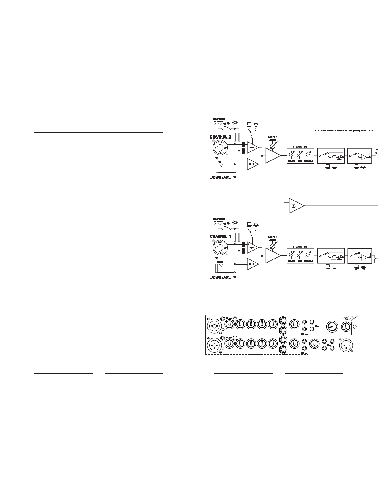
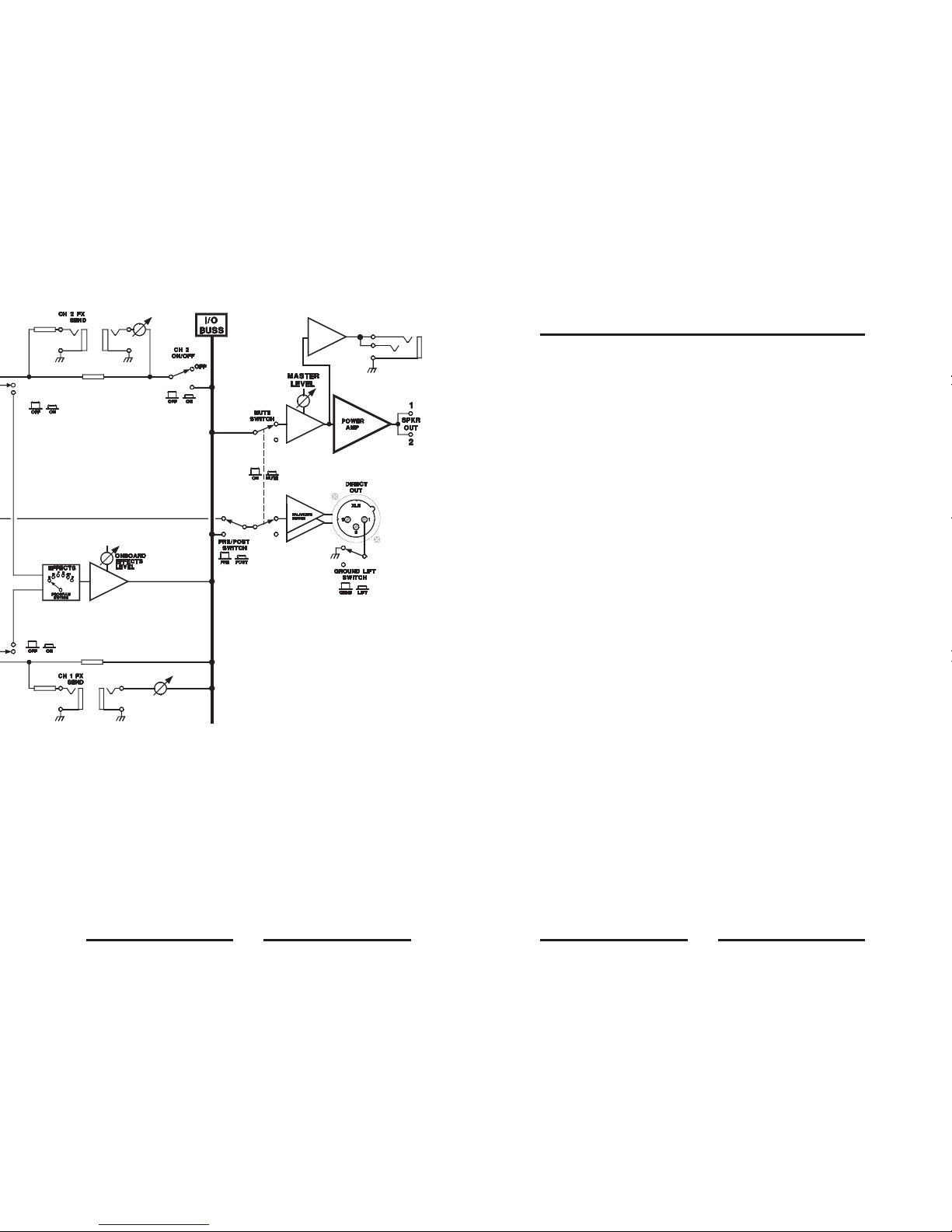
Signal Flow Diagram 5
Stereo Operation 7
7
Headphone Output 7
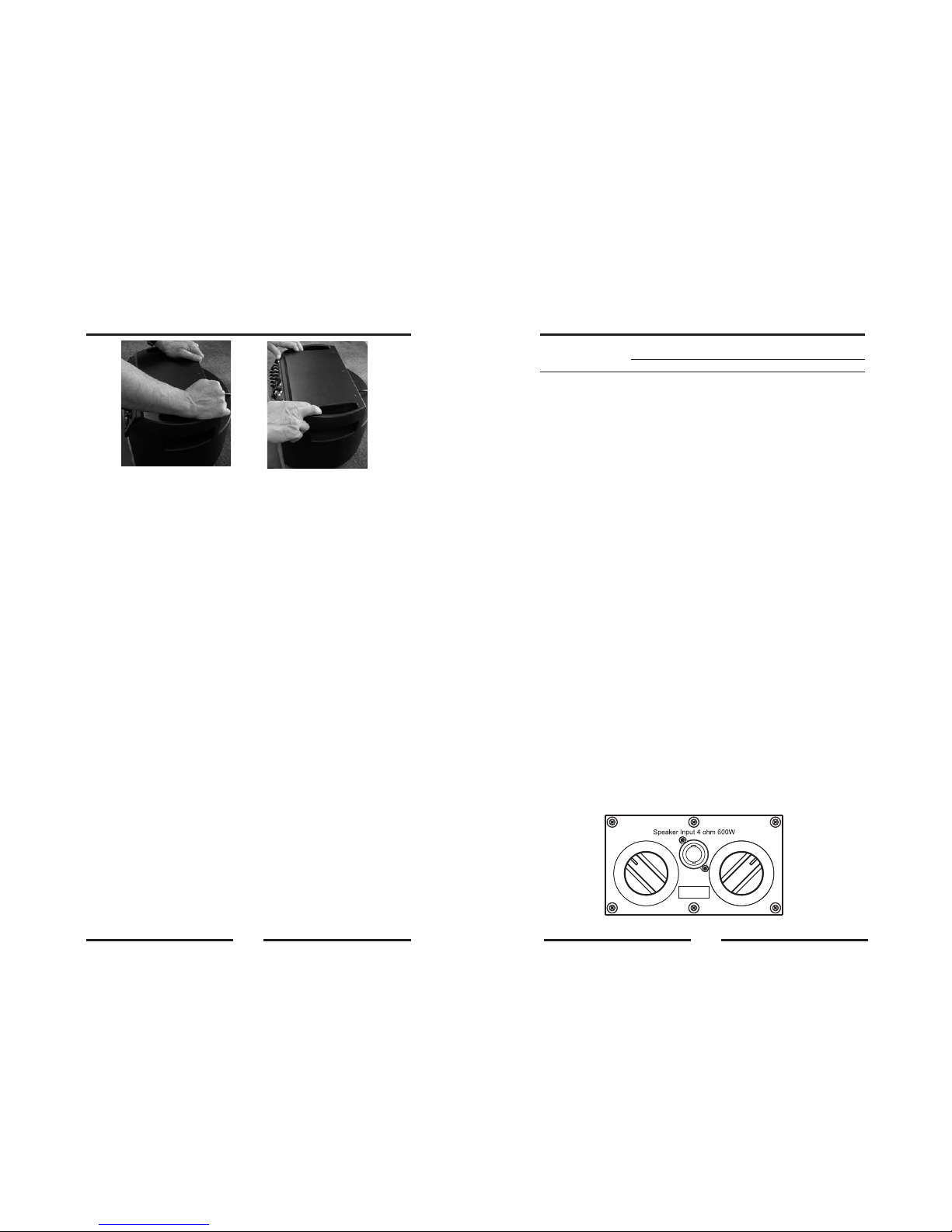
Docking System 7
Connecting An Ext Speaker 8
Speaker Placement 9
Tilt Mechanism 9
Tweeter Level Control 9
Room Coupling Control 10
Description of the Ten2 EX 10
Care 10
Warranty And Repair 10
Specifications 11
Low Cut Filter/Phase Reverse 3
Effects Loop 4
Direct Out 4
Mute Switch 4
Effects
Contents
The information in this manual is subject to change without notice. No part of this manual may be
reproduced by mechanical, electronic or other means in any form without prior written permission from
Acoustic Image.
The Acoustic Image logo is a registered trademark ofAcoustic Image LLC. Contra, Coda+, Corus+, Ten2,
Ten2 Ex, Room Coupling Control and Cabrio Docking System are trademarks of Acoustic Image LLC.
1
Welcome to Acoustic Image!
You have purchased a state-of-the-art musical instrument amplifier system,
combining purity, power and portability in a package that sets a new standard
in high fidelity amplification.
Each of our designs is engineered to accurately reproduce the sound of
acoustic and electric instruments, delivering flat frequency response across
the entire musical spectrum; extended, tight, well-controlled bass; and
complete clarity of sound reproduction.
This manual provides operating information for your Acoustic Image Ten2 and
the Ten2 EX extension speaker cabinet.
The Basics
The Ten2 has a superb class-D power amplifier with switch mode power
supply, a compact two-way speaker system and a sophisticated, sensitive
preamplifier. It also has the exclusive Cabrio Docking System that allow the
head unit to be removed and used as a stand-alone amplifier.
The power amp is a high efficiency, 800W design that requires no external heat
sinks or cooling fans and is capable of driving loads as low as 2 ohms. AC
power and output speaker jacks are located on the rear of the enclosure. A
standard, three-prong detachable AC power cord is used to provide power to
the unit, while an AC voltage selection switch allows the unit to operate at
115V/60 Hz or 230V/50 Hz. Japan models operate at 100V, 50/60 Hz only. See
the rear panel of your amp to verify theAC voltage capability.
The input channels of the preamp incorporate combo jack interfaces that allow
either a high impedance instrument input (to optimize the sound of piezo-type
pickups) or a mic input with a built in 10 dB pad, an effects
loop with return level control, a selectable low cut filter for reduction of low
frequency boominess, a phase reverse switch, a direct out capability with
ground lift and pre/post EQ switch, a master level control and a mute switch.
The preamp also has a switch that allows the second channel to be
disconnected from the main amp and connected to a satellite power amp to
create a stereo system.
The speaker enclosure incorporates a 2x10-inch woofer configuration (one is
downfiring and the other is front firing) and a 2.5-inch tweeter that is coaxially
mounted in front of the front firing woofer. The tweeter has a three position level
control (0 dB, -6 dB and off). The exclusive Room Coupling Control allows the
user to adjust the output of the downfiring woofer to help control boominess in
certain acoustic settings. A built-in, spring-loaded tilt mechanism allows the
cabinet to be tilted back to better direct sound to your listening position. The
cabinet is made of an acoustically inert, high durability, injection molded
polymer material which dramatically reduces the weight of the cabinet. Each
unit comes with a fitted slip cover and shoulder strap. A padded case is
available.
a three-band EQ,
The Ten2 is the loudest combo amp that we make but in designing it, we chose
fidelity over efficiency so it won’t play as loudly as the typical, lower fidelity 2x10
system. To generate higher SPLs may require an extension cabinet like the
Ten2 EX or augmentation by a larger house system.